This is the week where we are creating something BIG, and big to Neil is life size big.
NOTE:
This following part of the documentation took part before the Covid-19 shutdown in the UAE. The documentation was half done, the design was ready, and I am a strong believer in the statement that no effort is ever wasted, so I am keeping this part of the documentation XD.
This week, I was equally excited and fearful for the work. The thought of creating something big was thrilling, the thought of designing it however was not as exciting to me.
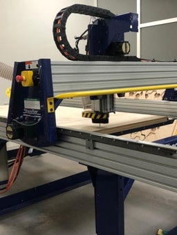
Our very first introduction to the marvelous ShopBot CNC machine was during the winter camp, where we briefly learned about the machine. Last week, we were re-introduced to the machine, and learned how to operate it and how take exceptional safety precautions around this particular machine.
Admittedly, designing is the most challenging part of this process for me. I went through numerous posts on Pinterest, Instagram and Fab academy documentations to find inspirations for the design I wanted to create.
And so with the time running and me not getting anywhere, I decided to start looking for tutorials and start designing, and perhaps if I am lucky enough the design would present itself to me!
I started by watching the laptop stand tutorial to understand more about creating parametric designs and joints in fusion, all the way to MDF box design tutorial for parametric finger joints, and flat pack furniture tutorial.
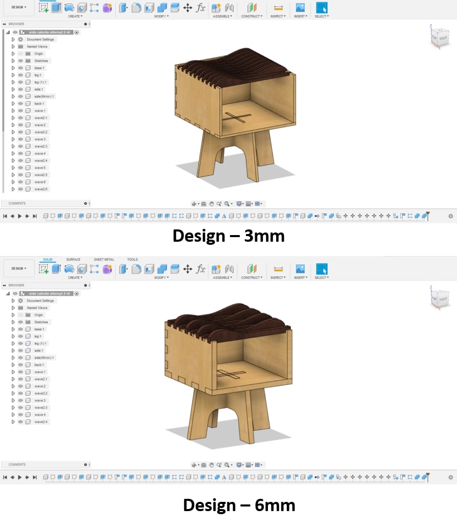
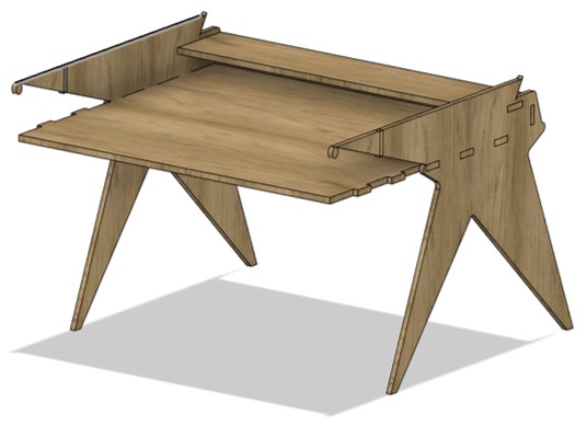
While doing so, I decided to create a table with an open drawer. The design consists of 3 main parts, the legs, the “box” or drawer itself, and the curved top.
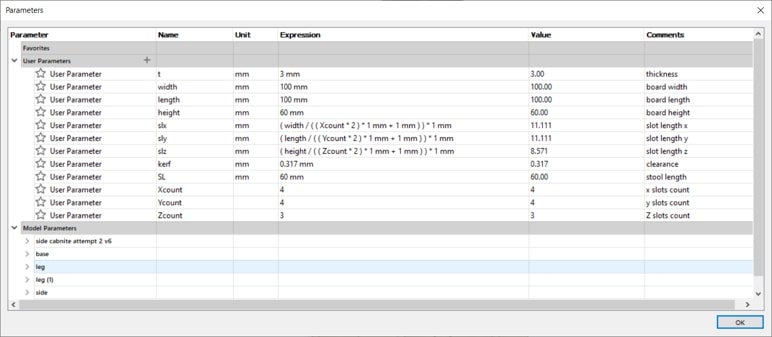
I wanted to try making the whole design as parametric as possible.
I took a top-down approach for designing the legs, starting by the base of the drawer and working down to the legs. As for the rest of the drawer, I used bottom-up approach, to create the sides and the top curved part.
and the final design looked something like this:
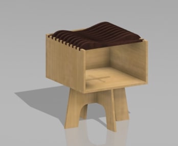
After the rendering process:
Before the cutting the design on the Shopbot, it is required to use the laser cutter to properly check the design for any mistakes before the actual milling.
The process of milling and assembly is halted temporarily due to the Covid-19 shutdown. I will try completing these steps as soon as access to the lab is granted again! _____
Following our return to the lab safely, I decided to change the design I was working on for something that might be easier to accomplish given the limited time we have, and the practicality of the design I had in mind previously.
So here we go again!
Thankfully, the research and the tutorials I watched previously, along with attempting the previous model helped significantly in clearing some design hindrance for me.
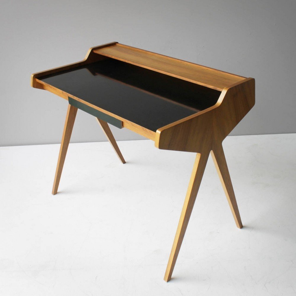
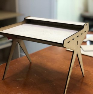
This time I attempted to create a writing desk designed by Helmut Magg in the early 50’s. I followed this tutorial to design the desk on fusion 360 with some tweaks that I found necessary for my model.
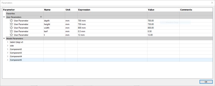
I attempted to make the design as parametric as possible by assigning values to different parameters (spoiler alert: it didn’t work as expected). I found designing the model in its real life size and then scaling it down (for testing) is much more efficient than going on the opposite approach.
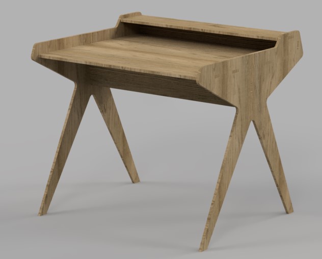
and after the rendering:
As mentioned previously, prior to using the Shopbot, we need to test the design by cutting a smaller model of it using the laser cutter. Since the design was supposedly parametric, I decided to simply attempt changing the values I had set for the parameters to scale down the model. That unfortunately did not work, as the design got all distorted as the sketch of the desk side was a bit too complex.
This issue was simply solved by scaling the model in fusion 360 using the ratio I needed.
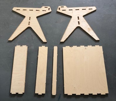
I projected the sketch of each part of the model (there were 6 parts in total), and took the DXF files of it. Then I opened the DXF files in Coral draw, and laser cut the test model on a 3mm MDF sheet.
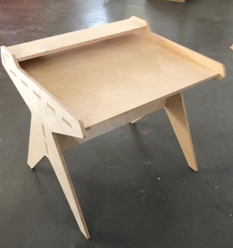
After assembling:
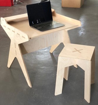
It is evident that the model has some stability issues, it is stable enough to hold some slight weight (my phone is an example here), but if pushed it would sway from side to side.
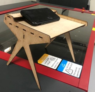
Thus I increased the width of the support piece in the middle to provide more stability to the design. Nonetheless, I like how the desk turned out!
Now comes the tricky part.
Ahead of working with the CNC Shopbot, precautionary measures had to be taken. We were informed of the “Safe places” to stand while the machine was in operation, which in our case were near the outer right corner of the machine, or behind the glass door of the room.
Also, personal protection equipment had to be worn when working with a CNC machine this big and powerful. Lab coats, protective goggles, ear plugs and gloves were the basics.
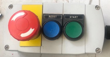
Furthermore, we were made aware of the emergency buttons on machine and on the controller just in case something goes wrong.
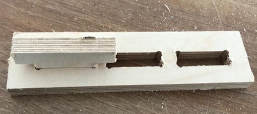
Similarly to working with the laser cutters, we needed to measure the clearance the machine. To do so, I created a simple design with slots that varied 0.2 mm in width to see which would fit the best.
![]()
I milled the pieces (the process is described further below) and tested for the clearance value which came to be sheet width + 0.2 mm
I added that clearance to the slots in the design and took the DXF files of the parts.
First we need to generate the toolpaths in g-code so the CNC can understand the coordinates. I used Vcarve which is a software solution for creating and cutting parts on a CNC Router.
Thankfully, the sheet we were using had been previously secured to the CNC bed by drilling and placing screws around the parameters of the sheet. And the screw placement was already marked in Vcarve working space. I imported the DXF files as vectors, and placed them in such a way that the milling path will be far from the screws avoiding any potential hazards.
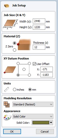
Next, I clicked on set job dimensions and origins under job operations, and set the material thickness to be 12mm.
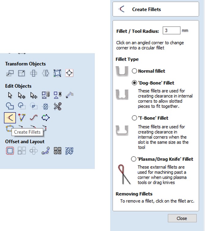
Then, I clicked on create fillets under edit objects, and chose dog bone fillets. These fillets are used to create clearance for internal corners to allow slotted pieces to fit together. I added the fillets to the corners of all the slots, as well as the corners of taps that would fit into the slots.
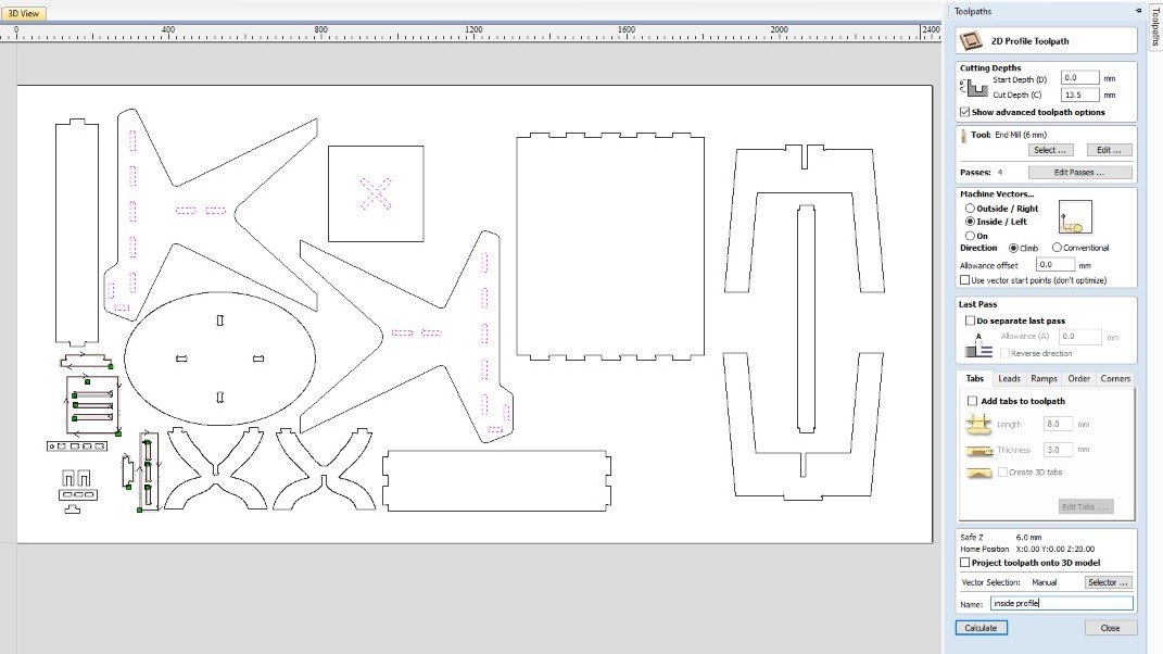
Next, I clicked on the toolpaths tab on the upper left, and selected the Profile toolpath. This is to cut the inner parts of the design, slots for example, first. And entered the following settings:
In cutting depths set the cut depth to 13.5 mm to ensure that the pieces are cut all the way through.
In tool select the 6mm End Mill, set the spindle speed to 14000, the feed rate to 60, plunge rate to 10 and edit the number of passes to 5 passes. Increasing the number of passes allows the end mill to go down a certain depth at a time, if not the high load on the tool may damage the end mill.
In machine vectors select inside/left, and select climb for the direction.
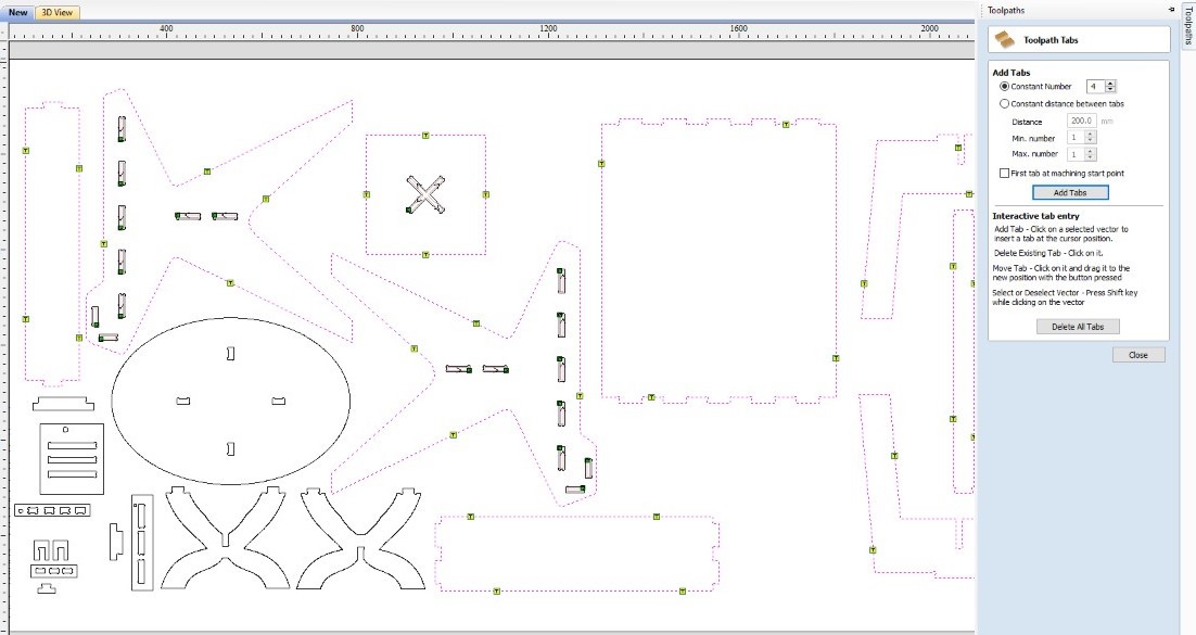
Check the add tabs box at the end, and set the tab length to 8mm and the tab thickness to 3mm. Adding tabs will prevent the pieces from moving or flying away while milling.
Lastly, click on calculate to generate the toolpath.

Next is the outside profile, which has the exact same settings as the previous toolpath except for:
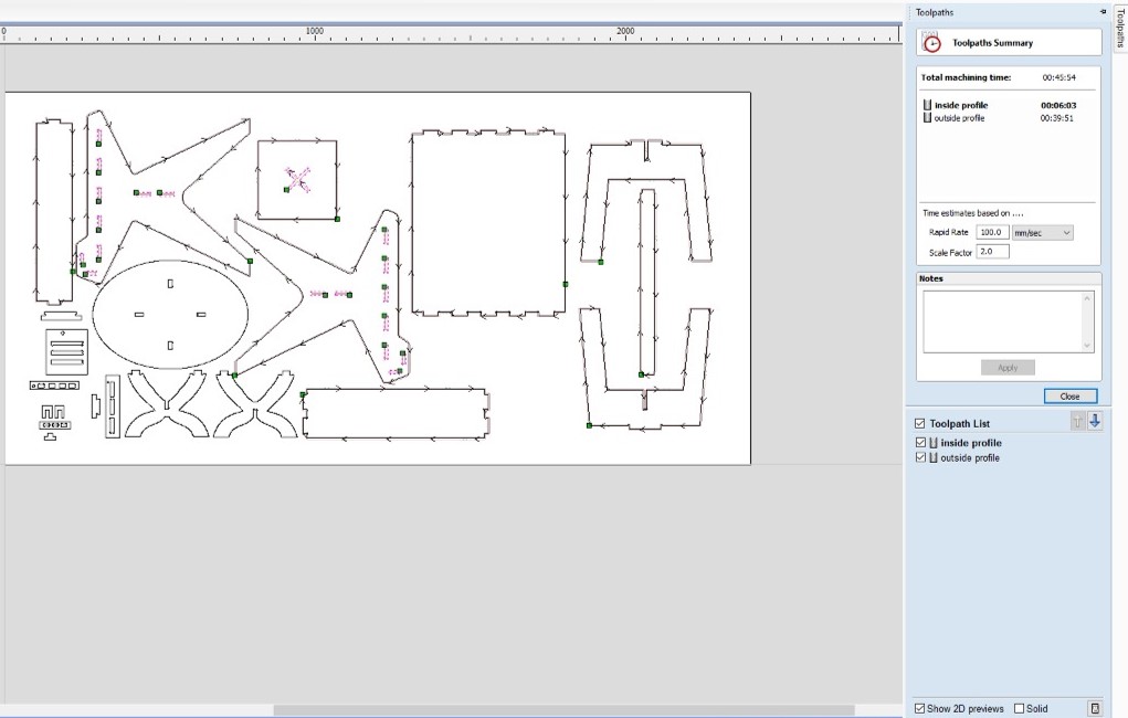
outside/left in the machine vectors section.Once the tool paths are ready, we can hover over them or select summery of all toolpaths to display the estimated time for milling. Then just save the toolpaths!
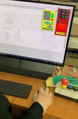
To start working, the origin points for the milling have to be set. This is done by accessing the Shopbot Control Software, and calibrate the XYZ values using the position keypad. To calibrate the XY positions, we shift the machine using the arrows on the keypad or using the keyboard, to position required, then click on zero axes and tick the x and y zero boxes.
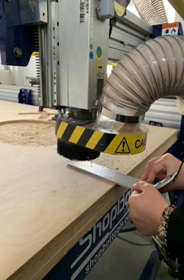
As for adjusting the height or the Z value, the process is a bit different. First, we click on the zero z button on the keypad, and follow the instructions requiring the clip to be attached to any metal part of the machine, and the metal bar to placed on the surface of the piece we are milling.
We can test the metal bar for conductivity if we make it touch the milling bit and input 1 flashes in the control keypad.
Once the Z-Zero command is running, the milling bit goes down to touch the metal bar on the surface twice to confirm the height of the sheet.
and we’re done with the settings :)
Finally, we can click on cut part button on the keypad to select the g-code toolpath file, follow the procedure and click on the START button on the controller!
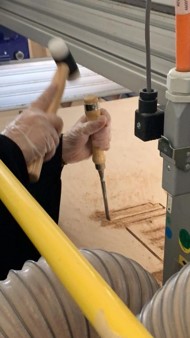
Thankfully, the milling process went smoothly, and it was now the time to remove the pieces and assemble!
Unfortunately, the ventilation of the Shopbot was not working that day so we had to remove the wood shavings manually. This was easy to do, however, it made breaking the tabs a tad harder to do since we couldn’t see them properly.

Next, we took out the pieces and started sanding it using metal files and sanding paper.
Finally we can start assembling , which honestly was the hardest part to get done considering the slots alignment, and the number of pieces my design had. But with a little bit of luck, and a lot of girl power (featuring Shaikha and Fatima) we managed to get this desk assembled.
The desk turned out great! it is sturdy and cute looking and it paired nicely with Shaikha’s work for this week!
I was a bit worried regarding this week before it really came. I had different concerns in mind in regards to the designing process, and operating the machine itself. These concerns faded out by the end of this week, and I can confidently say that the computer controlled machining week was one of the most fun experiences I had in fab Academy. Also, it made me explore more in CAD designing, to a point where I even find it enjoyable now!
Please find the group assignment here.
