Week 17: Mechanical Design, Machine Design
Google drive with all filesGroup Assignment
Discussion phase
Although we had many ideas for what machine we can build for this week, we decided to do something that we will actually use in Lab and what we really need. Our choise was 3-Axis hot wire machine. We already have some expiriance in DIY machine building, 3D printers mainly, anwyway we decided to look thought the internet.
After few hours of looking and searching we discussed pros and cons of many designs and solutions. Like general construction, microcontroller, power supply and motion principle.
Discussion made us choose a build that will be based on gate build of the 3D printer since it is contains common parts and we already know it works well it that kind of mechanisms. The machine will be runned on Arduino with RAMPS and NEMA 17 stepper motors.
Designing phase
For desining we chose the Fusion 360 software since we both know it and we can share the design and work on it together. As 1st we gathered all parts that we might use.After a while of design thinking we started to get something machine looking like :)
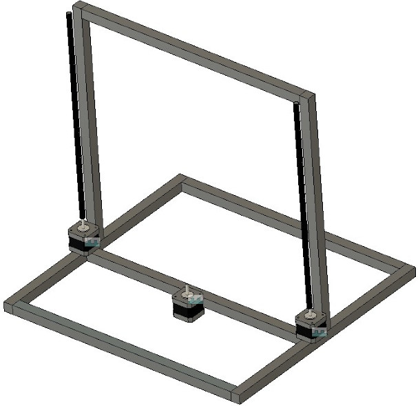
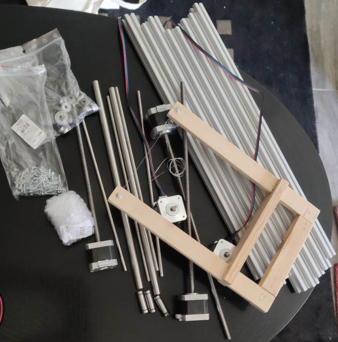
After we got main , not too detailed design of the machine we started to gather the parts.
Unfortunately due to high traffic in speditions and the fact that we are working from two different cities right now, made our progress on the machine got a bit delayed.
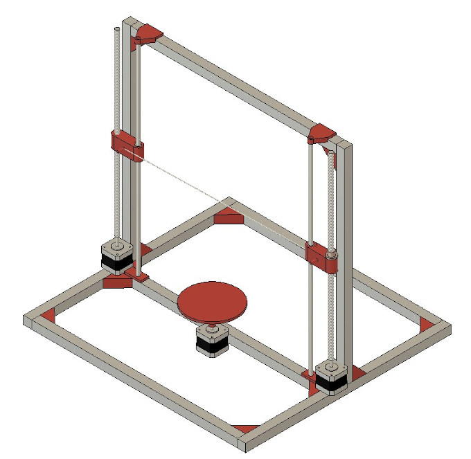
Our design looks as following, all is left is to gather all parts, print all STLS and assamble :)
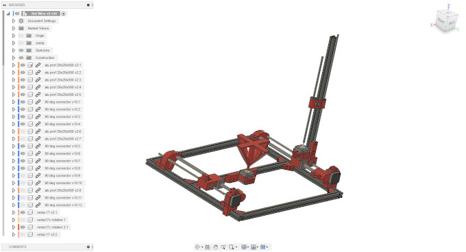
After few iterations the final design looked as following (one side and top bar hidden for better presentation):
Now when the design is made by Maciek and parts are at Piotr's place it is time to start priting the rest and assembling.
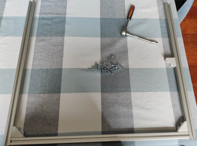
Assembling phase
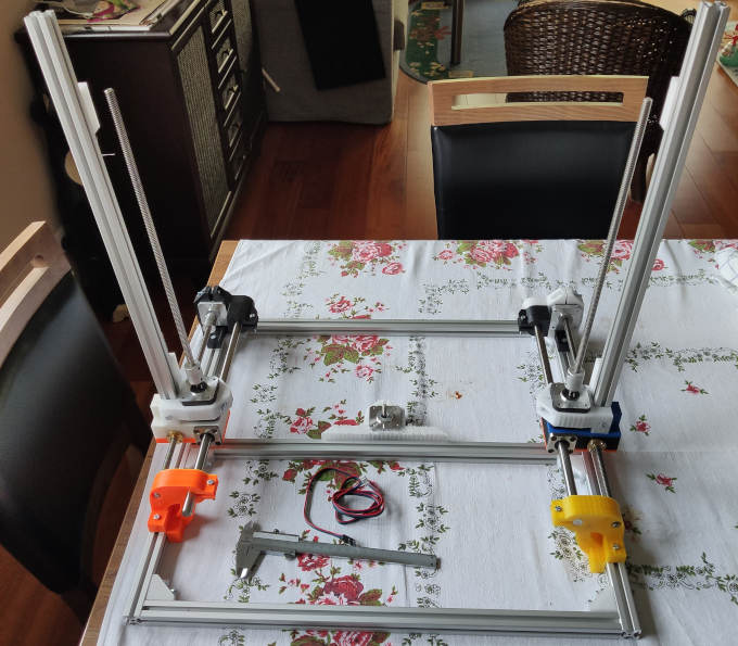
1st goes the base of the frame.
Of course I had a great help :)
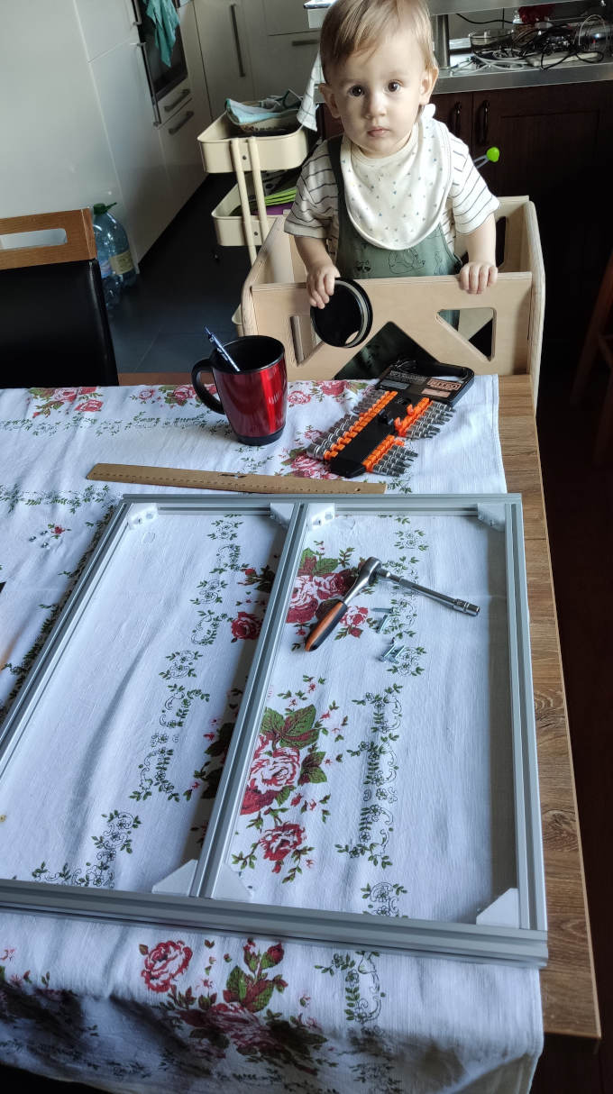
Then linear rods and rails with motors.
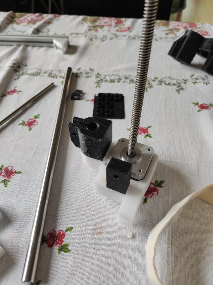
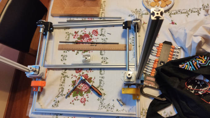
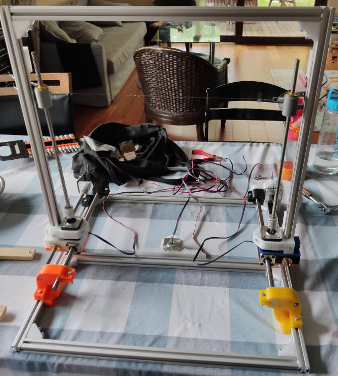
Then the top beam goes in and Z-Axis carriges with hot wire.
Now it is time to add electronics. For this project we will use Arduino UNO with CNC Shield attached.
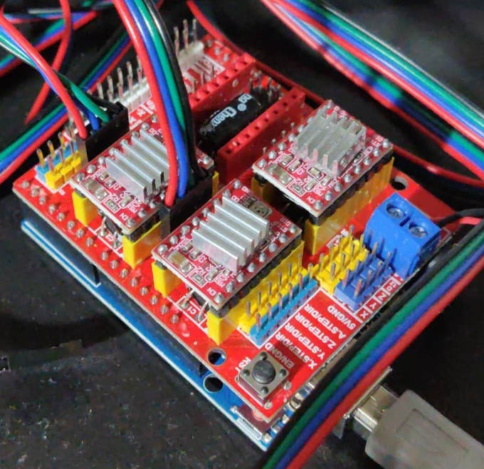
It will use 12V power supply typically used in this kind of projects.
After everything is conencted and assambled, it is time to load the firmware into the board and test if everything is working.
Software
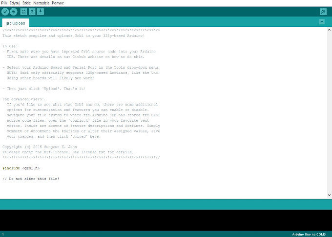
The firmare I will use is the standard Grbl firmware. It can be downloade On this github page .
To load the firmware I will use Arduino IDE.
To control the board I will use the Universal Gcode Sender.
It is a free software that simply send GCode to any standard machine.
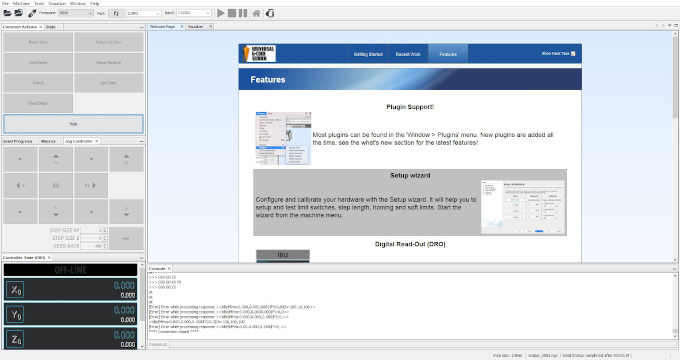
After sucesfully connecting to the machine I can run a setup wizard in which I can configure the entire machine.
The most crucial part is calibration.
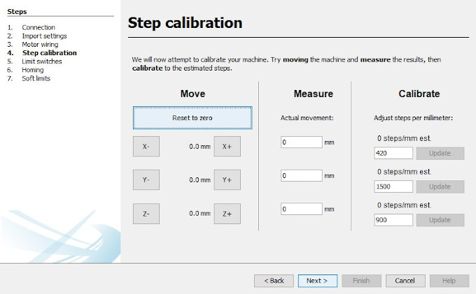
At this point I define the steps that the stepper motor makes for each real life mm of travel.
After the calibration and configuration is complete I can generate some gcode to test if machine works properly.
GCode making
To make the gcode I will use Inkscape. This software containt a plug-in tool that converts the path into gcode.
1st of all I need to set-up the workspace to match my work space. To do it I have to go to File > Document Properties and there Size setting. Set it in mm to be as my work space.
Then I can upload any graphic file. I will use FabLab logo.
After uploading the graphics I use "Trace Bitmap function" to convert the bitmap into trace.
Now I can setup the orientation point and tool for Gcode generation feature.
For orientation point I go to Extenions > Gcodetools > Orientation Points and simply press OK.
Now for the tool: Extenions > Gcodetools > Tools Library and there I have to select Cylinder .
A green window will pop up on the work area.
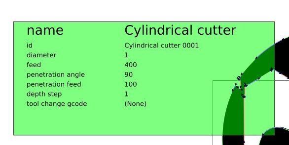
On of the things that have to bo changed is the "Diameter", in standard setting it will have a value of 10. We have to change it into 1 as we have very thin wire as a tool.
The last thing in Inkscape is to use Extenions > Gcodetools > Path to Gcode... feature.
After using it we will have a .ncg file that we can use in Universal Gcode Sender.
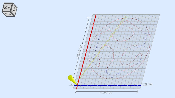
Now I can run the gcode and see how the machine works, without the foam first.
After confirming that the machine works properly I can connect the wire into the main cutting wire to make it hot and run a cutting with foam this time:
And this is a cutting result:
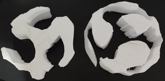
It is visible that the wire needed tensioning. Unfortunately it snaped after fixing the tensions so there was no next change to make better cut.(as visible on video)