Week 14: Networking and Communications
Invidal Assigment:
design, build, and connect wired or wireless node(s) with network or bus addresses
Group Assigment:
send a message between two projects
Google drive with all files
Making of the PCB's
Ow boy... what a week. We have to make two boards and also make them communicate! Gonna be fun!I decided to make something very simple. A board with the button and it will light a LED on the second board.
So lets start with Eagle!
Design of boards
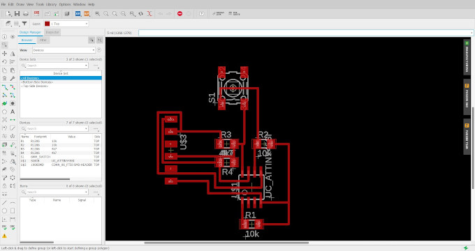
A Master board with button based on ATtiny45: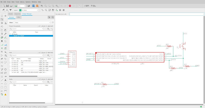
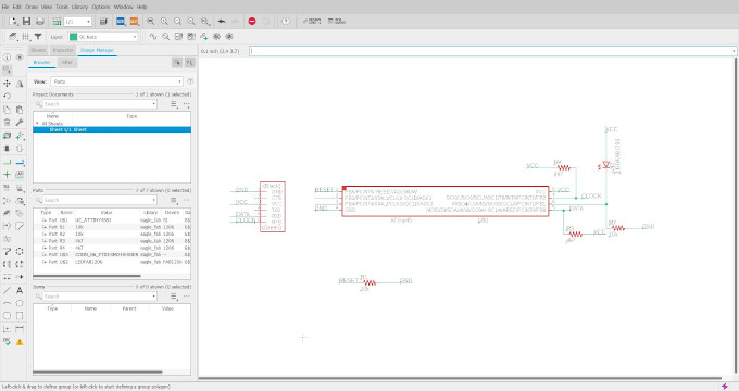
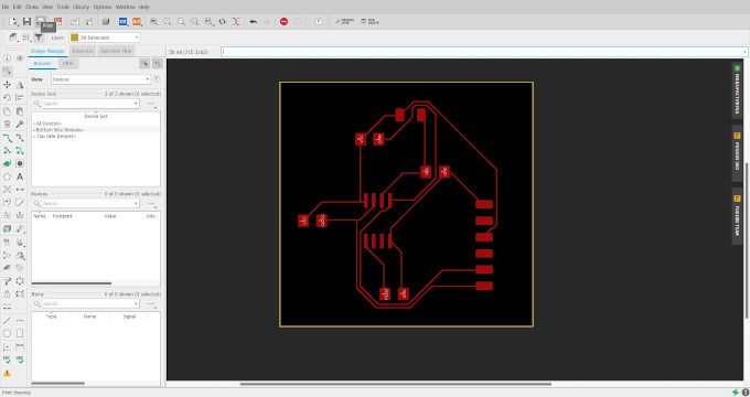
And slave board:
Making of the boards
Since I do not have an access to my lab , due to Covid lockdown, I will try to use a product from my company that I work at.It is a ZMorph VX multi-tool machine.
I will use a FR4 board and gain a board by chemical etching and laser engraving. More of the process in following instruction!:
1st step is to paint the PCB boards with the black paint.
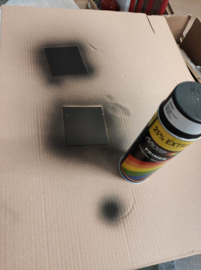
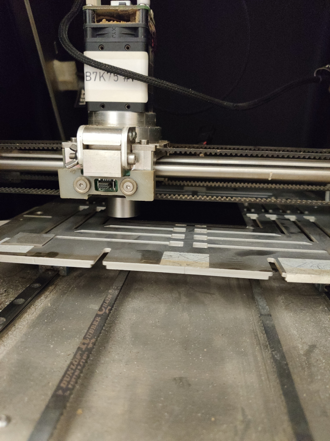
And place them on the machine.
Now lets make a gcode in dedicated software for the machine which is the Voxelizer.
But 1st I use verctorization module on mods to change the BMP output file from eagle into SVG, I will use those SVG files in Voxelizer.
OK now I import the files into the voxelizer:
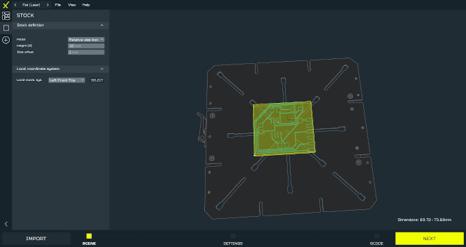
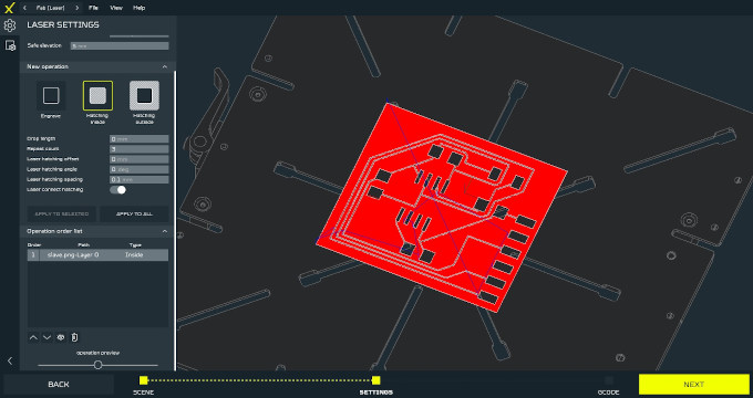
After importing the file I need to set the settings for laser engraving. The laser will evaporate the paint leaving the paint of traces.
Settings for laser:
And the gcode looks as following:
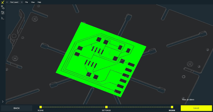
With the gcode ready I can load everyting on the machine.
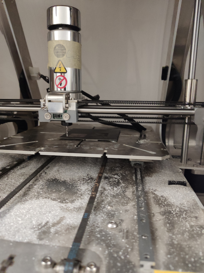
1st I use the double sided foam tape to fix the prepared laminated board on the machine's steel work table.
Lets charge up the lasers!!!
After laser engraving:
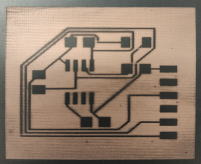
There are some cutted traces but I can correct them with black hightlither for PCB's.
Now cutting out of the boards:
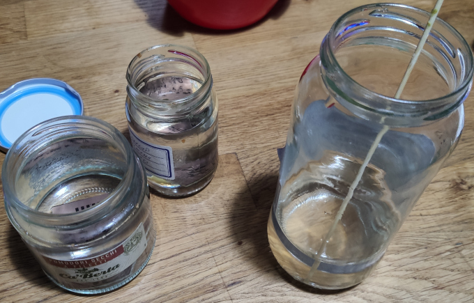
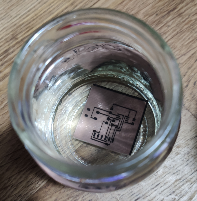
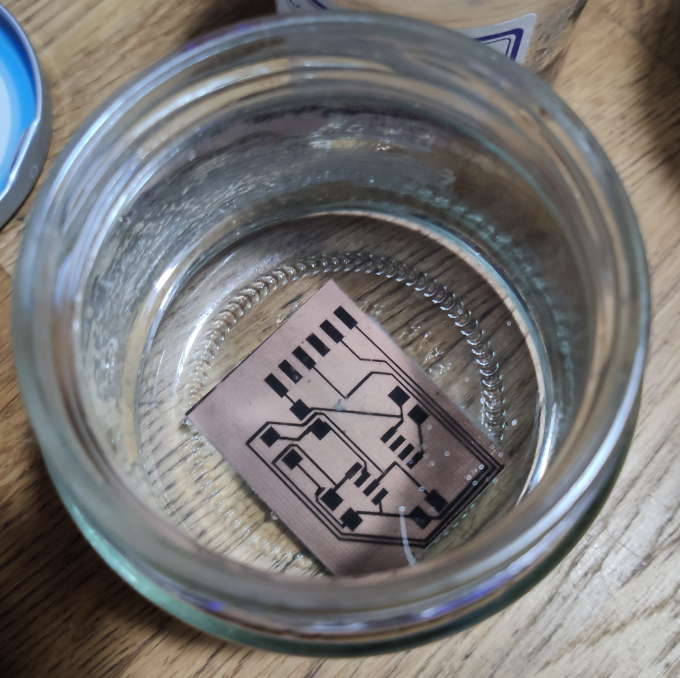
Now last step is to etch the board in the acid (sodium persulphate). I mixed the crystalised sodium persulphate with warm water (max 50C deg) in one jar. Putted the ready PCBs in two separate jars and poured the mixture into them.
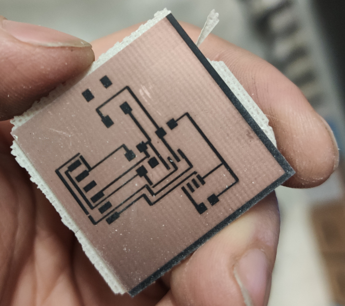
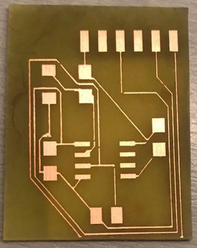
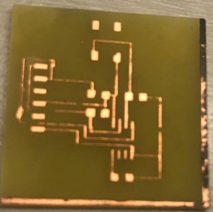
Now after eaching I have to clean the boards from the paint leftovers.
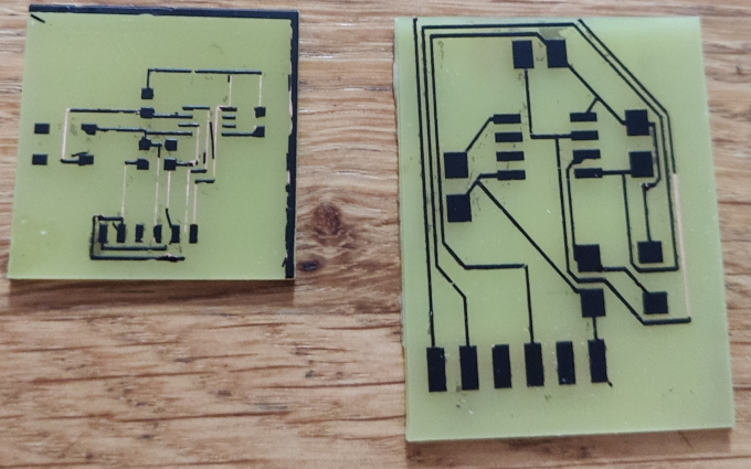
I cleaned the board with the alcohol... aaaaaaaaaaaaaaaand I failed... I left the boards for too long in the acid and some of the traces got eached too much :(
I will try once more as soon as I get new laminates, unfortunately due to covid stationary stores are close :(
Arduino Version
Since I am not able to finish my task on self made PCB's I will make something simillar on Arduino UNO boards. But 1st I will make a simulation on Tinercad Cirtucs web app.For communication I will use Wire protocol that bases on I2C communication. As always 1st I read the official manual on Arduino web page:
https://www.arduino.cc/en/Reference/Wire
Circuit
Lets build a circut!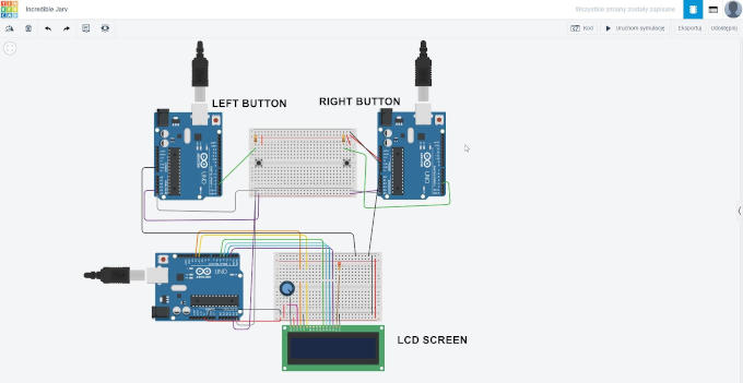
I connected three Arduino Uno boards via wires on I2C (A4 and A5 pins). Two Arduinos have buttons, left and right button. Pressing the button on each side will send a message to the master arduino with LCD screen. The LCD screen will inform which button was pressed.
The code
Each board need a code to work. There are to slave boards and one master board. The boards will send the sinal and master will recieve it. The master board will write on the LCD screen which button was pressed.
Code for the master board:
#include LiquidCrystal.h
#include Wire.h

LiquidCrystal lcd(12, 11, 5, 4, 3, 2);

void setup() {
  Wire.begin(1);
  Wire.onReceive(receiveEvent);
  Serial.begin(9600);
  lcd.begin(16, 2);
  lcd.print("You  pressed:");
}

void loop() {
  delay(250);
}

void receiveEvent(int howMany)
{
  while (Wire.available())
  {
    char button = Wire.read();
    Serial.println(button);
    if (button == 'l')
    {
    lcd.setCursor(0, 1);
  	lcd.print("Left button");

    }
    else if (button == 'r')
    {
     lcd.setCursor(0, 1);
  	 lcd.print("Right button");
	}
  }
}
Code for slave left and right:
	#include
const int buttonPin = 3;
void setup()
{
Wire.begin();
pinMode(buttonPin, INPUT);
Serial.begin(9600);
}
void loop()
{
if (digitalRead(buttonPin) == HIGH)
{
Serial.println("BUTTON RIGHT HIGH");
Wire.beginTransmission(1);
  Wire.write("r");
  Wire.endTransmission();
  delay(500);
}
}
The code for the left Arduino is simillar with the change that it sends "l" to the master board.
Simulation works as shown on following video:
Time to build real circut.
Assembly time!
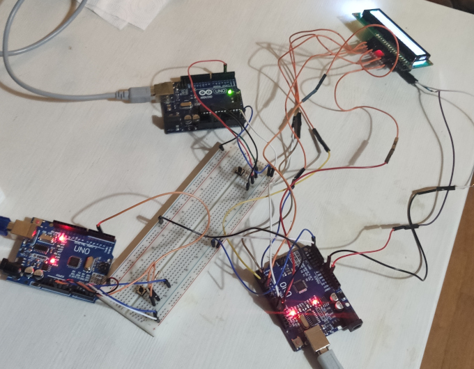
Unfortunately due to wrongly connected wires I have burned the LCD screen and it is not communicating with the boards :(
The serial communication indicates that the communication between the boards works:
I changed the LCD screen into a simpler and more basic version, two LED's:
Group Assigment
The group assigment was supposed to be a merge of two previous project with added one more board that will communicate those two boards. I will use Arduino boards for this one as well. I will make a simulation in Tinkercad as 1st.Tinkercad Simulation
The project will have three Arduino UNO boards:- 1st one as a slave, with photoresistor to measure the level of brightness "outside"
- 2nd one as a master and slave at the same time. It will take a level of brightness from the 1st board and process/show it on the LCD screen. If the level of brightness is above some value it will send a signal to the 3rd board.
- 3rd one as a master. This board will have servo motor that will move to certain position whenever the level of brightness is above some level
Circut
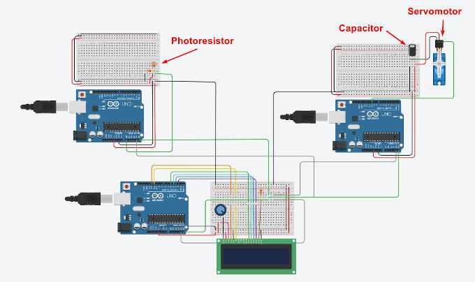
Code for the 1st board with photoresistor:
int lightlevel;
#include (Wire.h)

void setup()
{
  Wire.begin(2);
  Wire.onRequest(requestEvent);
  Serial.begin(9600);

}

void loop()
{
lightlevel = analogRead(A0);
  Serial.print("Level of light: ");
  Serial.println(lightlevel);
  delay(1000);
}
void requestEvent() {
  Wire.write(lightlevel);
}
Code for the 2nd board with LCD Screen:
	#include (LiquidCrystal.h)
	#include (Wire.h)
	LiquidCrystal lcd(12, 11, 5, 4, 3, 2);
	int c;
	int servo;

	void setup() {
	  Wire.begin(1);
	  Wire.onRequest(requestEvent);
	  lcd.begin(16, 2);
	  Serial.begin(9600);
	}

	void loop() {
	  lcd.print("Light level: ");
	  lcd.setCursor(13, 0);
	  Wire.requestFrom(2, 1);
	  while (Wire.available()) {
	    c = Wire.read();
	    Serial.println(c);
	  }
	  lcd.print(c);
	  if(c <= 100)
	  {
	      lcd.setCursor(0, 1);
	    lcd.print("It's still dark");
	    servo = 0;

	  }
	  else
	    {
	      lcd.setCursor(0, 1);
	    lcd.print("It's sunny");
	    servo = 1;
	  }
	  delay(1000);
	  lcd.clear();
	  Serial.println(servo);
	}
	void requestEvent() {
	  Wire.write(servo);
	}
Code for the 3rd Arduino board with Servo:
#include (Wire.h)
#include (Servo.h)
Servo servo_10;

int servo;

void setup() {
  servo_10.attach(10, 500, 2500);
  Wire.begin(1);
  Serial.begin(9600);
}

void loop()
{
  Wire.requestFrom(1, 1);
  while (Wire.available()) {
    servo = Wire.read();
    Serial.println(servo);
    if(servo == 0)
      servo_10.write(0);
    else if(servo == 1)
      servo_10.write(90);
  }
  delay(1000);
}
So basically the 1st Arduino board works as an input and reads the level of light in the room and sends it into the 2nd board which is the processing board, if the level of light is high enough then the board sends the signal into the 3rd, output board, with servo that moves. Move of the servo indicates movement of motor that would open or close the blinds in the room for example.
Video of the simulation:
Real-life Simulation
So now when I have tested the circut in Tinkercad I can create the real-life one.
So...
Assamble time!
Real circut test:
Go back to front page Go back to Week 13 Go to Week 15