Week 08: Embedded Programming
Individual assignment:
* read a microcontroller data sheet
* program your board to do something with as many different programming languages and programming environments as possible
Group assignment:
* compare the performance and development workflows for other architectures
Group Assignment
Our task for group in this week was to test the performance and developement workflows for other architectures.Types of architectures
To make this assigment undestandable for all it is the best to 1st show what kind of different architectures we can use in this assigment and most importantly what is the architecture of microcontroller.What is microcontroller?
"A microcontroller is essentially a small computer on a chip. Like any computer, it has memory, and can be programmed to do calculations, receive input, and generate output. Unlike a PC, it incorporates memory, a CPU, peripherals and I/O interfaces into a single chip. Microcontrollers are ubiquitous, found in almost every electronic device from ovens to iPods."[1]
What is an architecture of microcontroller?
Architecture is a set of attributes of the microcontroller visible by the developer. Those attributes have impact on the logical execution of commands. Example attributes are orders list, in and out operations or methods of addressing the memory.
Types of architectures
We can distinguish two most common types:
- Harvard - AVR Microcontrollers for example used in Arduino boards
- Von-Neumann ARM Microcontrollers for example used in Raspberry Pi
Differences between two Harvad and Von-Neumann architectures
Von-Neumann Architecture Scheme[2]:
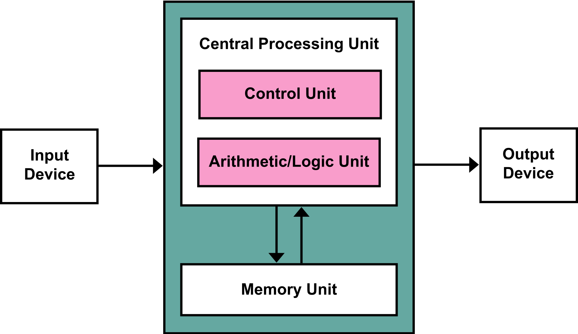
The Von Neumann architecture consists of a single, shared memory for programs and data, a single bus for memory access, an arithmetic unit, and a program control unit. The Von Neumann processor operates fetching and execution cycles seriously.
Harvard Architecture Scheme[3]:

The Harvard architecture has two separate memory spaces dedicated to program code and to data, respectively, two corresponding address buses, and two data buses for accessing two memory spaces. The Harvard processor offers fetching and executions in parallel.
Test
AVR Microcontrollers on Arduino UNOI programed my board and tested on an Arduino in virtual enviroment in Tinkercad Cirtucts on www.tinercad.com. Since I have already a board made there I decided to reuse it. I will make the old board use the LED supplied already plus additional one and say "HELLO WORLD" in Morse code after pushing the button. So one LED on will be a short signal and two LEDs on will be a long signal.
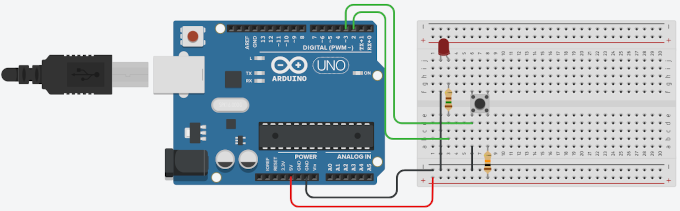
So 1st thing that I have to do is to add new LED to the current setup.

The new LED is connected with the board via turquoise wire and thats make the board complete and ready to get programed.
All is left is to write the code... and yeah, learn Morse Code!!!
So lets 1st look at the Morse Code Graph[1].

I will use this graph as a reference for making the code.
So lets dig into code! The code we will use C language.
I will start from reusing the previous code so I will simply add the new LED as an output on PIN number 4 (turquoise wire).
const int buttonPin = 3; //Pin for the button
	const int LEDPin = 2; //Pin for the LED
	const int LEDPin2 = 4; //Pin for the LED2 (added line)

	void setup()
	{
		pinMode(buttonPin, INPUT); //setting the input PIN
		pinMode(LEDPin, OUTPUT); //setting the output PIN
		pinMode(LEDPin2, OUTPUT); //(added line)
		Serial.begin(9600); // Serial console setup
	}
H is * * * *
E is *
L is * - * *
O is - - -
W is * - -
R is * - *
D is - * *
So the finally it should look like:
(H) * * * *
(E) *
(L) * - * *
(L) * - * *
(O) - - -
(W) * - -
(O) - - -
(R) * - *
(L) * - * *
(D) - * *
The LEDs will start to blink after pressing the button so there is also a check for the button state.
		if (digitalRead(buttonPin) == HIGH) //checking the state of the button
		{
So after the state of the button goes HIGH meaning that it was pressed and blinking code is executed.Full code looks as following:
		const int buttonPin = 3; //Pin for the button
	const int LEDPin = 2; //Pin for the LED
	const int LEDPin2 = 4; //Pin for the LED2

	void setup()
	{
		pinMode(buttonPin, INPUT); //setting the input PIN
		pinMode(LEDPin, OUTPUT); //setting the output PIN
		pinMode(LEDPin2, OUTPUT);
		Serial.begin(9600); // Serial console setup
	}

	void loop()
	{
		if (digitalRead(buttonPin) == HIGH) //checking the state of the button
		{
			Serial.println("Start H"); // H is 4 shorts
			digitalWrite(LEDPin, HIGH); //setting the LED on
			Serial.println("*");
			delay(500); //0.5s delay
			digitalWrite(LEDPin, LOW); //setting the LED off
			delay(500); //0.5s delay
			digitalWrite(LEDPin, HIGH); //setting the LED on
			Serial.println("*");
			delay(500); //0.5s delay
			digitalWrite(LEDPin, LOW); //setting the LED off
			delay(500); //0.5s delay
			digitalWrite(LEDPin, HIGH); //setting the LED on
			Serial.println("*");
			delay(500); //0.5s delay
			digitalWrite(LEDPin, LOW); //setting the LED off
			delay(500); //0.5s delay
			digitalWrite(LEDPin, HIGH); //setting the LED on
			Serial.println("*");
			delay(500); //0.5s delay
			digitalWrite(LEDPin, LOW); //setting the LED off
			Serial.println("Ends H");
			delay(500); //0.5s delay
			Serial.println("Start E"); //E is 1 short
			digitalWrite(LEDPin, HIGH); //setting the LED on
			Serial.println("*");
			delay(500); //0.5s delay
			digitalWrite(LEDPin, LOW); //setting the LED off
			Serial.println("Ends E");
			delay(500); //0.5s delay
		Serial.println("Start L"); //L is 1 short , 1 long, 2 short
			digitalWrite(LEDPin, HIGH); //setting the LED on
			Serial.println("*");
			delay(500); //0.5s delay
			digitalWrite(LEDPin, LOW); //setting the LED off
			delay(500); //0.5s delay
			digitalWrite(LEDPin, HIGH); //setting the LED on
			digitalWrite(LEDPin2, HIGH); //setting the LED2 on
			Serial.println("-");
			delay(500); //0.5s delay
			digitalWrite(LEDPin, LOW); //setting the LED off
			digitalWrite(LEDPin2, LOW); //setting the LED2 off
			delay(500); //0.5s delay
			digitalWrite(LEDPin, HIGH); //setting the LED on
			Serial.println("*");
			delay(500); //0.5s delay
			digitalWrite(LEDPin, LOW); //setting the LED off
			delay(500); //0.5s delay
			digitalWrite(LEDPin, HIGH); //setting the LED on
			Serial.println("*");
			delay(500); //0.5s delay
			digitalWrite(LEDPin, LOW); //setting the LED off
			delay(500); //0.5s delay
			Serial.println("Ends L");
			Serial.println("Start L"); //L is 1 short , 1 long, 2 short
			digitalWrite(LEDPin, HIGH); //setting the LED on
			Serial.println("*");
			delay(500); //0.5s delay
			digitalWrite(LEDPin, LOW); //setting the LED off
			delay(500); //0.5s delay
			digitalWrite(LEDPin, HIGH); //setting the LED on
			digitalWrite(LEDPin2, HIGH); //setting the LED2 on
			Serial.println("-");
			delay(500); //0.5s delay
			digitalWrite(LEDPin, LOW); //setting the LED off
			digitalWrite(LEDPin2, LOW); //setting the LED2 off
			delay(500); //0.5s delay
			digitalWrite(LEDPin, HIGH); //setting the LED on
			Serial.println("*");
			delay(500); //0.5s delay
			digitalWrite(LEDPin, LOW); //setting the LED off
			delay(500); //0.5s delay
			digitalWrite(LEDPin, HIGH); //setting the LED on
			Serial.println("*");
			delay(500); //0.5s delay
			digitalWrite(LEDPin, LOW); //setting the LED off
			delay(500); //0.5s delay
			Serial.println("Ends L");
			Serial.println("Starts O"); //O is 3 long
			digitalWrite(LEDPin, HIGH); //setting the LED on
			digitalWrite(LEDPin2, HIGH); //setting the LED2 on
			Serial.println("-");
			delay(500); //0.5s delay
			digitalWrite(LEDPin, LOW); //setting the LED off
			digitalWrite(LEDPin2, LOW); //setting the LED2 off
			delay(500); //0.5s delay
			digitalWrite(LEDPin, HIGH); //setting the LED on
			digitalWrite(LEDPin2, HIGH); //setting the LED2 on
			Serial.println("-");
			delay(500); //0.5s delay
			digitalWrite(LEDPin, LOW); //setting the LED off
			digitalWrite(LEDPin2, LOW); //setting the LED2 off
			delay(500); //0.5s delay
			digitalWrite(LEDPin, HIGH); //setting the LED on
			digitalWrite(LEDPin2, HIGH); //setting the LED2 on
			Serial.println("-");
			delay(500); //0.5s delay
			digitalWrite(LEDPin, LOW); //setting the LED off
			digitalWrite(LEDPin2, LOW); //setting the LED2 off
			delay(500); //0.5s delay
			Serial.println("Ends O");
			Serial.println("Longer Delay between words");
			delay(500); //0.5s delay
			Serial.println("Starts W"); //W is 1 short, 2 long
			digitalWrite(LEDPin, HIGH); //setting the LED on
			Serial.println("*");
			delay(500); //0.5s delay
			digitalWrite(LEDPin, LOW); //setting the LED off
			delay(500); //0.5s delay
			digitalWrite(LEDPin, HIGH); //setting the LED on
			digitalWrite(LEDPin2, HIGH); //setting the LED2 on
			Serial.println("-");
			delay(500); //0.5s delay
			digitalWrite(LEDPin, LOW); //setting the LED off
			digitalWrite(LEDPin2, LOW); //setting the LED2 off
			delay(500); //0.5s delay
			digitalWrite(LEDPin, HIGH); //setting the LED on
			digitalWrite(LEDPin2, HIGH); //setting the LED2 on
			Serial.println("-");
			delay(500); //0.5s delay
			digitalWrite(LEDPin, LOW); //setting the LED off
			digitalWrite(LEDPin2, LOW); //setting the LED2 off
			delay(500); //0.5s delay
			Serial.println("Ends W");
			Serial.println("Starts O"); //O is 3 long
			digitalWrite(LEDPin, HIGH); //setting the LED on
			digitalWrite(LEDPin2, HIGH); //setting the LED2 on
			Serial.println("-");
			delay(500); //0.5s delay
			digitalWrite(LEDPin, LOW); //setting the LED off
			digitalWrite(LEDPin2, LOW); //setting the LED2 off
			delay(500); //0.5s delay
			digitalWrite(LEDPin, HIGH); //setting the LED on
			digitalWrite(LEDPin2, HIGH); //setting the LED2 on
			Serial.println("-");
			delay(500); //0.5s delay
			digitalWrite(LEDPin, LOW); //setting the LED off
			digitalWrite(LEDPin2, LOW); //setting the LED2 off
			delay(500); //0.5s delay
			digitalWrite(LEDPin, HIGH); //setting the LED on
			digitalWrite(LEDPin2, HIGH); //setting the LED2 on
			Serial.println("-");
			delay(500); //0.5s delay
			digitalWrite(LEDPin, LOW); //setting the LED off
			digitalWrite(LEDPin2, LOW); //setting the LED2 off
			delay(500); //0.5s delay
			Serial.println("Ends O");
			Serial.println("Start R");
			digitalWrite(LEDPin, HIGH); //setting the LED on
			Serial.println("*");
			delay(500); //0.5s delay
			digitalWrite(LEDPin, LOW); //setting the LED off
			delay(500); //0.5s delay
			digitalWrite(LEDPin, HIGH); //setting the LED on
			digitalWrite(LEDPin2, HIGH); //setting the LED2 on
			Serial.println("-");
			delay(500); //0.5s delay
			digitalWrite(LEDPin, LOW); //setting the LED off
			digitalWrite(LEDPin2, LOW); //setting the LED2 off
			delay(500); //0.5s delay
			digitalWrite(LEDPin, HIGH); //setting the LED on
			Serial.println("*");
			delay(500); //0.5s delay
			digitalWrite(LEDPin, LOW); //setting the LED off
			delay(500); //0.5s delay
			Serial.println("Start L"); //L is 1 short , 1 long, 2 short
			digitalWrite(LEDPin, HIGH); //setting the LED on
			Serial.println("*");
			delay(500); //0.5s delay
			digitalWrite(LEDPin, LOW); //setting the LED off
			delay(500); //0.5s delay
			digitalWrite(LEDPin, HIGH); //setting the LED on
			digitalWrite(LEDPin2, HIGH); //setting the LED2 on
			Serial.println("-");
			delay(500); //0.5s delay
			digitalWrite(LEDPin, LOW); //setting the LED off
			digitalWrite(LEDPin2, LOW); //setting the LED2 off
			delay(500); //0.5s delay
			digitalWrite(LEDPin, HIGH); //setting the LED on
			Serial.println("*");
			delay(500); //0.5s delay
			digitalWrite(LEDPin, LOW); //setting the LED off
			delay(500); //0.5s delay
			digitalWrite(LEDPin, HIGH); //setting the LED on
			Serial.println("*");
			delay(500); //0.5s delay
			digitalWrite(LEDPin, LOW); //setting the LED off
			delay(500); //0.5s delay
			Serial.println("Ends L");
			Serial.println("Starts D");
			digitalWrite(LEDPin, HIGH); //setting the LED on
			digitalWrite(LEDPin2, HIGH); //setting the LED2 on
			Serial.println("-");
			delay(500); //0.5s delay
			digitalWrite(LEDPin, LOW); //setting the LED off
			digitalWrite(LEDPin2, LOW); //setting the LED2 off
			delay(500); //0.5s delay
			digitalWrite(LEDPin, HIGH); //setting the LED on
			Serial.println("*");
			delay(500); //0.5s delay
			digitalWrite(LEDPin, LOW); //setting the LED off
			delay(500); //0.5s delay
			digitalWrite(LEDPin, HIGH); //setting the LED on
			Serial.println("*");
			delay(500); //0.5s delay
			digitalWrite(LEDPin, LOW); //setting the LED off
			delay(500); //0.5s delay
			Serial.println("Ends D");
			Serial.println("Ends Hello World sequence");
		}
	}
Video of code and board operation:The board was assambled and tested in real enviroment:
ARM Microcontrollers on Raspberry Pi
To test the ARM Microcontroller, that is using Von-Neumann architecture supplied on Raspberry Pi, we will use the same circut and the same core of the code. As a coding language we will use Python.
The Raspberry Pi is already setup with Rasperian OS.
Setting up the Raspberry Pi can be easily done with this tutorial from Raspberry Pi official webpage:Installing operating system images
To communicate with the Raspberry Pi we use SSH connection via PuTTy. SSH connection have to be enables first in configuration of Pi.

After successfuly connecting to Pi I need to log in. The setting in default so the login is pi and password is raspberry.

Now we have to write to code to control the LED on the Rapsberry Pi board. To use it we type
nano blink.py . Command nano run the text editor and blink.py is a name of the new file that we crate.As 1st we created just a simpe code that will teach us how to operate the physical components with Raspberry Pi. It is a simple blink code that blinks the LED connected to the board.

To be possible to run this code it was also important to connect all the components properly. Fro this we also used the GPIO pin-out graph.

For blinking we used pin 7 (GPIO 4) as a supply of power signal and pin 6 for ground.
To make the morse-code circut working we need also to add a button and second LED to make the code sequence run.

Code is quite similar to the code that we used before but we used python fuctions to make it simpler and shorter:
				from gpiozero import LED, Button
from time import sleep
from signal import pause

def morse_signal(signal):
	if signal == "short":
		led.on()
		sleep(.5)
		led.off()
		sleep(.5)
	if signal == "long":
		led.on()
		led1.on()
		sleep(.5)
		led.off()
		led1.off()
		sleep(.5)
	if signal == "brake":
		sleep(1)

def morse_letter(letter):
	if letter == "H":
		print("Start of H")
		morse_signal("short")
		morse_signal("short")
		morse_signal("short")
		morse_signal("short")
		print("End of H")
	if letter == "E":
		print("Start of E")
		morse_signal("short")
		print("End of E")
	if letter == "L":
		print("Start of L")
		morse_signal("short")
		morse_signal("long")
		morse_signal("short")
		morse_signal("short")
		print("End of L")
	if letter == "O":
		print("Start of O")
		morse_signal("long")
		morse_signal("long")
		morse_signal("long")
		print("End of O")
	if letter == "W":
		print("Start of W")
		morse_signal("short")
		morse_signal("long")
		morse_signal("long")
		print("End of W")
	if letter == "R":
		print("Start of R")
		morse_signal("short")
		morse_signal("long")
		morse_signal("short")
		print("End of R")
	if letter == "D":
		print("Start of D")
		morse_signal("long")
		morse_signal("short")
		morse_signal("short")
		print("End of D")

led = LED(4)
led1 = LED(17)
button = Button(2)

button.wait_for_press()
morse_letter("H")
morse_letter("E")
morse_letter("L")
morse_letter("L")
morse_letter("O")
morse_signal("break")
morse_letter("W")
morse_letter("O")
morse_letter("R")
morse_letter("L")
morse_letter("D")

pause()
Video of the opeartion:
Individual Assigment
Reading the data sheet
One of the individual tasks for this week was to read the microcontroller data sheet. I decided to read about ATtiny 44 since I have used it in previous assigments, it is also good to learn how to read the data sheets first so it does not look like a bunch of random informations and graphs. To learn it I used Tutorial by Sparkfun.I found the data sheet on this site https://www.alldatasheet.com/datasheet-pdf/pdf/391511/ATMEL/ATTINY44.html
Honestly I did not understand as much as I wish I would but I have heard that data sheet is like phone book you don't have to know it by heart, just need to know how to use the datasheet and where to look.
One of the most important things that I learned from the data sheet was the pinout of the chip (Pin Configuration).

Programing the board to do something
For this assigment I will use the redrawn hello44 board that I made in previous week (Week 06 - Electronic Design).The board will operate just like previously presented examples. The LED will blink in the morse code sequence of "Hello World".
Bibliography
[1]Description from:https://ccrma.stanford.edu/wiki/Microcontroller_Architecture[2]Image from: https://en.wikipedia.org/wiki/Harvard_architecture
[3]Image from: https://en.wikipedia.org/wiki/Von_Neumann_architecture
[4]Image from: https://cdn.shopify.com/s/files/1/2223/4507/files/morse-chart_grande.png?v=1501447409
Go back to front page Go back to Week 07 Go to Week 09