Kerf
What is kerf?
"The laser burns away a portion of material when it cuts through. This is known as the laser kerf and ranges from 0.08mm – 1mm depending on the material type and other conditional factors. Although above c0.45mm is only experienced when cutting thicker foams. Any areas in your design where cut lines come closer than 0.5mm together could burn away entirely. Any details narrower than 1mm are likely to be very fragile and in some cases can cause the material to warp whilst cutting. As a benchmark, we recommend that minimum cut widths be no smaller than the corresponding thickness of the material. For example, if cutting from 3mm acrylic, it’s best not to allow any widths less than 3mm. We can go smaller (see the cut width image on the material pages) but this can make your pieces very fragile which might not be suitable for your application. We will advise if your drawing has cutting tolerances that are too small, but we can’t be held responsible if your components do not hold together sufficiently. Kerf is determined by material properties and thickness. But other factors also have an impact on how much the laser takes away. The focal length of the lens, pressure of compressed air both have an impact. Kerf widths can vary even on the same material sheet, whether cutting a straight line or a curve line or from laser cutting in the x or Y dimension. The manufacturing tolerance of the material can also impact the kerf. For a fee, we can help you with offsetting the kerf to ensure that your project cuts and fits together accurately, if you would like our help with this, let us know and we can work with you to make sure your drawing is correct."[1]Calculating the kerf
On this particular assignment I worked in group with my colleague Maciek Naskręt. As kerf is a value of material thickness that is burned out by the laser during the cut, we decided to design a part that containts many cuts. We ended up with this one: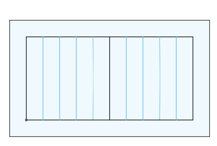
Simple design that allows to calculate the kerf value. The value will be calculated by basing on difference between the design and the real cutted part.
Next thing was to process the DXF file through the software for the lasercutter. Our lasercutter in FabLab is controlled by Ruida controller. For file processing I used RDWorks V8.
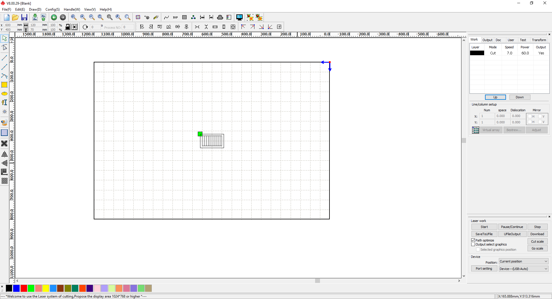
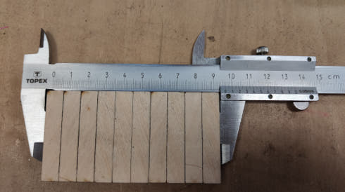
We tested the 6 mm and 3 mm plywood as it is the most used plywood thickness in our lab. For 3 mm we runned the cutting with 30mm speed / 60% of laser power and for 6 mm ,thickness, we used 7mm speed and 60% of laser power. As we got our files ready it is time for running the cutter. But first of all we need to calibrate it. After many test we evaulated that we achive best results with distance of 10mm from material till laser nozzle tip. We even discovered perfect and "profesional" measurement tool. So called "three Festools", as presented on the photo below.
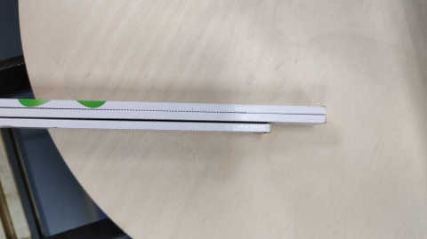
Calibration looks like this:
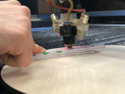
We exactly level the height that the measure fits in the gap between material and laser nozzle tip.
After the machine is all set it is time to run the cutting for both material thicness.
3 mm
How the part looked after cutting: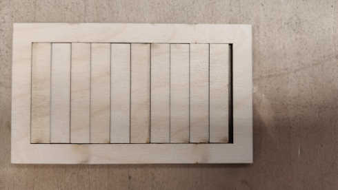
The effect of kerf is clearly visible on this kind of design.
To calculate it we had to measure our cutout rectangles.
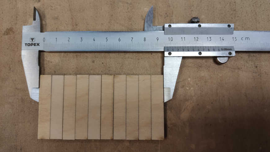
We measured a total thickness of all rectangles , 97,7 mm. We designed them to 100 mm.
It gives us difference of 2.3 mm. Divded by 11 cuts gives us kerf value equal circa 0.21 mm.
6 mm
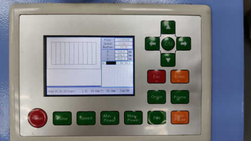
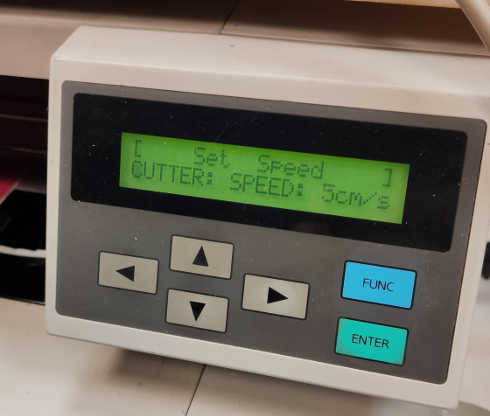
We change the material and runned the cutting again.Photo of the lasercutter panel:
Part after laser cutting:
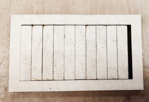
Measurement:
Measured distance: 96,15 mm
Designed thickness: 100 mm
Difference: 3,85 mm
Kerf = Difference divided by numer of cuts
Kerf = 3,85 mm /11 = 0,35 mm
Material testing
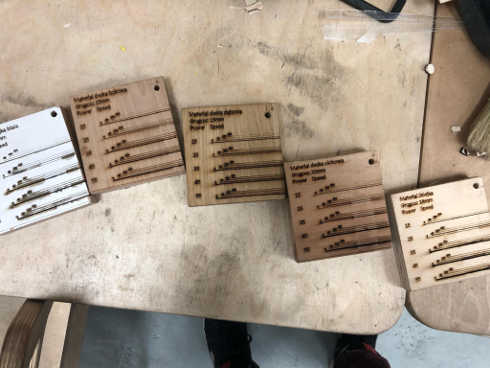
As we already have testes varius of materials in our lab we decided not to duplicte the work.Here are some of our test samples of wood:
Our lab community spreadsheet of laser settings:
Vinylcutting
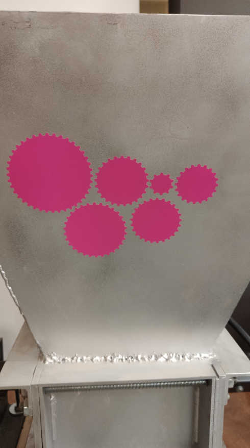
It was my first time to use the vinylcutter. So from the beginning I had a big problem... What should I cut?! Finally, as I am a mechanical engineer, I decided to cut some gears. I used gears generator in Fusion 360, saved their skatches as DXF. But wait! I need ".ai" extension for the cutter software, "Roland Cut Studio". This is when online conventers come handy!I used: Convertio.co
Quite cool site with many options of convertions.
OK, so to the cutter!
Our cutter:
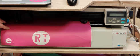
First of all we need to set our material on the machine
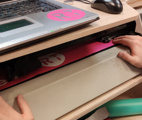
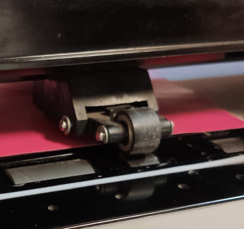
Then we pull down the lever:
The lever is responsible for setting the pressure on the material by rollers:
Now we process the file in the software:
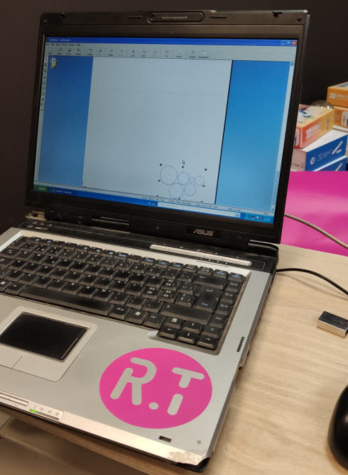
The file is transfered to the machine by LPT connection. Due to the fact that this is our only machine that uses that kind of plug, we have only one laptop that have such socket.
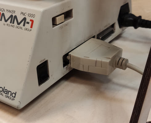
Next to the LPT plug we have a power button and white slider that indicates the force the cutter uses to press the cuting knife on the material. Next we check if all setting on the machine are OK:
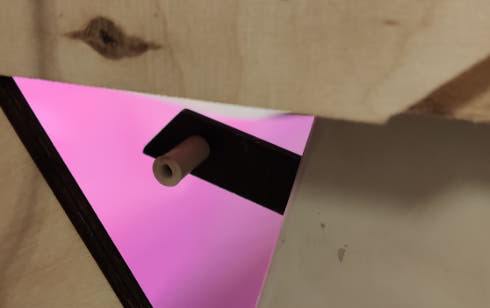
After everyting is nicely cut:
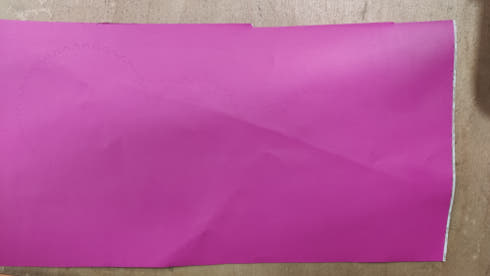
Right now it is hard to see anything on the material but now we sticka a transfer foil on our cutted elements. Than we peel if of so the cutted elements stay on the transfer foil.
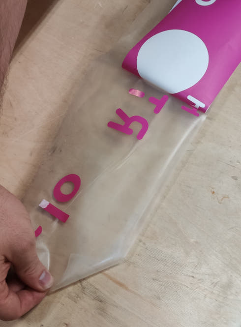
Now we can stick this to any FabLab equipement that we wish to make exeptional!
It was the first time I used the vinylcutter but I am sure I will use it more often right now. This assignment showed me the bacics of its possibilites and I am sure I will discovere more!
Desingning the kit
One of our assignments in week 03 was to design a parametric construction kit that is modular and allows us to create/build structures. It was also important to make it on the lasercutter. To design it I decided to use Fusion 360 as I already know how to use it. First of all I added a parameter that I will use during the designing.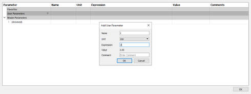
The parameter is called "t" as thickness and it defines the thickness of the plywood I will use to cut the elements for the kit. I started the design with simple arc. First I made two cricles which are concentric.
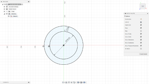
I need only quater of those cricles to make half of an arc, so I added two lines. One horizontal and second one vertical.
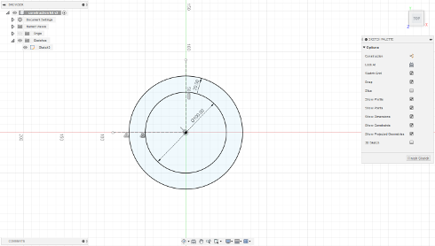
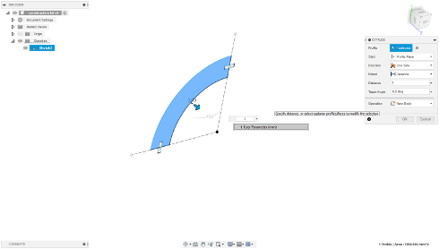
After this I trimmed the 3/4 of the circle, with "Trimm" tool. One last thing to this part was adding fit slot to make it able to be connected with other parts.
I made it by placing a rectangle in the middle of the lines that are on the beginning and end of the arc. Next up, extruding the sketch by the value of thickness parameter.
Now I designed the part that will connect two arcs into one piece. It is a simple square with cuts for press fit joints.
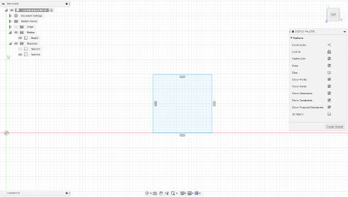
Then I extruded it just like the part before.
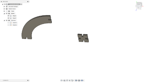
Third part that can be used is a simple rectangle that is 100 mm long and 20 mm wide.
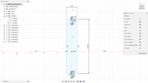
After that I extruded it by the value of "t" which is my parameter of the plywood thickness. While I have all my necessary sketches I can save them as DXF and transfer to RDWorks V8 as it is the software that we use for our FabLab laser. That leads Us to next part "Cutting the kit".
Cutting the kit
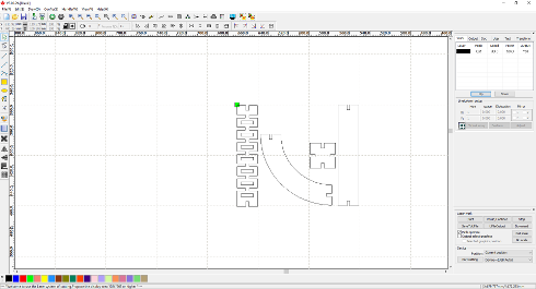
While having the DXF's ready, next step is to prepare the files for laser cutting in the RDWorks software.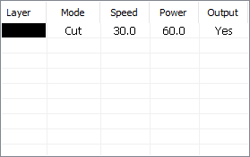
These are our normal settings for 3 mm plywood.
Uplading the DXF file into the workspace.
After this there is a the basic stuff as following:
-uploading the files into the laser
-calibration
-setting the origin
-cutting
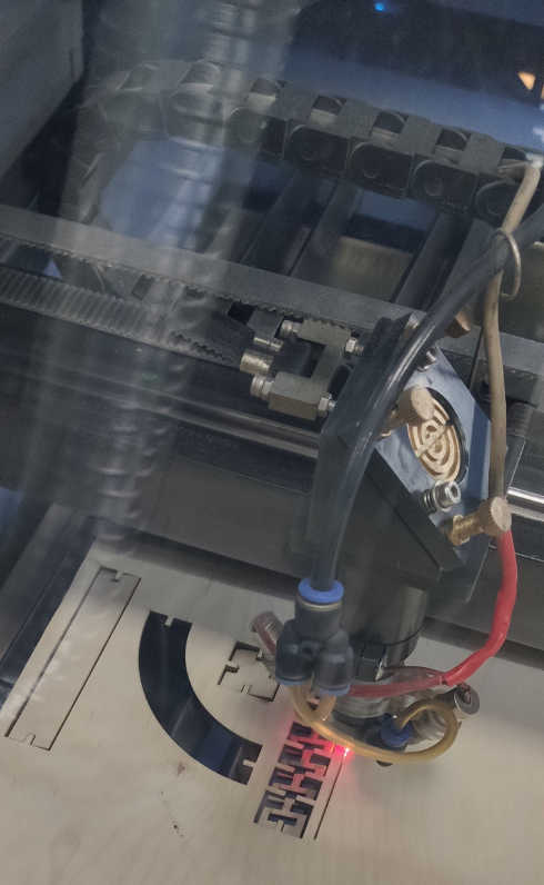
Cutting.
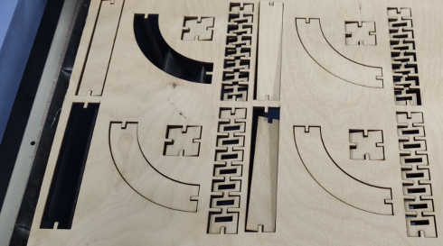
Kit cutted.
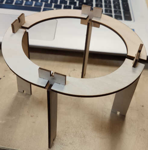
The example construction made with use of the kit.