
Week_16 - Machine and Mechanical design
Assigment
Group assignment:
Group assignment:
The great seek:
The worst tasks are probably always those where you have almost unlimited choice. So this is why we spent a lot of time looking for the perfect project. That's brainstorming sessions when we were throwing away incredible projects and machines like from stark industries, took as a few days.But ok we needed to get real, there are only two of us and our instructor, is not enough for sophisticated machines. So we decided to build something that will be useful in the lab. We thought what kind of machine we don't have and what kind of machine could be useful. It came to a 3d foam cutter. We searched the Internet to see how people build such machines. We found a few examples and started working on our machine. As it wasn't our team that was together most of the elements we did the final project together, Piotr Bejenka put in his site, thanks man!
Below is a summary of our task:
You can find the whole activity on the lab page in Group Assignment and at Piotr's site.
My Contribution
Design Process
SEARCHING
We started designing by searching the elements we have on site in the lab and which could be obtained in Warsaw. Ha Good thing that we don't always manage to finish the projects thanks to that we got a few engines and hot wire, which were parts of lost projects somewhere in the electronic workshop.
Due to the current pandemic situation, we were most afraid of the lack of availability of V-slot aluminum profiles. Fortunately, thanks to our wonderful community and a few phones we managed to buy all the missing elements.
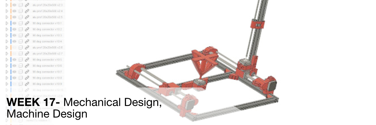
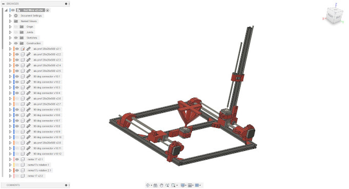
3D MODELING
To make everything work out well we started to move real objects to the 3d modeling program and here, just like last time we used Fusion 360. (You can read more about the features we used in our previous entries e.g.
In the project we focused on strengthening the frame and creating a place in the middle of the table that will allow us to get 3 dimensions while our machine is working.
FRAME
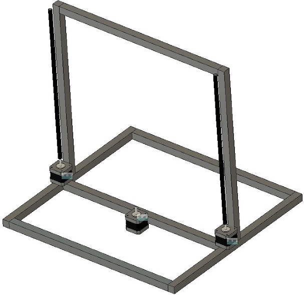
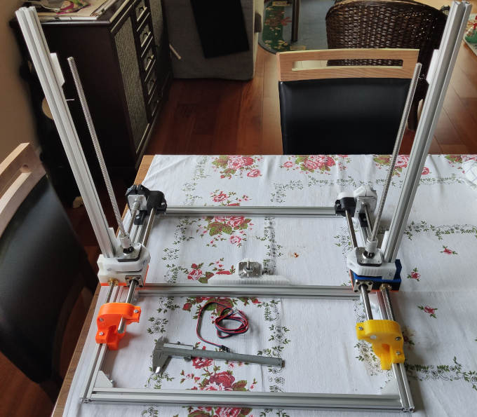
After several attempts and looking at various joints at OpenBuilds , we created a frame, stepper motor connectors and a turntable. So we had practically everything but a problem with the hot wire and its location, but this will be discussed later. For now we have used the design like from the simplest 3d printers such as ENDER 3D or ANET a6.
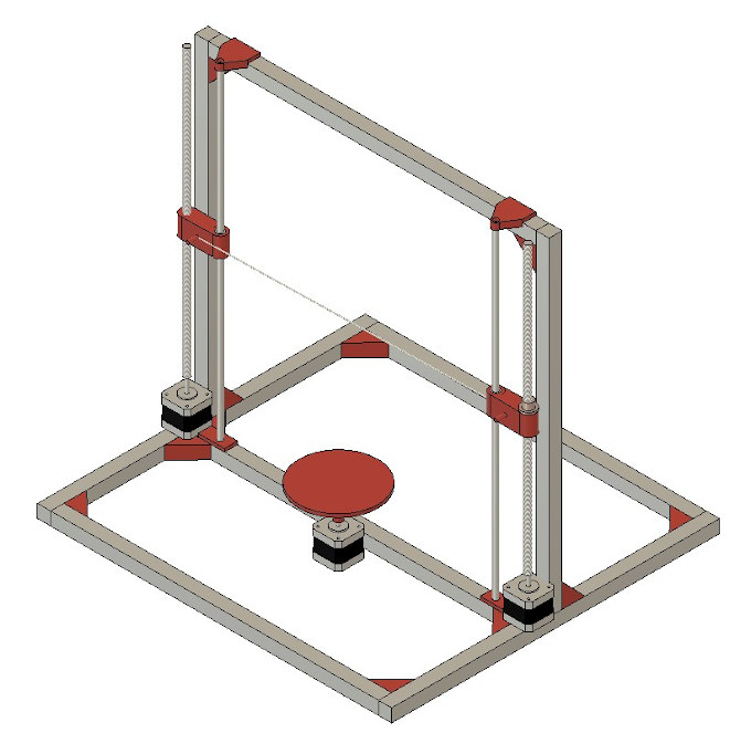
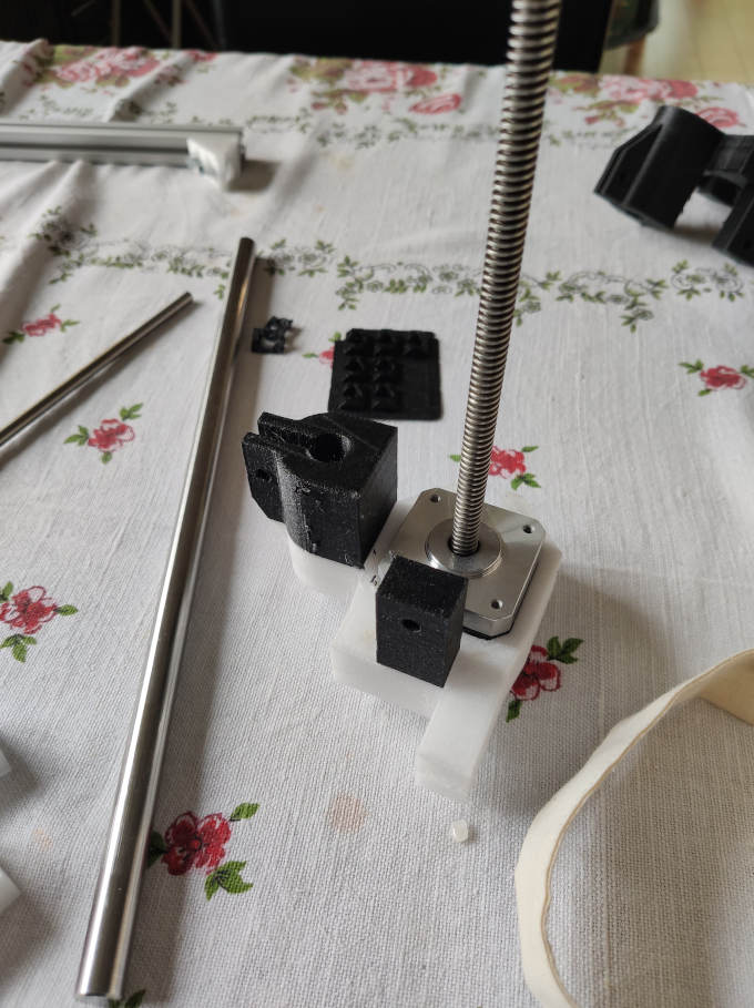
So we placed the hot wire on the nuts and ball screws, which were connected to the motors, and in order not to rotate the nuts, we added tension guide rods to the hot wire. The table in the middle was rotating directly on the engine, with time I think that although there are not too much forces and weights here, it would be better to connect the engine to the table with some belt or transmission.
Test Prints
The next step was to print the elements. To check if everything will fit we printed a test set of connectors on a high layer (0.39 and on a small fill of 10% and increased maximum speed).
RAMPS and Arduino Uno
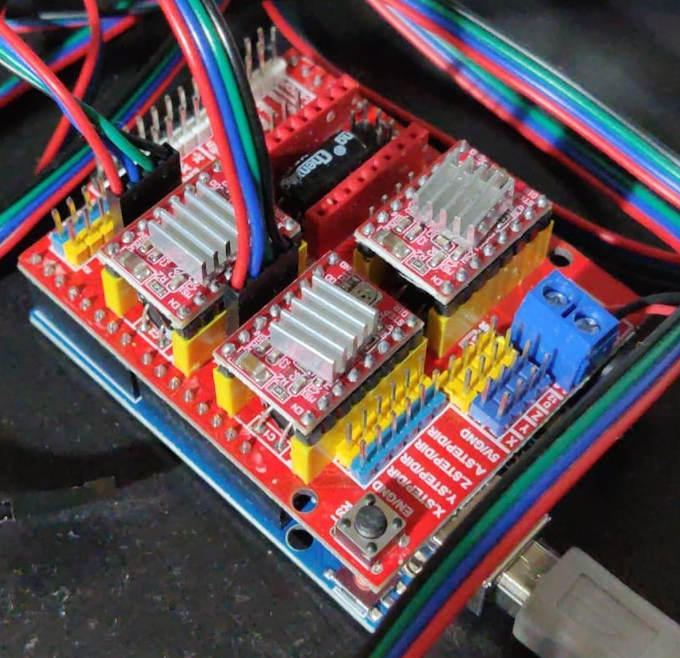
Everything matched... We put the whole set on the printer and we had to wait. But we were not bored, we still had to figure out what to use to control our machine. And here again we used our knowledge from the construction of 3d printers and chose cnc Shield RAMPS and Arduino UNO, which is probably one of the cheapest and best described sets for controlling cnc machines.
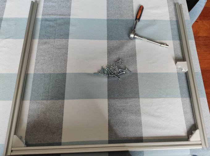
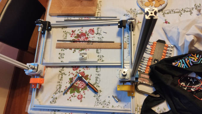
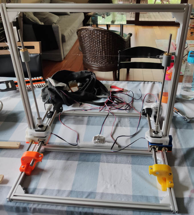
Assembling
Then there was the process of screwing and assembling all the designed elements together. Piotrek took the elements with him and assembled them.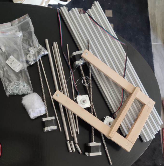
Software
The firmare I will use is the standard Grbl firmware. It can be downloade On this github page . To load the firmware I will use Arduino IDE.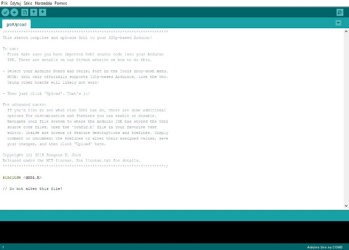
To control the board I will use the Universal Gcode Sender. It is a free software that simply send GCode to any standard machine.
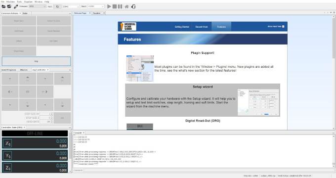
After sucesfully connecting to the machine I can run a setup wizard in which I can configure the entire machine. The most crucial part is calibration.
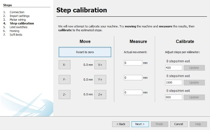
At this point I define the steps that the stepper motor makes for each real life mm of travel. After the calibration and configuration is complete I can generate some gcode to test if machine works properly.
GCode Genereting
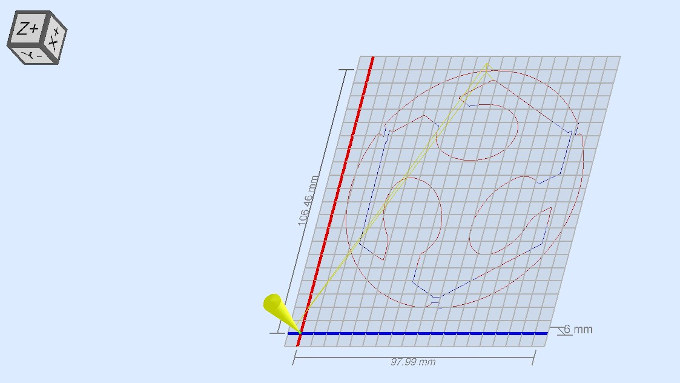
To make the gcode I will use Inkscape. This software containt a plug-in tool that converts the path into gcode. 1st of all I need to set-up the workspace to match my work space. To do it I have to go to File > Document Properties and there Size setting. Set it in mm to be as my work space. Then I can upload any graphic file. I will use FabLab logo.After uploading the graphics I use "Trace Bitmap function" to convert the bitmap into trace. Now I can setup the orientation point and tool for Gcode generation feature. For orientation point I go to Extenions > Gcodetools > Orientation Points and simply press OK. Now for the tool: Extenions > Gcodetools > Tools Library and there I have to select Cylinder . A green window will pop up on the work area.
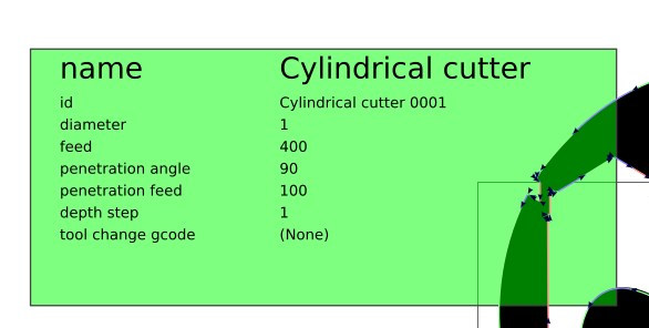
On of the things that have to bo changed is the "Diameter", in standard setting it will have a value of 10. We have to change it into 1 as we have very thin wire as a tool. The last thing in Inkscape is to use Extenions > Gcodetools > Path to Gcode... feature. After using it we will have a .ncg file that we can use in Universal Gcode Sender.
After confirming that the machine works properly I can connect the wire into the main cutting wire to make it hot and run a cutting with foam this time: