Push-Pull
Using Previous weeks of Electronics Production and Embedded Programming for a simple .
Custom Board
To Program my custom board made in the Electronics Production week with AtTiny44a. It has three additions to the basic chip: LED on power, LED on pin and a button on pin.
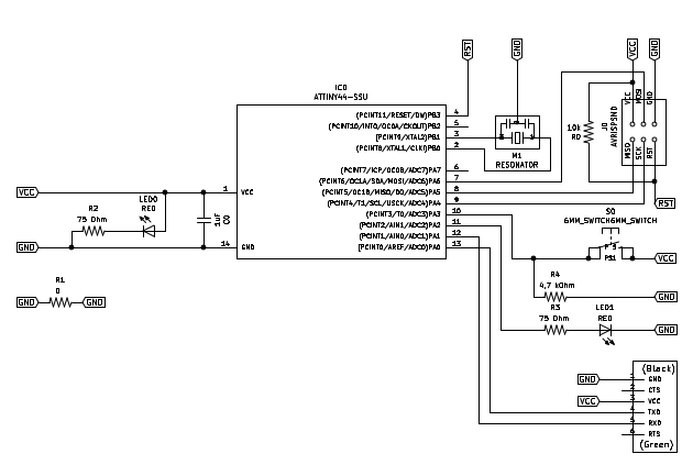 – Schematic of Logic (Corrected) –
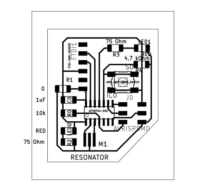 – Schematic of Traces (Corrected) –
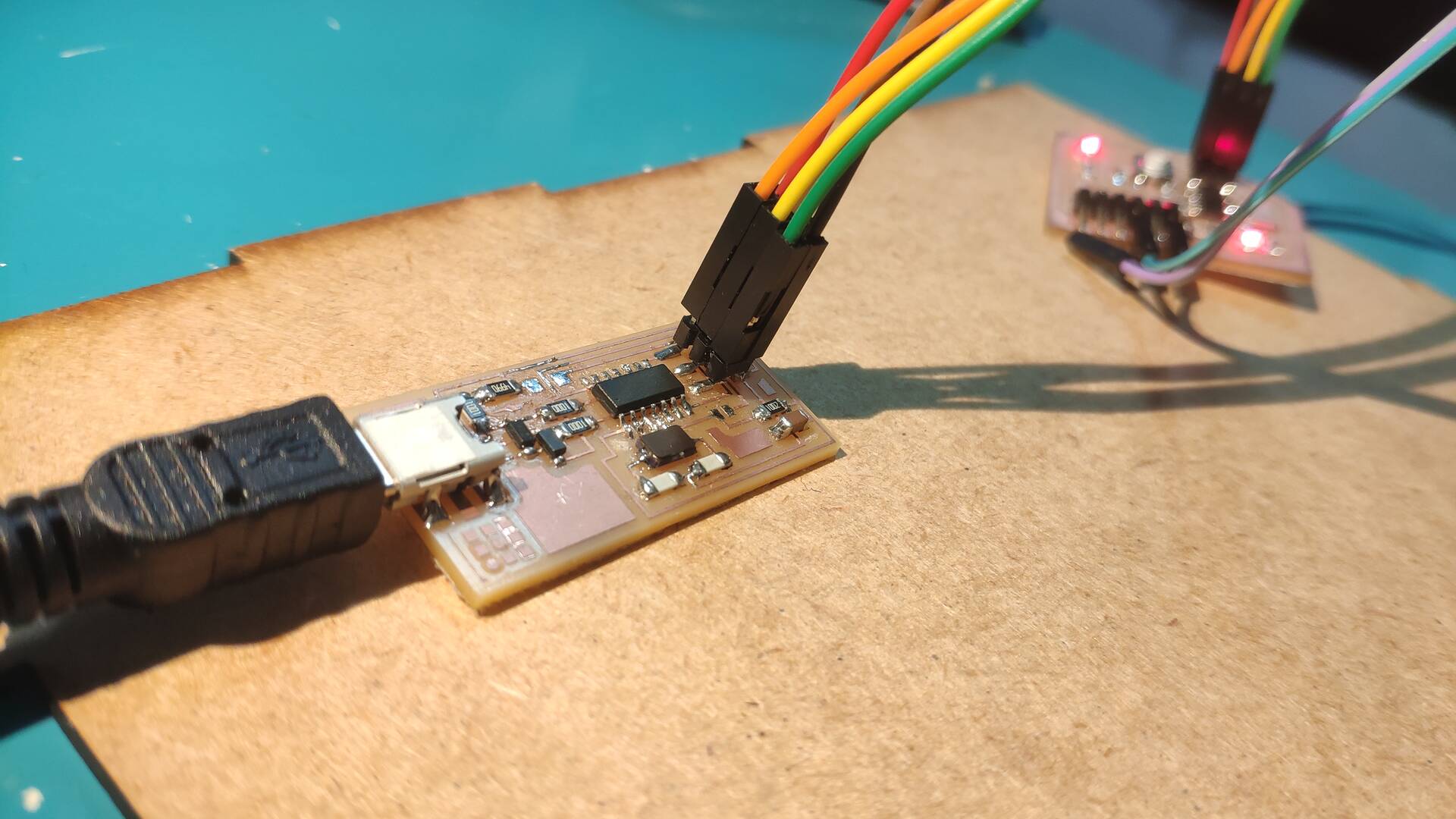
Last week I used Arduino as a programmer for another AtTiny44a on FabISP programmer. So this week I thought I should use it to program my board.
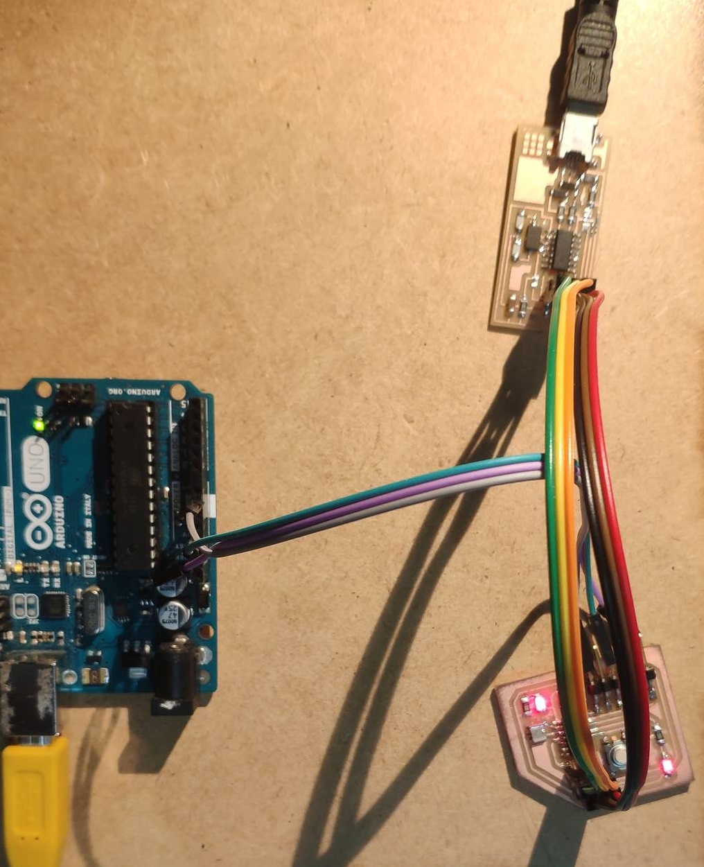 – Programming Setup –
Unfortunately I didn’t have a power supply, nor a working FTDI to USB adapter, so I had to use Arduino as a power supply:
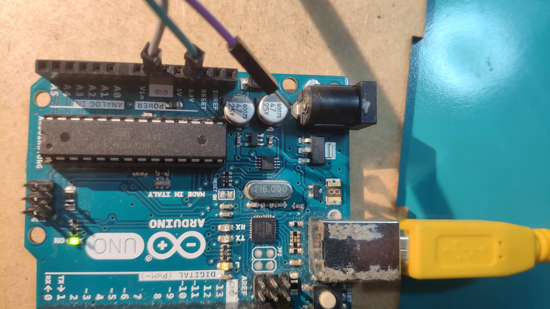 – Power Supply –
Sorry for the visual of my connector - my Arduino lived through a project of my friends two years ago which left a mark on it forever
Step 0. Power
First good sign that my board was good I got when the power got connected the Power LED got lit up. That indicates that at least this part of the circuit is working properly.
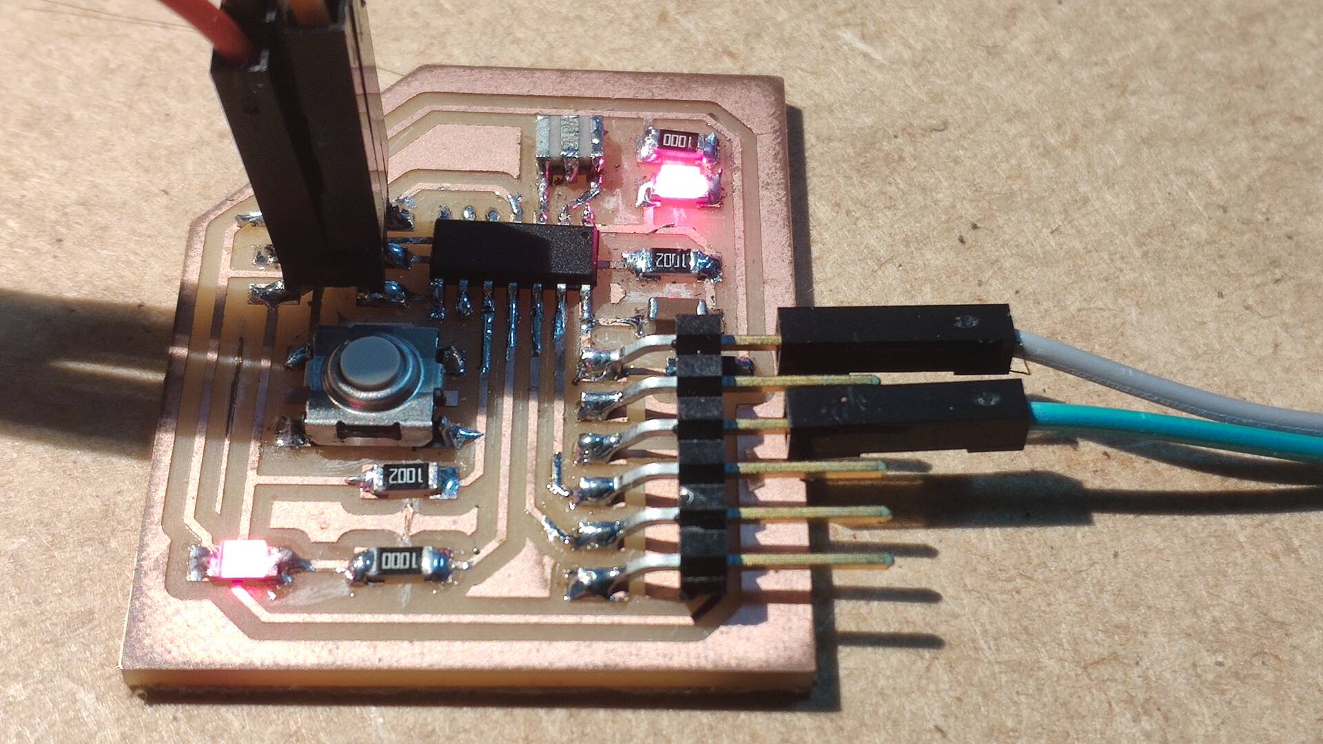 – Power LED –
Step 1. LED
Next step of powering LED went relatively fluidly. After the programmer I had a slight confusion with what has to be done to send commands to a board and what was specific for the programmer.
After messing around I got following conclusions:
- Arduino was used there as programmer - the firmware uploaded to the FabISP is doing same function in this case, as the ArduinoISP code uploaded to it back then.
- Make file is a feature of convenience - it is a kind of a small local dictionary for the command line that allows you to write one command alias instead of remembering all the parameters every time.
- All you really need is a main function in your .c file that you will compile with an infinite loop and this can already be uploaded to a board.
Here is the code I ended up compiling for it:
```c
#include <avr/io.h>
#include <util/delay.h>     /* for _delay_ms() */

// Define Pins used in the board from the documentation and design.
#define PIN_LED 2

/* ------------------------------------------------------------------------- */

// Main loop executed by the controller
int main(void) {
	// Preparation:
	// - Set up LED as output by setting DDRA register.
    DDRA = ((1 << PIN_LED) | DDRA);

	// Main loop:
    while (1) {
		// Blinking
		// - Trun LED on and wait
		PORTA = (1 << PIN_LED) | PORTA;
		_delay_ms(1000);
		// - Turn LED off and wait
		PORTA = ~(1 << PIN_LED) & PORTA;
		_delay_ms(1000);
    }
    return 0;
}
```
And this Code here forth I used in this case too push the code to my board:
avr-gcc -mmcu=attiny44 -Wall -Os -DF_CPU=1000000 -I./ -o main.out main.c
avr-objcopy -O ihex main.out main.hex
avr-size --mcu=1000000 --format=avr main.out
avrdude -p t44 -P usb -c usbtiny -U flash:w:main.hex
 – Blinking LED –
– Custom Board Programmed: LED blink –
Later I realized that the frequency of blinking was too high - because I didn’t indicate to my board that I am using resonator. Didn’t Find yet how to do it.
Step 2. Button
I though I shouldn’t stop there waiting for input week and take the full advantage of the board I have now - and control LED with a button. Button however took a lot more debugging.
The final error turned out to be in the wiring. My button was connected to the Ground and Pull up resistor to power where as it should have been in reverse. This made it so that the signal was always read as on making it not react to the button at all.
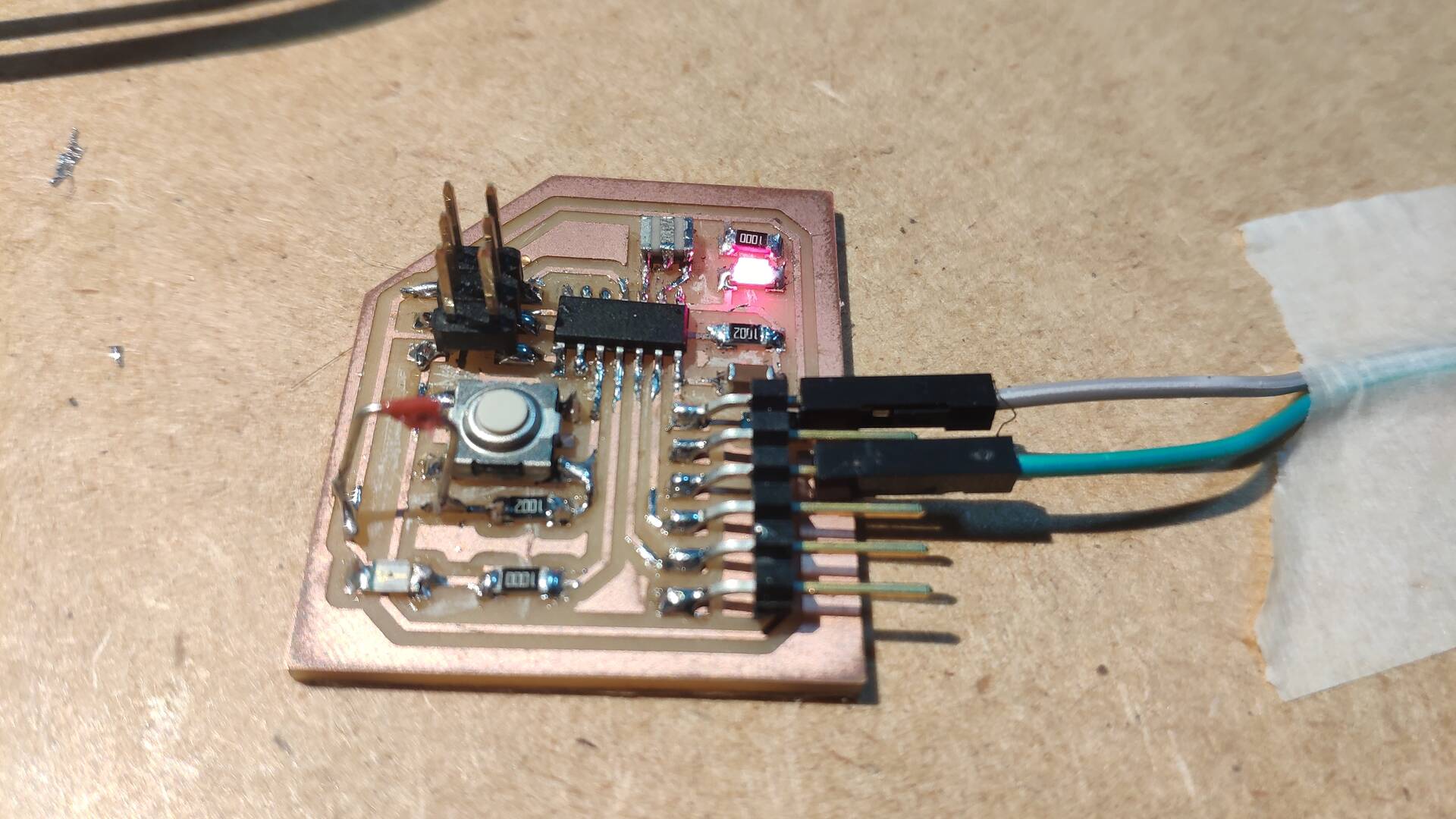 – Custom Board Temporarily Rewired –
 – Inner Cut (Corrected) –
 – Outer Cut (Corrected) –
After this correction which required breaking to traces and soldering an improvised jumper, the code worked perfectly. The code for it was as follows:
```c
#include <avr/io.h>
#include <util/delay.h>     /* for _delay_ms() */

// Define Pins used in the board from the documentation and design.
#define PIN_LED 2
#define PIN_BUTTON 3

/* ------------------------------------------------------------------------- */

// Main loop executed by the controller
int main(void) {
	// Preparation:
	// - Set up button as Input (turn on pull up resistor).
	PORTA = ((1 << PIN_BUTTON) | PORTA);
	// - Set up LED as output by setting DDRA register.
    DDRA = ((1 << PIN_LED) | DDRA);

	// Main loop:
    while (1) {
		// Turn on LED with a button:
		// - Check if button is pressed by reading corresponding bit from PIN and checking if it has been drained.
		if ((PINA & (1 << PIN_BUTTON)) == 0) {
			PORTA = ~(1 << PIN_LED) & PORTA;
		}
		else {
			PORTA = (1 << PIN_LED) | PORTA;
		}
    }
    return 0;
}
```
Result
This was a fruitful exercise in trying to strip all the excessive tools, programs and layers of abstraction this mystical world of electronics programming consists of. By starting with such a barebones example - less than 20 lines of code and four commands - now I start to understand what is this toolchain consist of and how can I do some of the steps in other environments like in Arduino as alternative.
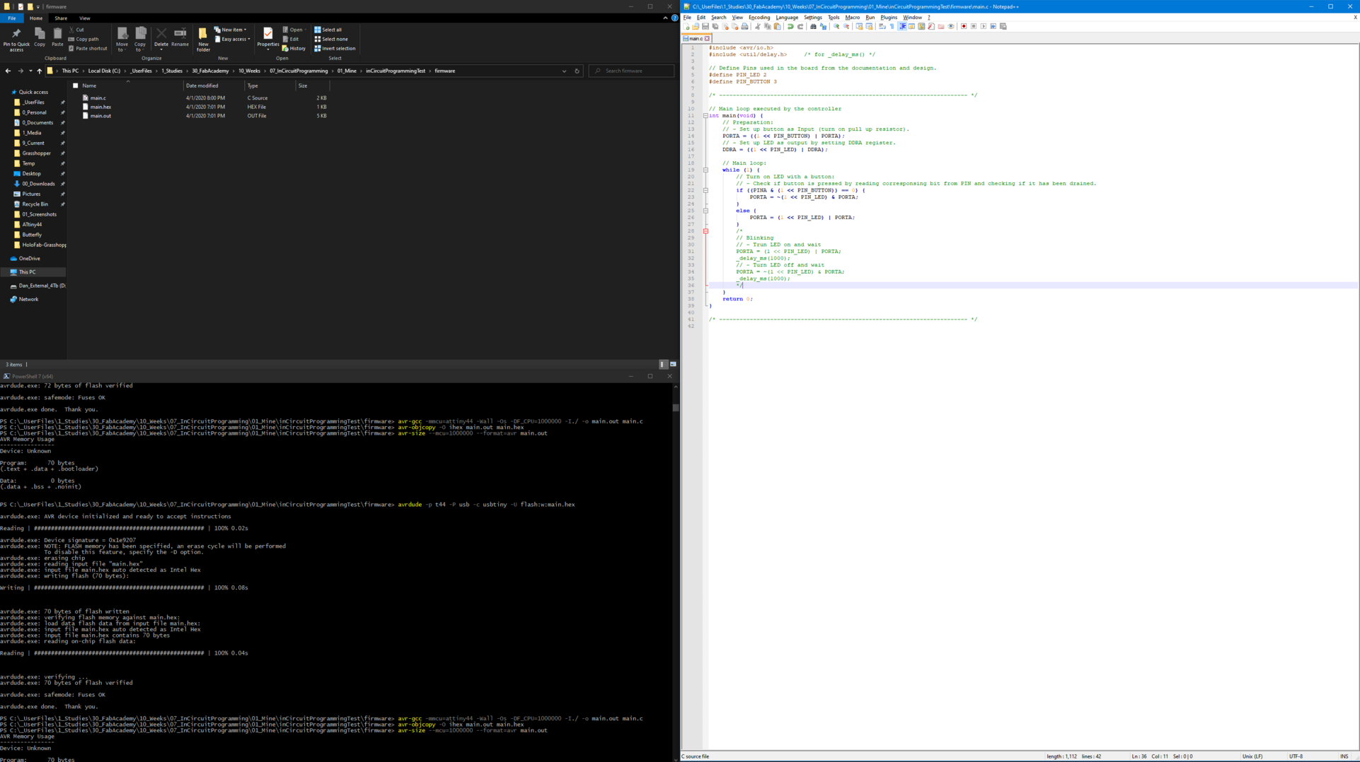 – Custom Board Coding File –
– Custom Board Programmed: LED on button push –
// TODO: Try to do the same completely in Arduino IDE but program through FabISP and also as comparison through Arduino. Compare sizes
Light Sensor
One fascinating concept Neil mentioned in the class that I found quite hard to believe so I wanted to test it myself was the idea that the LED can be used as a Light sensor if used in reverse.
Normally in the package for Arduino an LED is connected with a long leg towards the pin (and I am not writing it here just to document - but rather because I am forgetting it every single time I connect an LED). TODO: explain the diod and how light is emmited and how in reverse it would read the light
This is pretty easy to test so I built a small Arduino test schematic with one LED and a resistor of 220 ohm on one end going to a digital pin which I set as output to HIGH to push power through it and on other connect to an analog pin to read it’s value.
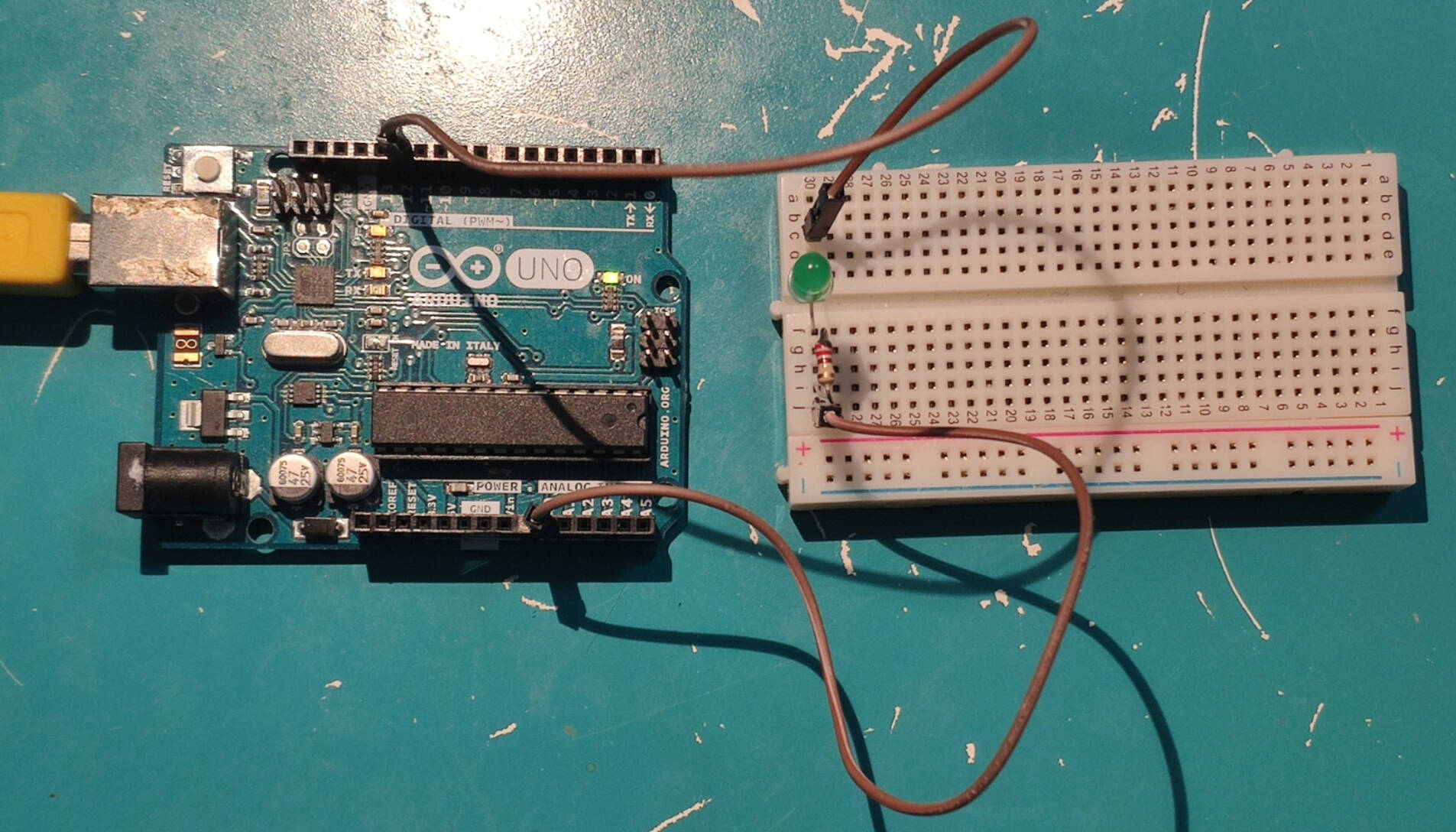 – LED as light sensor setup –
Here is the code I used for this simple setup:
```c
const int writePin = 12;
const int readPin = A0;

void setup() {
  Serial.begin(9600);
  pinMode(writePin, OUTPUT);
  digitalWrite(writePin, HIGH);
}

void loop() {
  int value = analogRead(readPin);
  Serial.println(String(value));
}
```
.png) – LED as light sensor readings –
– LED as light sensor readings –
.png) – LED as light sensor readings –
– LED as light sensor readings –
– Custom Board Programmed: LED on button push –
TODO: add the noise reduction
Arduino Sensor Kit
To be continued . . .