Mechanical Design + Experimentation
In this page, I will describe the iterative mechanical design and sexperimentation that I go through before I confirm the details of the design of the based and stand, the up-down mechanism, the electronics design and putting all of them together.
Initial Base and Stand Design and Experimenting with Servo Motor
I started with my original design of the box/base and stand as shown in the pictures below.
This design was conceived with the idea od having the servo motor connected to a wood rod that will move the tea bag up and down.
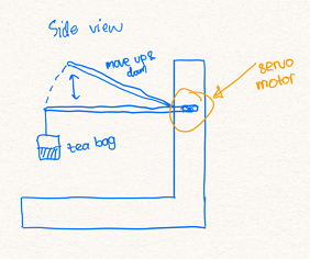
By measuring the dimensions of mug/tea cup, I sketch the design as shown below.

I design the base and stand using Fusion 360. I continued with the design of the box that I did in exercise 2. I added one small hole on the box for the cables to enter the box. I also draw the stand with a height appropriate for the tea bag to hang on a rod and move in and out of the mug/cup. The design drawing in fusion 360 is shown below.
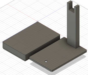
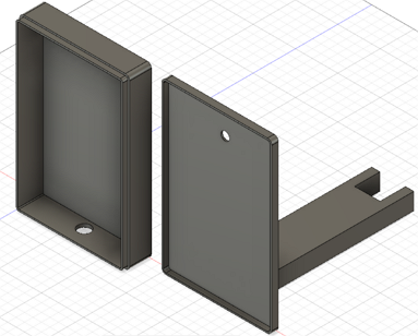
to download the fusion360 .f3d file
to download the fusion360 .stl file
After done with the design, I immediately experimented with servo motor to foresee any challenges I will face with the current design of base and stand when servo motor is used.
Experimenting with servo motor
I refer to my work in Exercise 11. on Output devices especially the servo motor. I was still using the Arduino board since SP fab lab is still closed due to COVID-19. I connect a chapstick on to the shaft of the servo motor. The length of the chopstick is rougly 18 cm and the distance from the shaft onto the te bag is 16cm.

I use the same Arduino code in exercise 11 but I vary the angle to 45 degree and 30 degree because I want to experiment various angles and observe the up and down mechanism.
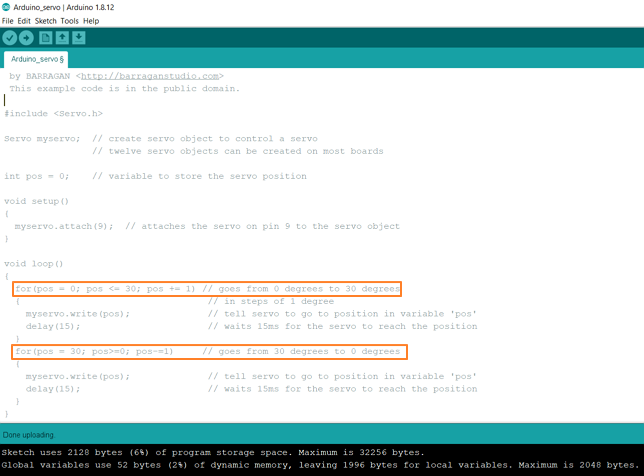
The video below is when the angle is set to 45 degree. It can be seen how the tea bag moved eratically and often not able to move down and enter the mug.
The video below is when the angle is set to 30 degree. It can be seen how the tea bag moved less eratically compared to 45 degree but there were instances where it didn't move down smoothly and enter the mug, i.e. the tea bag hit the lid of the mug.
With these observation where often the tea bag didn;t move down and enter the mug smoothly hence besides the tea extraction process becomes ineffective, this could also lead to spill of the tea drips around the mug/cup, I started to thinker on a new design.
Base and Stand Design Version 2.0
With the challenges mentioned above, I modify the design of the base and stand as shown below:
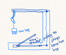
I will use fishing line/string that are attached to the rod on the servo motor on one end and at the other end is attached to the tea bag. With this design, I can have the movement of the tea bag to be always above the mug/cup as such the dripping water will not spilled all around the base. I design the new base and stand using Fusion 360 as shown below.
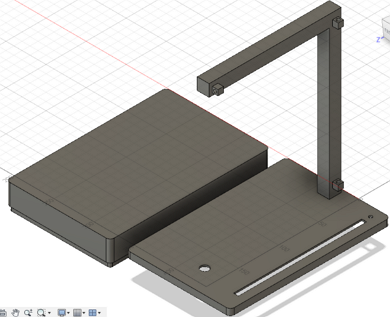
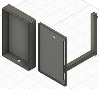
to download the fusion360 .f3d file
to download the fusion360 .stl file
Mechanical Design for mounting temperature sensor DS18B20
The next mechanical design that I need to think is how to bring the temperature probe DS18B20 to be submerged into the water to sense the temperature and send the data to the PCB that I will make.
For this, I decided to use a rack and pinion. A rack and pinion is a type of linear actuator that comprises a circular gear (the pinion) engaging a linear gear (the rack), which operate to translate rotational motion into linear motion. Driving the pinion into rotation causes the rack to be driven linearly.
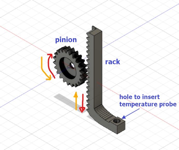 This mechanism will be installed on top of the stand where the temperature probe will go down and submerdged into the water to start the measurement and at the end of the tea preparation, the temperature probe will rise up from the water hence user can grab and take the cup/glass of tea easily.
This design is similar to the mechanical design I used for the group work in Machine Building exercise.
The driver to turn the pinion will be servo motor. Since the temperature probe is quite light, hence a mini servo motor FS90 is sufficient to do this.
In conclusion, I will be using 2 FS90 mini servo motors for this project:
1. One servo for the tea bag to move up and down mechanism and
2. Another servo for the temperature probe to move down at the start and up at the end.
Since the temperature probe will require a servo motor that will rotate the pinion, hence the servo motor must be mounted next to the pinion.
With this new design, I must modify the base and stand design version 2.0 above.
Base and Stand Design Version 3.0
With the new design for the mounting of temperature sensor, I added a stand to attach the pinion and rack on to it. And to mount the various parts, I planned to use 3mm screws hence I created holes by aligning the parts that I want to join including the servo motor FS90.
to download the fusion360 .f3d file for the pinion + rack + bar stand + housing
to download the stl file for the pinion + rack + bar stand + housing
The parts shown above consist of:
1. Pinion
2. Rack
3. Housing for the rack
4. Enclosure for the housing
5. Bar stand
In order for the bar to stand firmly on the base, I need to slot the bar to the top of the base and grip it on the bottom of the base. Hence I came up with the below design.
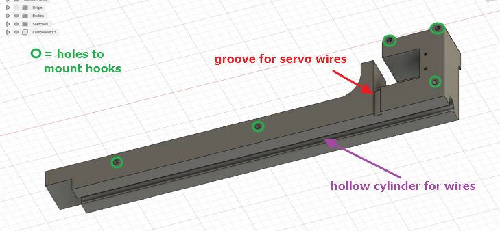
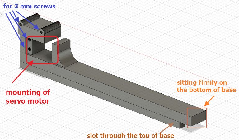 And for the strings, I will use metal hook mounted on the side of the bar stand. To hide the wires of servo motor and temperature sensor DS18B20, I created a hollow cylinder at the back side of the bar stand.
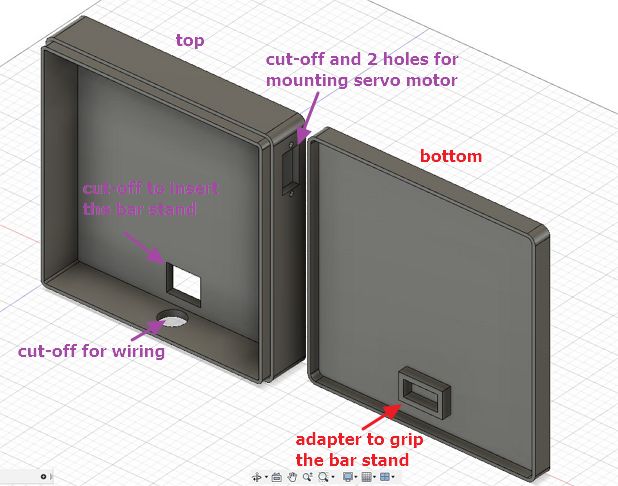
As for the base box, I change the dimension into 150mm x 150mm with a height of 30mm and thickness of 3mm. I added at the bottom of the base an adapter to grip the bar stand.
I also added cut-off and 2 holes for mounting the servo motor and a circle cut-off for wiring purpose.
to download the fusion360 .f3d file for the base design
to download the stl file for the base bottom design
to download the stl file for the base top design
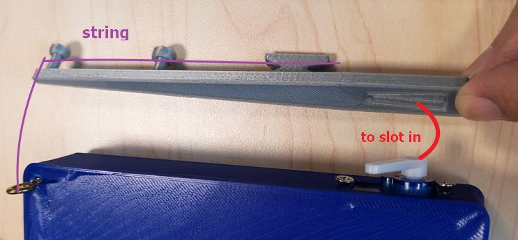
Next, I also design the arm extension for the servo motor that will move the tea up and down.
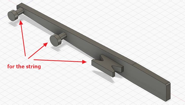 On one side I added protruding parts where I can coil the strings.
 While at the other side, I added a small cut-off to insert the servo motor shaft according to its real dimension.
to download the fusion360 .f3d file for the arm extension of servo motor
to download the stl file for the arm extension of servo motor
And this is the final design:

to download the fusion360 .f3d file for design version 3.0
to download the stl file for the design version 3.0
3D Printing Base and Stand Design Version 3.0
I used 3D printing to make version 3.0.
One thing to note is that for the top of the base I used ABS filament because it can withstand temperature up to 100 degree Celcius unlike PLA.
To use ABS filament, I will use a different 3D printer compared to past weeks exercises which is the CUBICON 3D printer. The model that I use is CUBICON STYLE
![]() The slicing software used is also different (for Ultimaker, I used CURA slicer). The slicer software CUBICREATOR4 can be downloaded from here.
The slicing software used is also different (for Ultimaker, I used CURA slicer). The slicer software CUBICREATOR4 can be downloaded from here.
In the cubicreator software, I set the filament as ABS as shown in the below picture.
![]() Then the cubicon model set in the slicer, which is Cubicon style 3DP-210F is shown below:
Then the cubicon model set in the slicer, which is Cubicon style 3DP-210F is shown below:
![]() Note that the bed size is 150 mm x 150 mm x 150 mm which is just nice for printing the top of my base design. While the nozzle temperature is up to 260 degree Celcius.
Note that the bed size is 150 mm x 150 mm x 150 mm which is just nice for printing the top of my base design. While the nozzle temperature is up to 260 degree Celcius.
The operation of the slicer is very straighforward, after opening the .stl file in the software, I just need to click "prepare"
![]() Once inside the "prepare" window, using the default setting, I clicked the "save to G-code" to generate the toolpath and then save the toolpath into a SD card and ready for printing.
Once inside the "prepare" window, using the default setting, I clicked the "save to G-code" to generate the toolpath and then save the toolpath into a SD card and ready for printing.
On the machine itself, it does auto leveling hence I only need to start the printer and select the file that I want to print.
![]() The rest of the part I printed using the Ultimaker 2+ printer. The printed results are shown below:
The rest of the part I printed using the Ultimaker 2+ printer. The printed results are shown below:
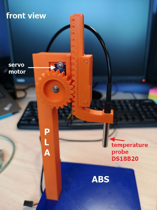

The bottom base (grey color) is printed using PLA and some part of the surface is bit wavy due to the setting of the infill that I used in slicer is too low (5%) but it still works because the most important part is the adapter to grip the bar stand.
 As for the arm extension for the servo, I am very happy that the dimension I have drawn in Fusion 360 is very precise and can snug in tightly into the servo motor as shown below.
 And after assembling all the parts, this is how it looks like:
