TING's final project
Design Process - Project Phases
I divided the project into 6 major parts as follows:
- Research on and carry out testing on Microbial Fuel Cell (MFC) to finalise the MFC structure (proton exchange membrane (PEM), electrodes and electrolytes)
- Mechanical Design (1) - Design & make the MFC chamber
- Mechenical Design (2) - Design & make the housing for the electronics
- Mechanical Design (3) - Design & make the Floating mechanism
- Electronic Design - Design & make the electronics
- Design the App or program
Part 1: Literature Review and testing of the MFC
This is ongoing and will be updated in the "Notes" section from time to time
Part 2: Design & make the MFC chamber
From the conceived final product, I identify the different parts of the MFC chamber. The parts are listed as follows
- Top housing for the electronics
- Anode chamber (needs to hold oxidizing aqueous chemicals such as KMnO4)
- Proton Exchange Membrane holder(must prevent liquids from both sides from mixing)
- Cathode chamber (allow wastewater to enter and leave)
The plan is to use 3D printing to make the MFC chamber although there are several websites that state that PLA (Polylactic acid) will swell and breakdown when immersed in water for prolong period of time. According to 3dfizzr.wordpress.com, it is PVA (Polyvinyl alcohol), not PLA that breakdowns in water.
I tested this out myself by placing a PLA 3D printed part in my aquarium for 4 weeks and monitor its condition every 4 days. The results are on the next page
The second issue of using PLA or rather 3D printing to make the chamber of holding liquid is the porosity of the printout. It is well-known that 3D printed parts tends to be porous and are hence not suitable for holding liquid or gases under pressure. Most websites would recommend applying clear epoxy such as Alumilite Amazing Clear epoxy to make the printed parts water-tight or even air-tight.
An article on Instructables.com suggests that by optimising the slicer setting and experimenting with various slicer programs, it is possible to print objects with a standard filament printer that will hold water or air under pressure.
Below are water-tight and air-tight 3D printouts from Instructables.com website
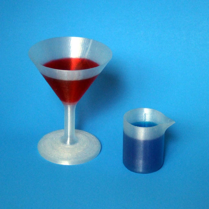
3D printed martini glass and beaker holding colored water
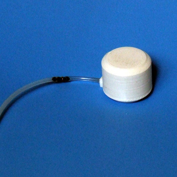
Small 3D printed air pressure tank
While playing with slicer setting and infill is challenging and fun, I need to be realistic about time constraint, hence I decided to use coating to seal and reduce porosity. For my application, I do not need the 3D printed chamber to be air-tight and maintain the pressure for a period of time, instead I am more concern about moisture permeability. I plan to design and 3D print a simple air chamber, apply polyurethane coating and test the moisture permeability using mass change in silica gel over time. Results are presented on the below.
Test Conducted and Results
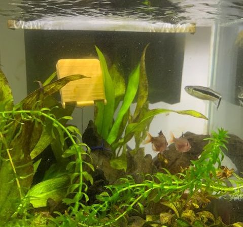
Water Immersion test on PLA printed part
Several websites claimed state that PLA (Polylactic acid) will swell and breakdown when immersed in water for prolong period of time. 3dfizzr.wordpress.com, however argued that it is PVA (Polyvinyl alcohol), not PLA that breakdowns in water.
A test was carried out by placing a PLA 3D printed part in my aquarium for 4 weeks and monitor its condition every 4 days.
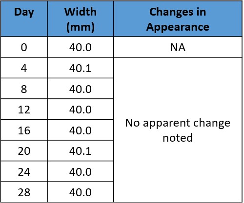
No apparent change in dimension nor appearance is observed suggesting
that PLA is water tolerance and can be used to make the housing for the
electronics
Moisture Permeability Test
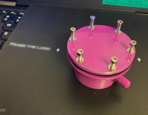
To measure moisture permeability, this is what I planned: design a small chamber and 3D print it. Weigh and put 20g of fresh silica gel in the chamber. To ensure that the cover is tight, a rubber gasket is sandwiched between the chamber and the cover and held down by 6 bolts and nuts. The chamber is then placed in closed container that is filled partially with water. The control is a small glass bottle containing the same mass of silica gel.
After 3 days, both the control and the chamber will both be retrieved, wiped dry with a tissue paper and weigh. After weighing, the chamber and the glass bottle will be placed back in the dessicator. The weighing will be repeated every 3 days for 2 weeks.
Till date, I have completed designing and printing the chamber, found the gasket, the screws and the bolts.
The next step is to carry out the test. I measured and placed about 25 gram of fresh silica gel in the chamber
Click to download STL file
Click to download Fusion 360 file
Test on Microbial Fuel Cell
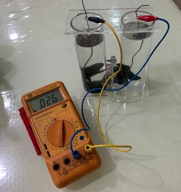
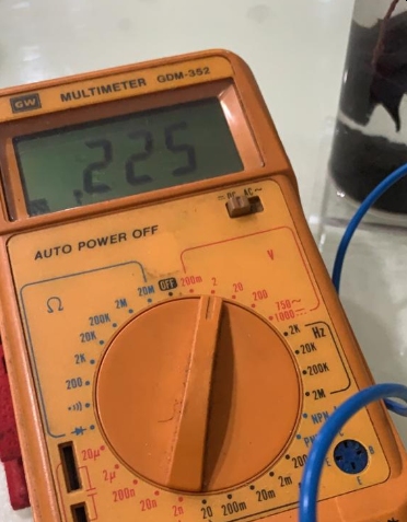
A setup was borrowed from the laboratory. Saturated salt (sodium chloride) solution is placed in the cathode compartment. For the anode compartment, aquarium water together with some planting media was used. A voltage of 0.225 volts was obtained. With dirtier water, this voltage is expected to be high but should be around 0.5 to 0.6 volts according to research data.
Next to Project Schedule