
Week 8
Embedded programing
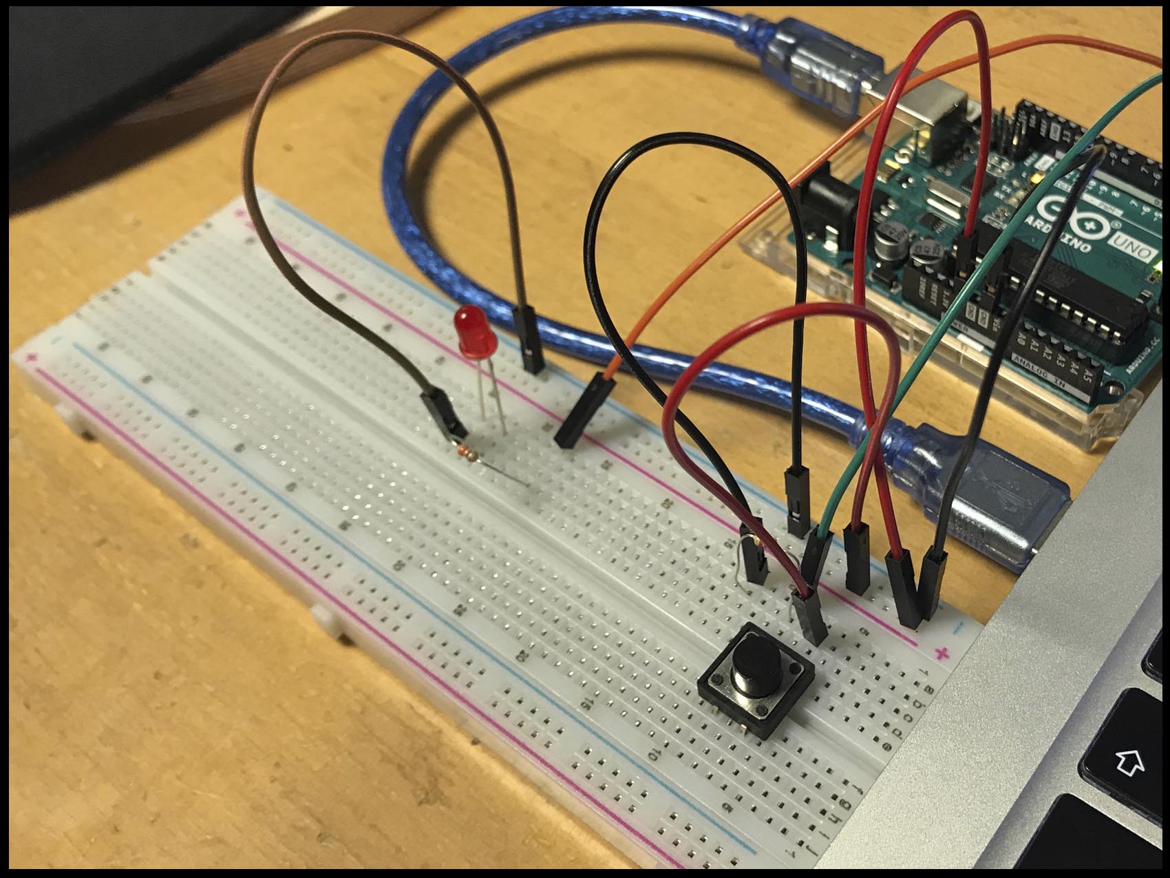
Coming back to the electronics programming. It is time to take is slowly and set the basics starting for the microcontroller. During the rest of the assignments and final I will work with ATTINY44D, ATTINY45, ATTINY3216 ATTINY1614 and ATMEGA328p. The election depends on how many pins I need to use. Because of this variety of microcontroller I used to program ISP or Arduino NANO. Overall for ATTYNY1614 and ATMEGA.
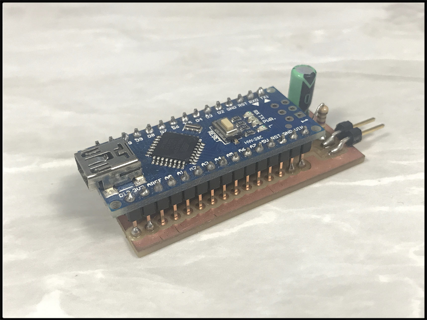
Getting to know the function and basic of the ATTINY I discovered that where design on 2016 to replace their older ATmega and ATtiny. Until recently new chips were not accessible to users of the Arduino IDE, because no Arduino core existed for them, and it was no possible to program them using the ISP programmers. That changed a couple of months ago when Spence Konde released a megaTinyCore for the new range, taking advantage of the work Arduino have done to support their new ATmega4809-based boards.
Coming back to our issue, the new parts like our microcontroller are numbered with the series number on the middle:
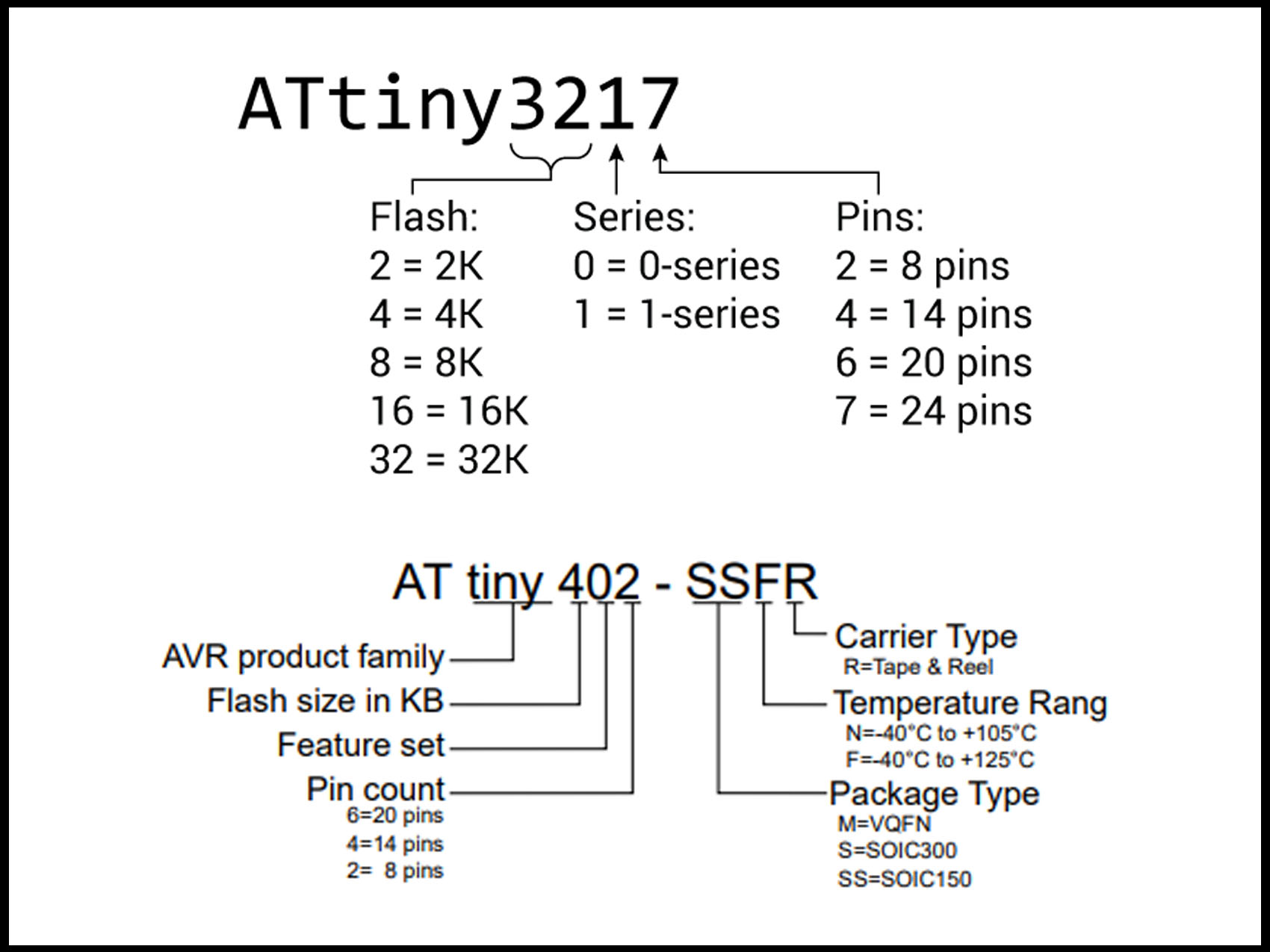
The first digit of the numbers that comes after the designation ATtiny makes sense, it is the amount of flash memory in kibibyte and the second is the model type. However, they are not chronological.
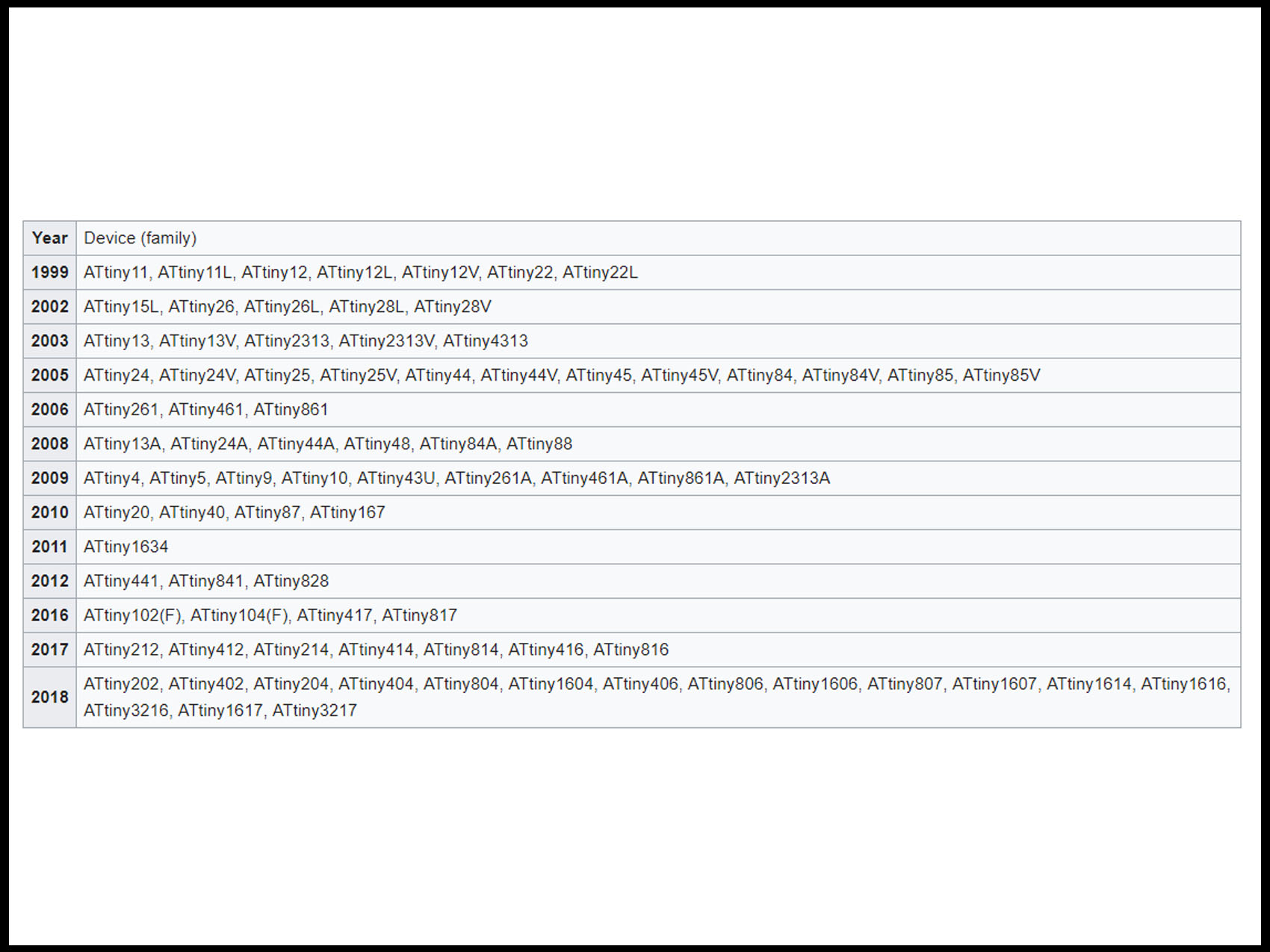
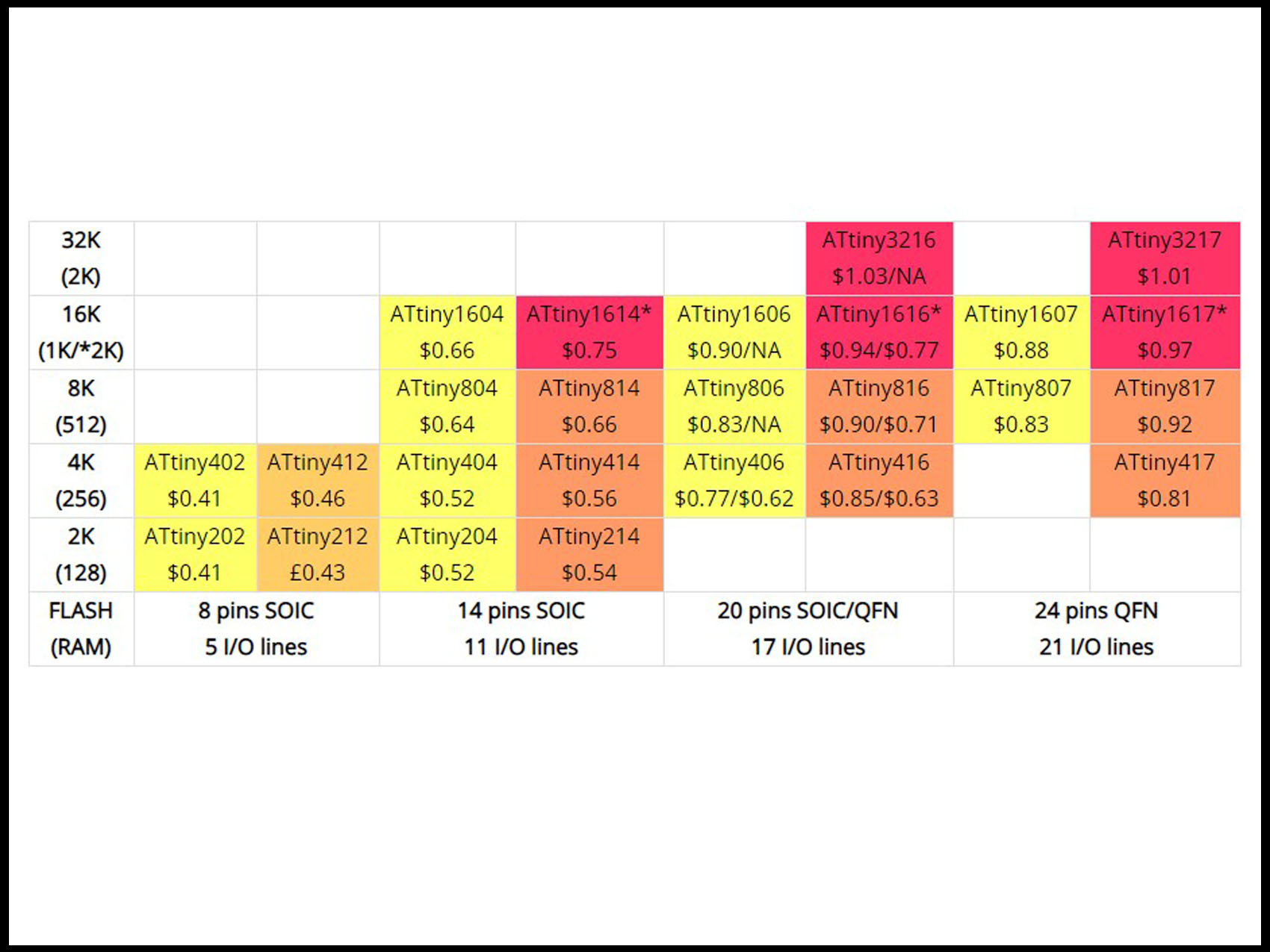
The ATiny chips form a consistent matrix of devices and they are described in several separate datasheets, that you need to read if you want to get an overview of their capabilities and differences. A sum up classify by flash sizes and number of pins could be:
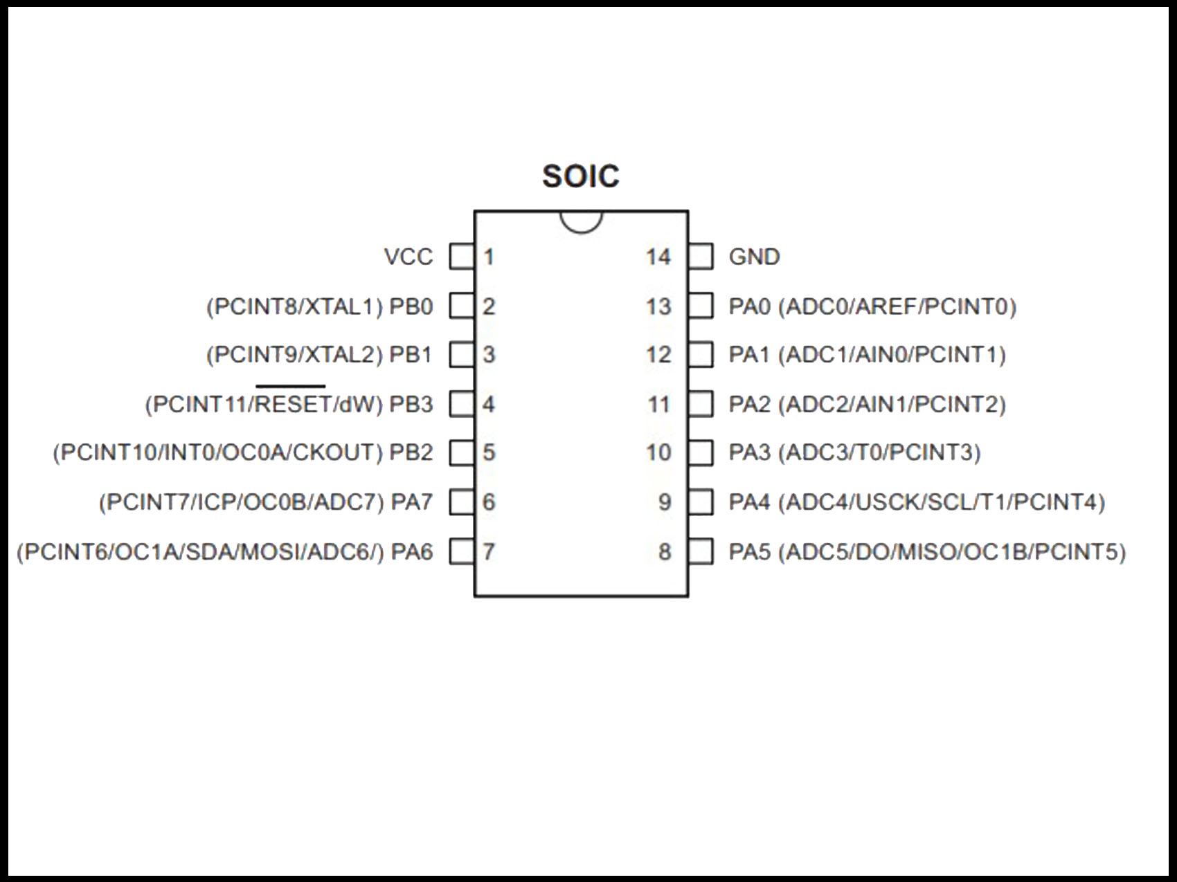
The pins are divided on:
- VCC. Supply voltage. GND. Ground.
- Port B (PB3...PB0). Internal pull-up resistor.
- RESET. Reset input.
- Port A (PA7...PA0). Input and analog input for the ADC, analog comparator, Time/Counter, SPI.
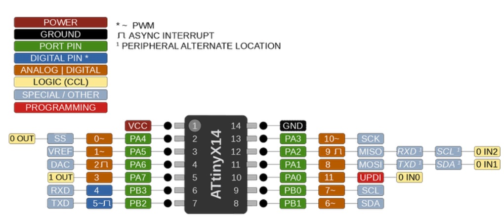
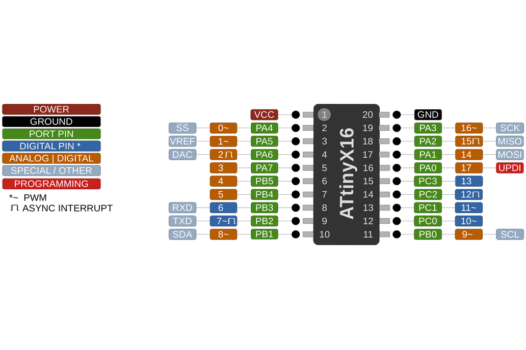
To program the board, I use Arduino. Before going through the setting of Arduino to program the board it is necessary to take a look on the following information about the pins:


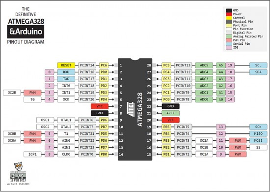
We already use Arduino before on week 3 and week 6. Anyway, it is good to take a look again and learn more with the language reference. and practice how to write the sketches:
- /* Comment
- // Comment
- int for variables of the pin.
- Functions and pinMode(), digitalWrite(), delay()
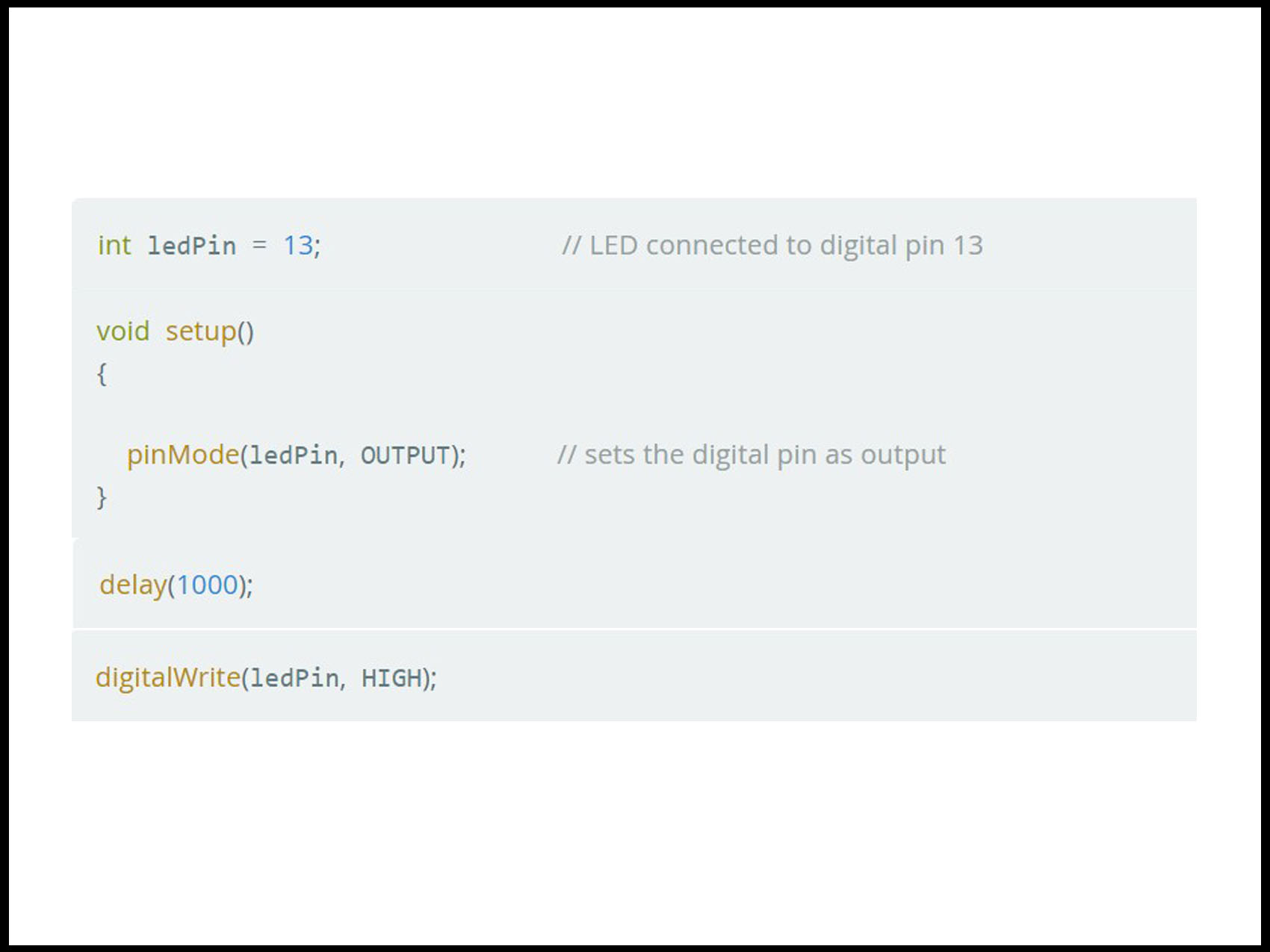
I practiced a little bit with my Arduino Kit and some sketch, to see if I am able to send orders to the board and, even if Arduino check before you, it is also good that you read over because it is so common to forget the “;” to close and nothing work.
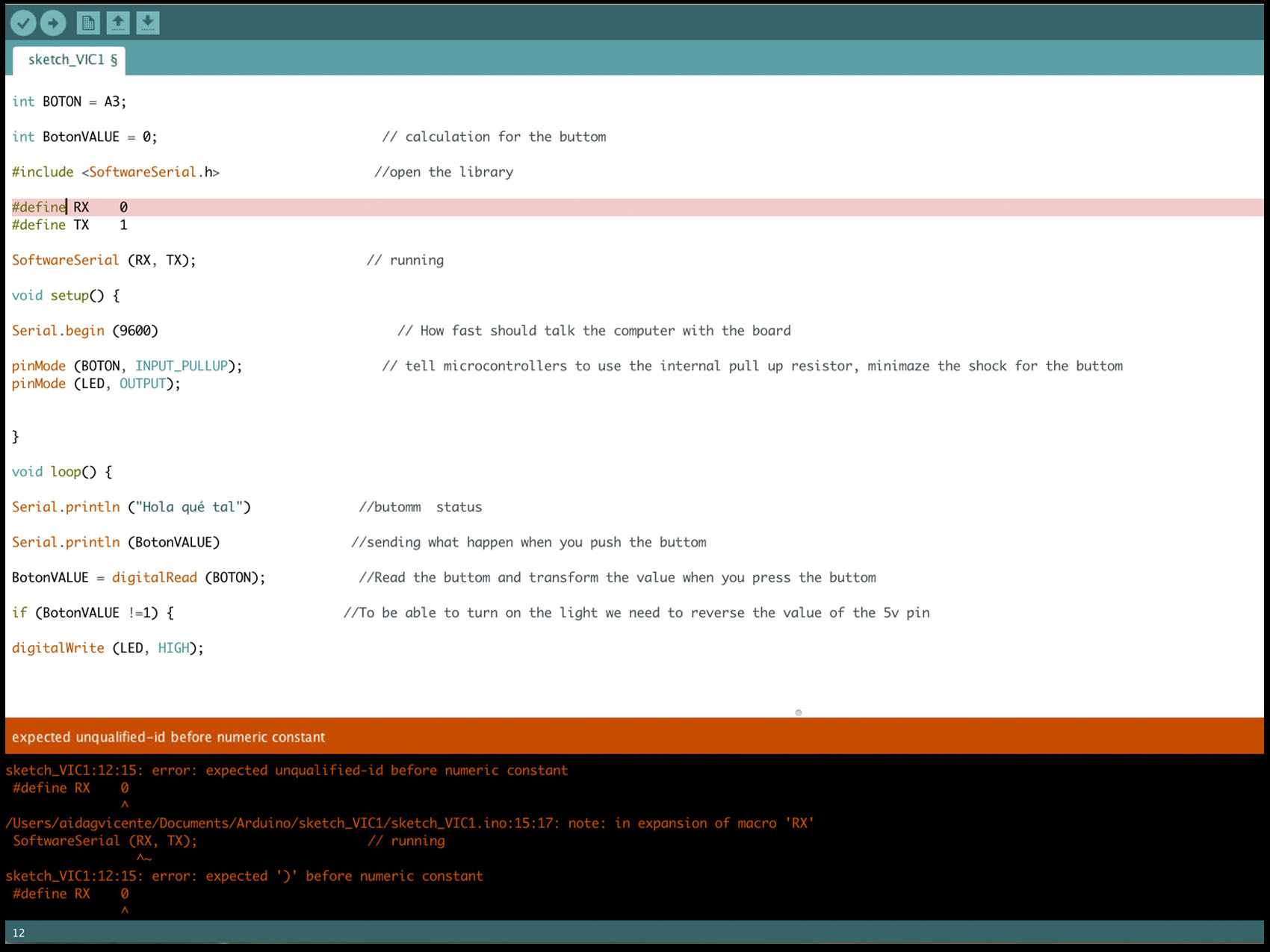
When you are programming your own board, connect ISP to the computer and ISP to the board. Set the board through tools: programming, port, clock because change between Arduino and the microcontroller used.
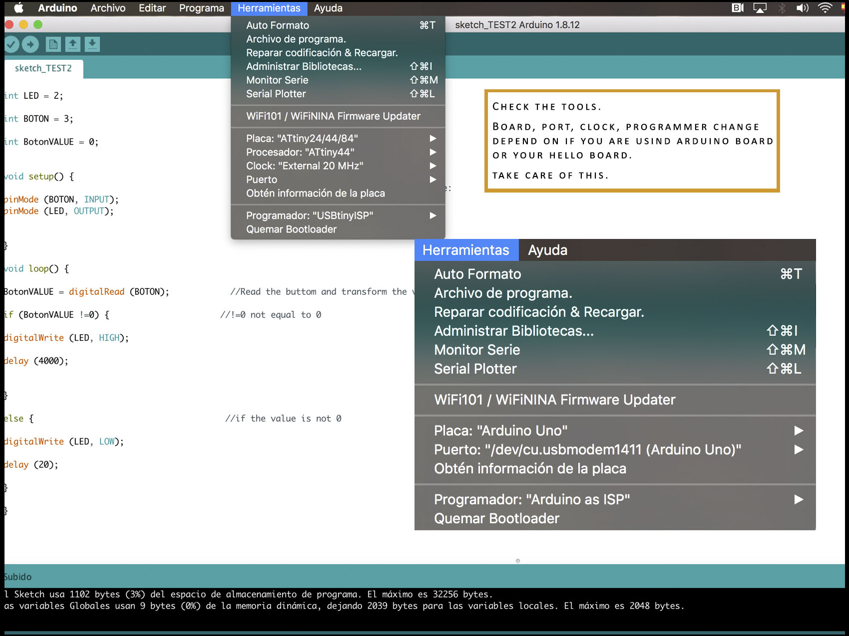
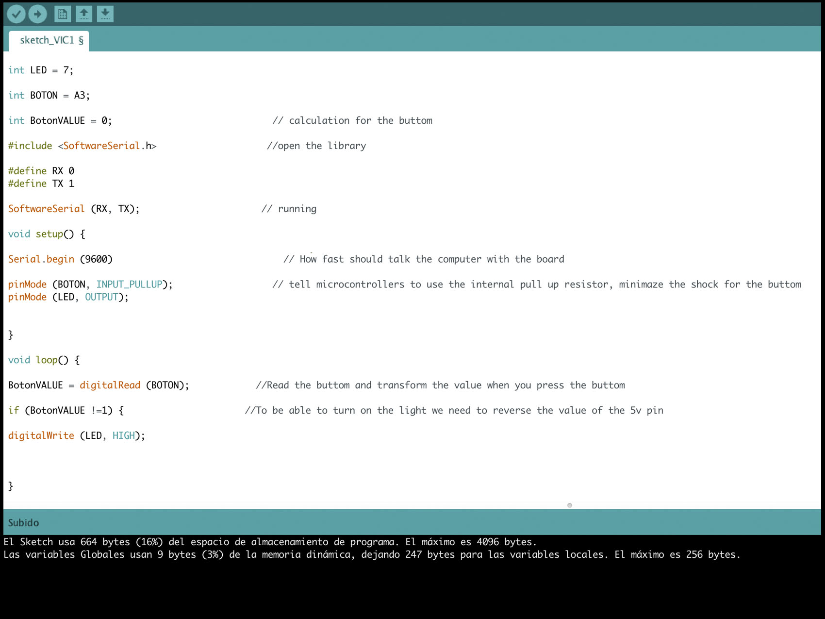
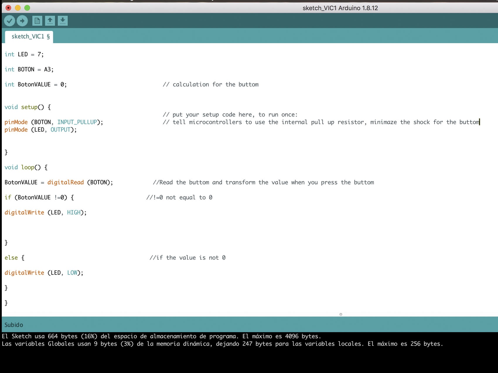
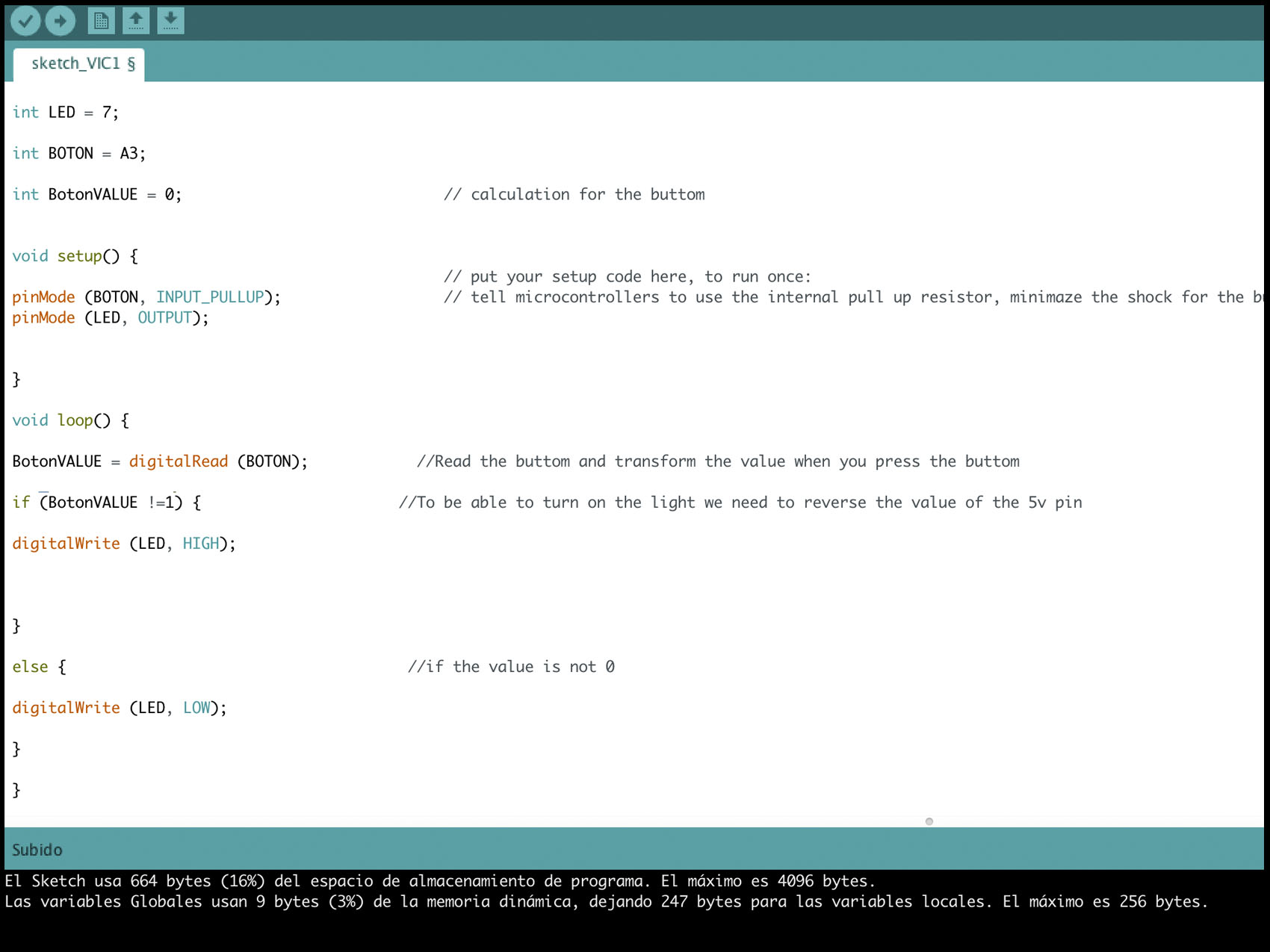
Inside the pictures you can read the notes about what each code is doing and also what I asking to the board to do and when.
Test 1:
Test 2:
Test 3:
First, I tried with Arduino kit:
And after with the same board ofweek 6 so, the elements on it are:
- 1x ATTINY44D
- 1x 6 pins FTDI
- 1x external clock 20MHz
- 1x red LED
- 1x 1uF capacitor
- 1x 2x3 pin header
- 2x 1kΩ resistor
- 1x button
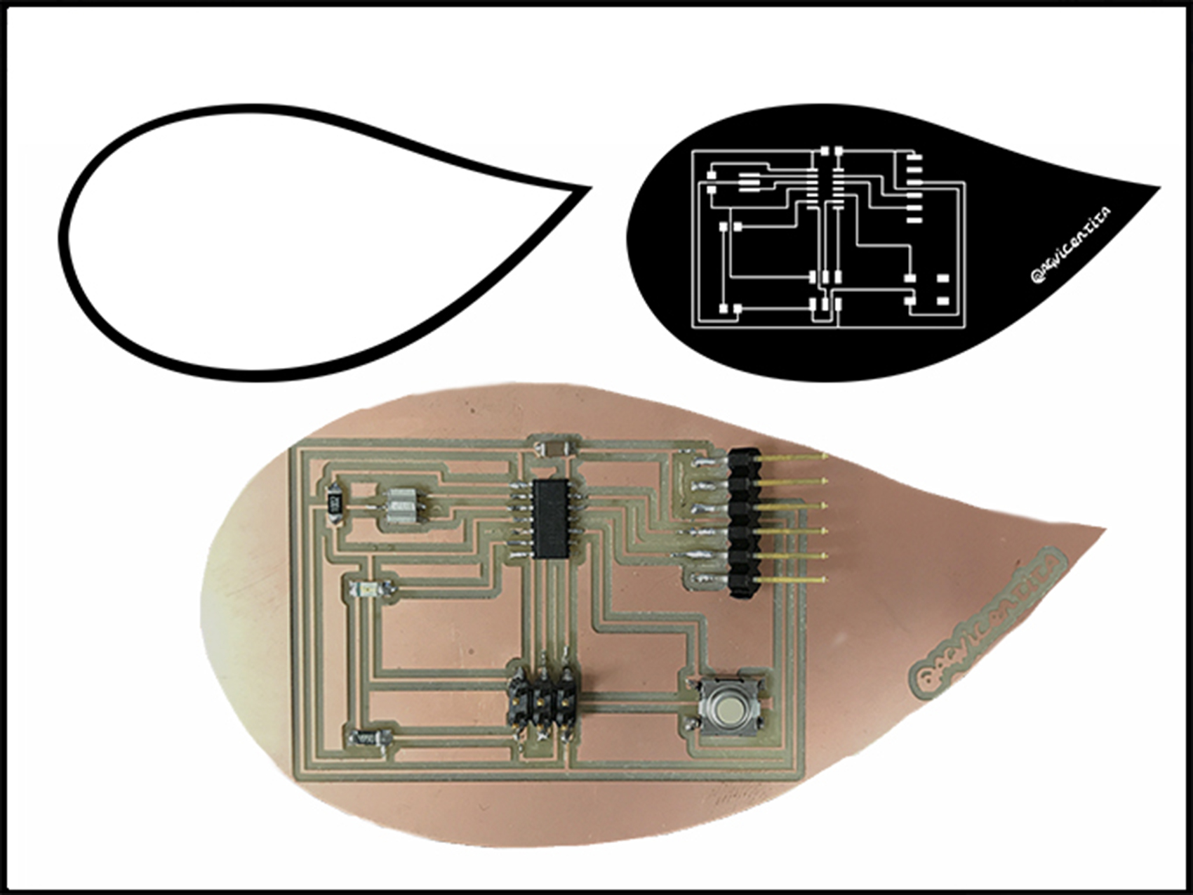
The next two pictures are the schematics and the traces of my hello board where I use ATTINY44D. On them, you can see the different connections and the functionality of each pin. The communications with the FTDI come from PA1 (RX) and PA0 (TX). The button is connected on PA3, the LED to PA7 the external clock to PB1(9 in Arduino), and PB0(10 in Arduino), and the 2x3 header has PA6, PB3(11 in Arduino), PA4 and PA5. The hello board only needs pins for what is built.
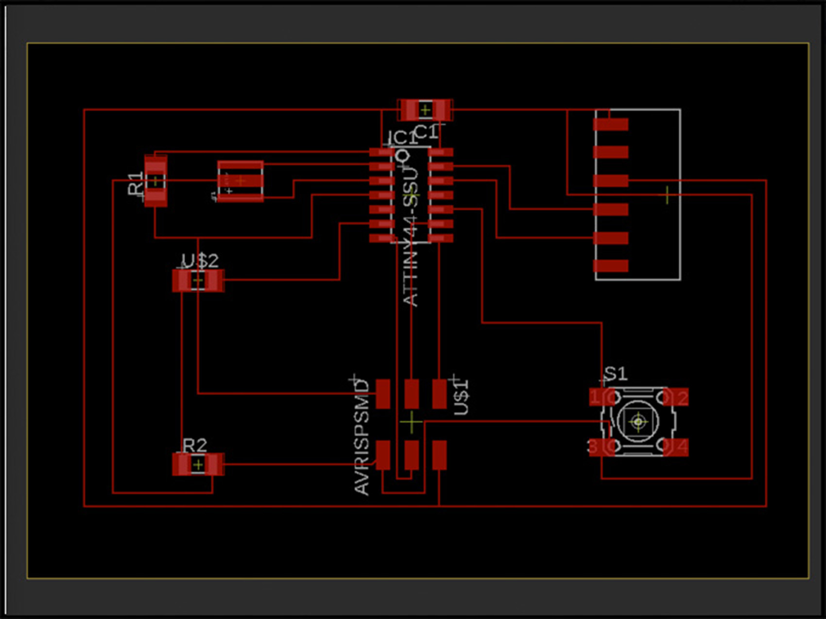
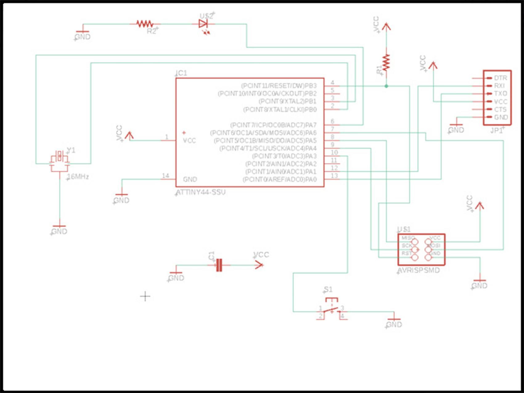
The las video shows how the hello board responds with this code.
Remember that if you are using MAC, it can be a possibility that you do not find the port. For that you need to run a bridge program in your computer and reset it You can read and watch a video about it on
Files
Arduinos scketches
Board cut lines
Board traces
Documentation
Arduino tutorial, variable.
Arduino tutorial, sketch.
Spence Konde
Started with ATTINY
ATTINY Family
ATTINY44 Datasheet