
Week 6
Electronic design
Keep going with electronic. We already have the ISP and now we need the board to program.
I meet a new program this week, also relative of Autodesk family, EAGLE. There I found the library of all the elements that I need to build a board. In this case, the board is ASTINY44D.
Once you find all the elements on the library, you set them in and you start to draw the board. In this case, the board elements are:
- 1x ATTINY44D
- 1x 6 pins FTDI
- 1x external clock 20MHz
- 1x red LED
- 1x 1uF capacitor
- 1x 2x3 pin header
- 2x 1kΩ resistor
- 1x button
However, this just begin, because after drawing it, you will need to draw the connections again.
One thing to take care of if the thicker of the line. I could not change it after, so I had to do it one by one on the traces draw.
Indeed, not forget to add to the setting de fab academy default.
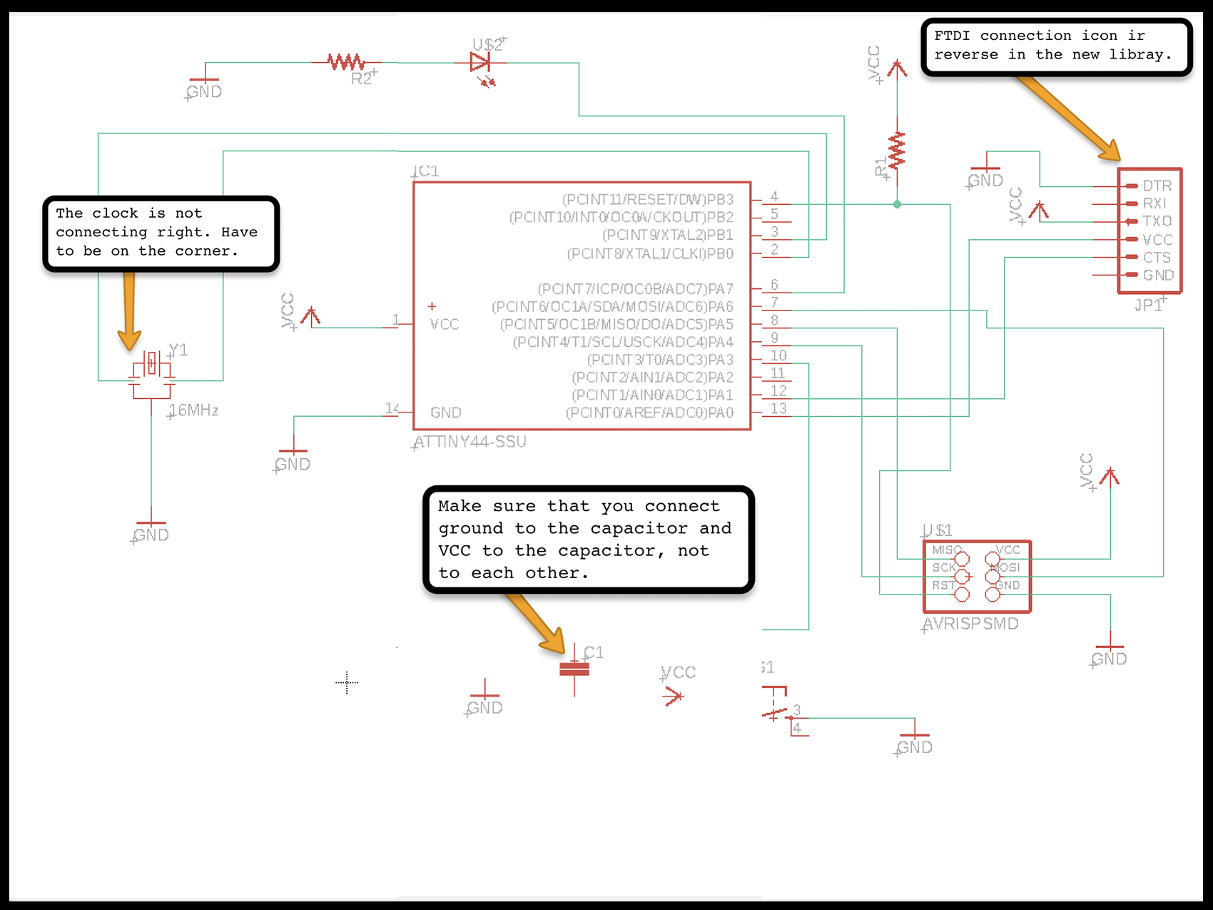
When you finished drawing you need to reorganize again but now you will draw exactly what are you going to print on the board. Then, it can be possible to change the form of the board.
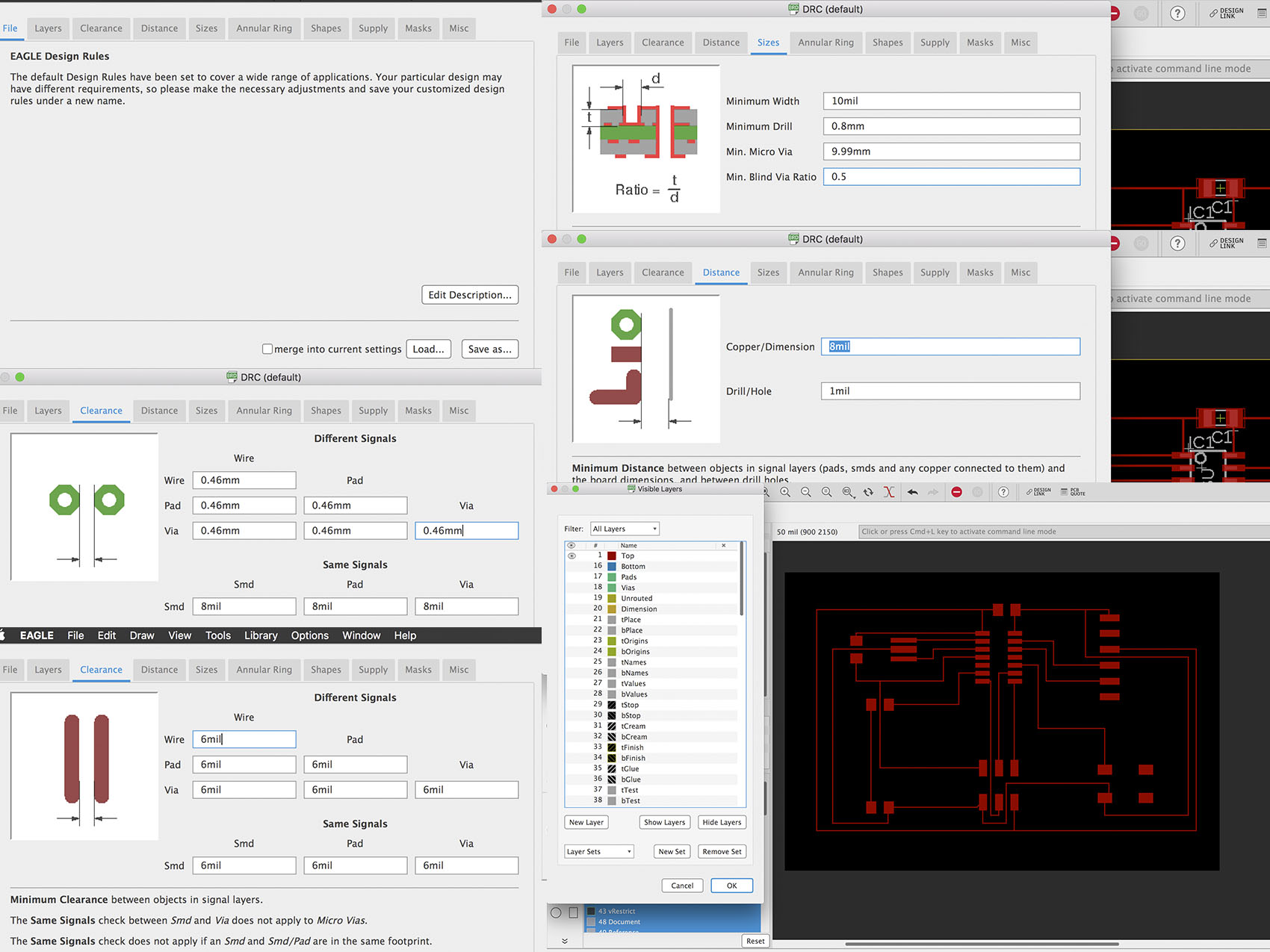
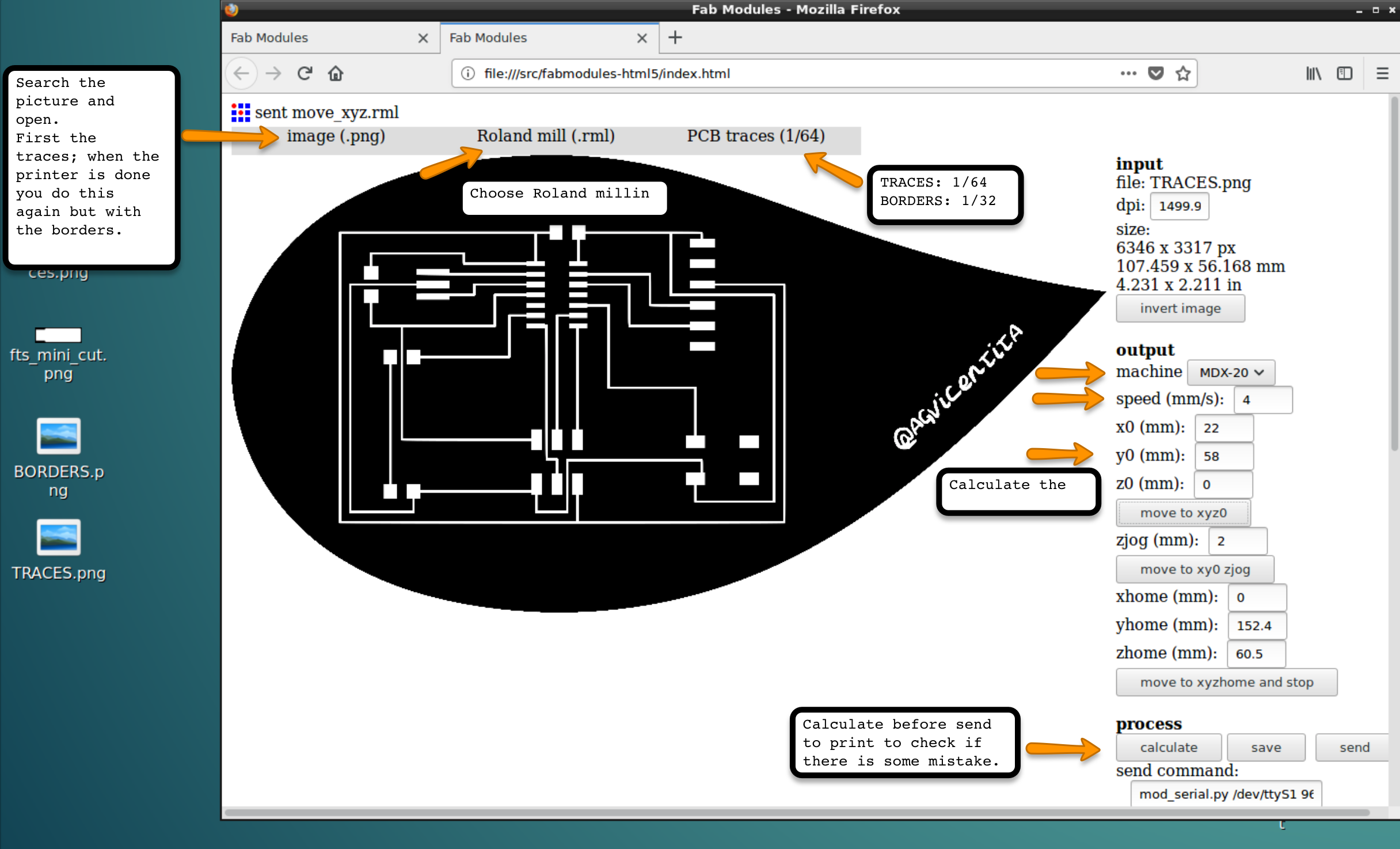
I wanted to be a little bit creative, so I change the form of the board for the head of a character that draw a lot and you meet in the week 3 on the vinyl assignment. So, I used Inkscape to draw the borders and prepare the board for the machine.

The printer process is the same than it was with the ISP.
- Clean the machine of dust or previous prints.
- Paste the material of the board.
- Calculate the traces.
- Calculate the cuts.
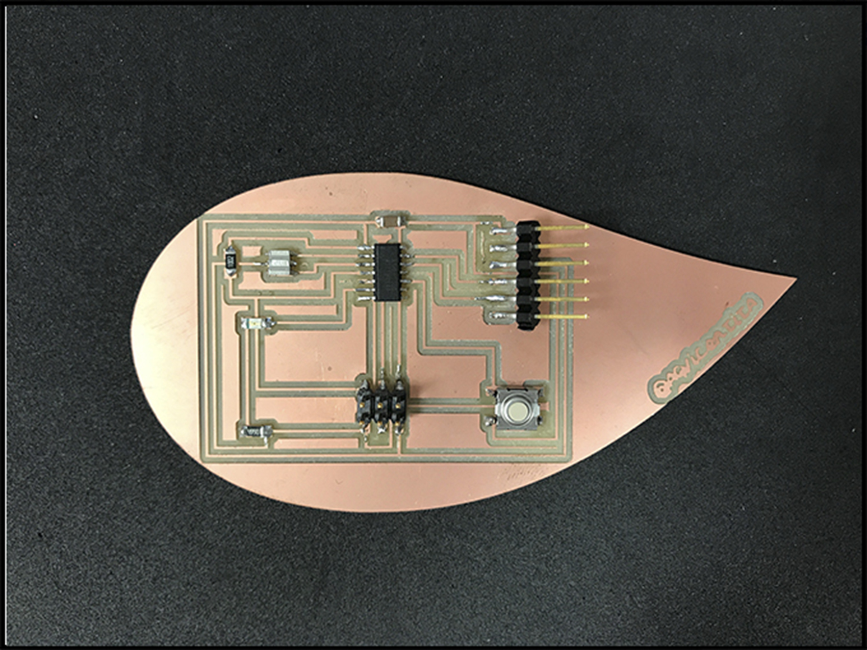
After weld all the elements to the board. It is time to program qith Arduino.
 So, I took my programmer (That I built on week 4) I connected the program cable from the board to the programmer, so they can talk to each other. You need a FTDI Cable to connect the board to the computer, and do not forget to connect the programmer using a cable, NOT DIRECTLY TO THE COMPUTER.
Even if you can see on the video that the programmer and the board were talking to each other. I have a problem with my computer.Before to reach this point, you open Arduino and adjust it to your task. When you finish, you burn the board just one time. And, now, you are ready to program. For this assignment I just sent the information to make the LED blink.
I am using MAC to program and I got a problem with the port, because MAC was not recognizing the port so, to fix it I had to:
- Download and set the drivers called CH341SER_MAC.
- Open terminal and copy this: sudo nvram boot-args="kext-dev-mode=1"
- Keep the folder on the computer. NOT DELETE IT
You can see more in this video: ARDUINO PORT MAC PROBLEMS
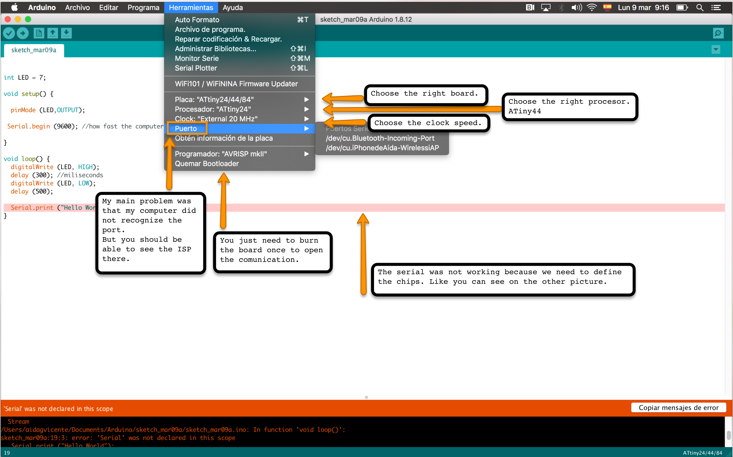
Fixed the problem, I could program.
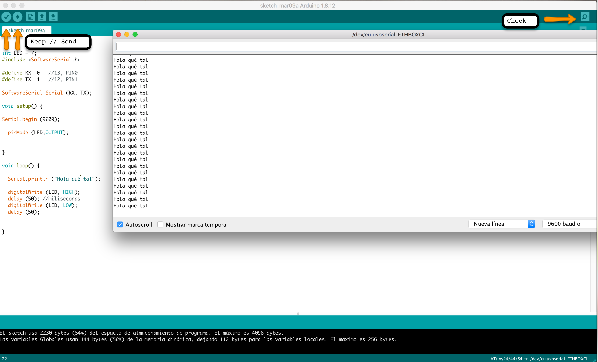
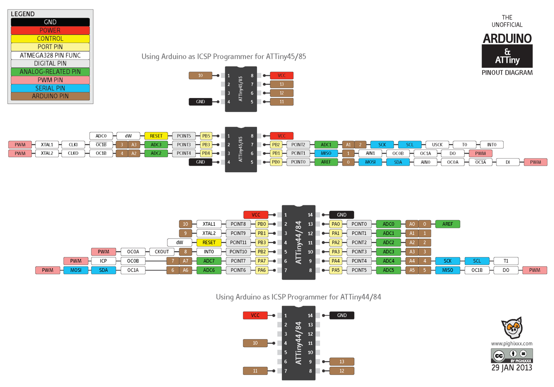
To know how Arduino has names the chips to not make a mistake programming, you can follow this:
The group assignment consisted on check the board with the multimeter/volmeter. With this tool we will be able to see the voltage that run through the traces and check if everything is working and connected like supposed to be.
The video shows that the 5 voltage are running from ground to VCC but when we checked next to the led the voltage goes down. That happens because of the resistor. Another curiosity is when the buttons is pressed the led turn off and the voltage goes from 2v to 0.5v.
Files
Eagle files
"Hola qué tal" Arduino sketch
Board cut lines
Board traces