Poster Presentation
In this section the information needed to work on the project is gathered from various published project and other resources as well. Based on my research, I found multiple resource that helped me to build my device. Below shown links and description of project related to my final project:
1- IOT Temperature data collector: Device consists of ESP8266 NodeMCU and connected to Google sheet where all data from the Temp sensor is recorded.
2- IOT attendance tracker :Device consists of ESP8266 NodeMCU, RFID reader and connected to Google sheet where all data of the attendance of the lab members is recorded.
3- Location Based Enquiry Tracking System: Device consists of ESP8266 NodeMCU, RFID reader and connected to Google sheet where all data of the books in a library are tracked
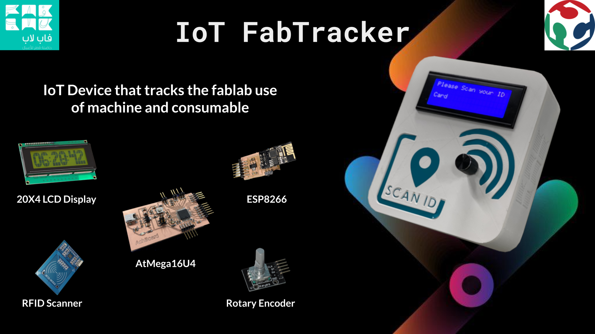
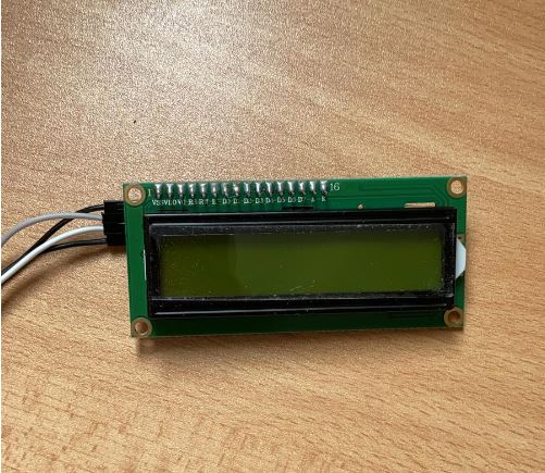
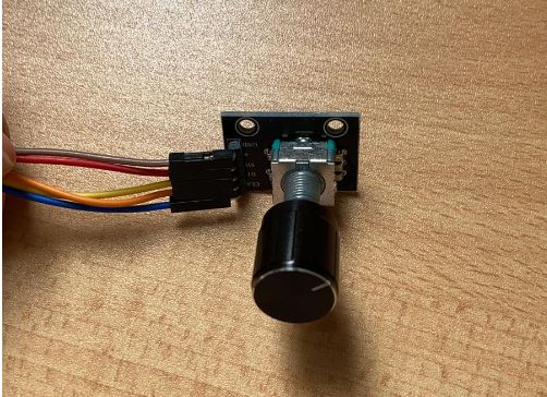
In this section, a detailed description about the preliminary composition of each component in the designed device is presented. Furthermore, in this part the methodology of prototyping the device will be explained. The IoT smart device consists of a different electronics list including Wifi-enabled NodeMCU board, Arduino Nano Board, RFID reader, LCD screen, speaker, 5V USB power cable and Solderable breadboard. as shown in the figure below.
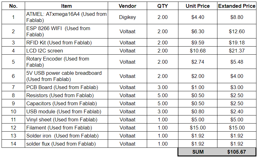
The initial prototype is estimated to have following items:
The below chart, presents the flow of experience that the user will be going thought while using the IOT FabTracker. It was presented to programming flow and help the user undertand how to use the device.
3D Design Description
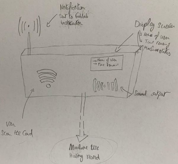
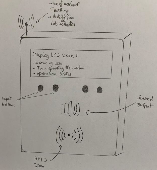
This section will be covering the preliminary 2D and 3D design proposed for the final project prototype. Different iterations will be performed to be able to determine the suitable design for the project needs. Below shown the procedure to create the final project model using Solidworks software.
The design consist of two major part:
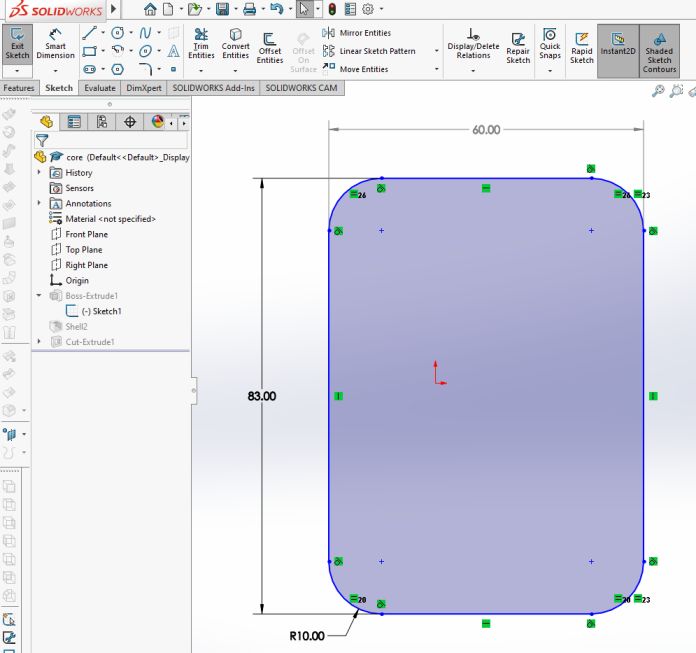
The Core/Container :
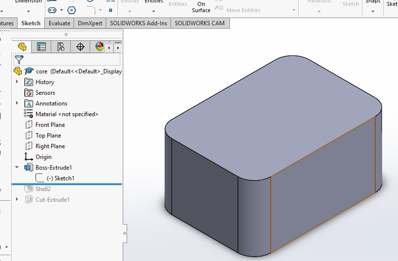
The design started by drawing the sketch of the core. The smart dimension feature was used to specify the measurement for the core. Additionally, the sketch fillet feature was used to remove the sharp edges of the design, as shown below.
Since the 2D sketch was made, the 3D model is ready to be generated. Extrude feature was used to generate the 3D model as shown below.
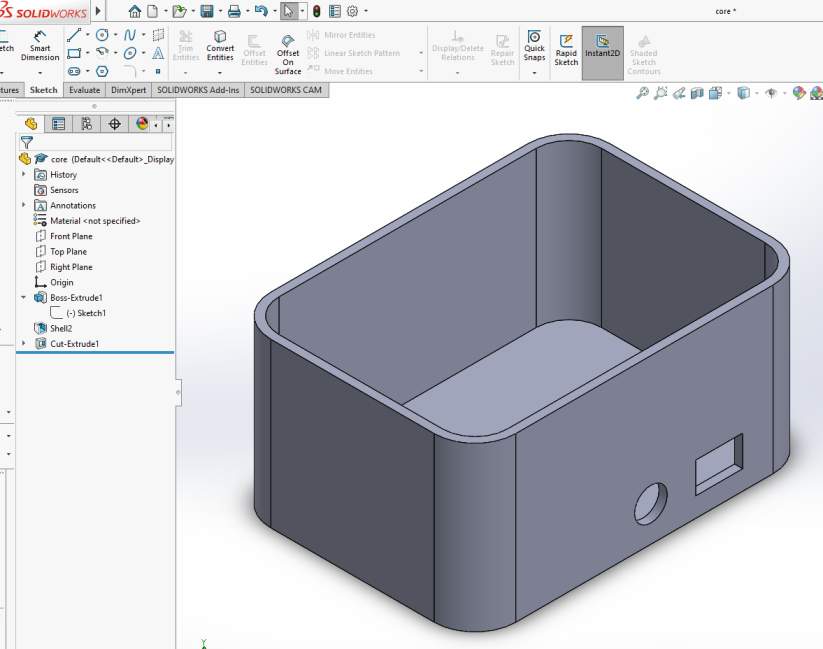
The part presented above is considered as a solid body, Shell feature was used to have a top opening on the body with a thickness wall of 2mm. Additionally,the Extrude cut feature was used to identify the openings for the electronic wires to be added later on the design as shown below.
2. The Cover :
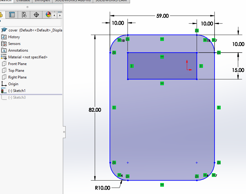
Second step is to develop the cover of the prototype. 2D sketch was made, taken in consideration of the core dimensions. The sketch consists of one opening for the LED display screen to be placed, as well as the sign of the RFID, where users will scan the membership card. Sketch is shown below.
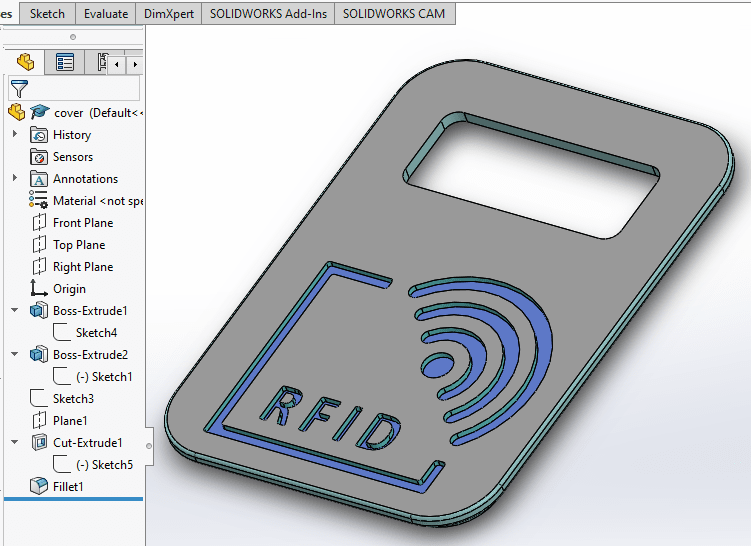
Since the 2D sketch was made,the 3D model is ready to be generated. Extrude feature was used to generate the 3D model as shown below.
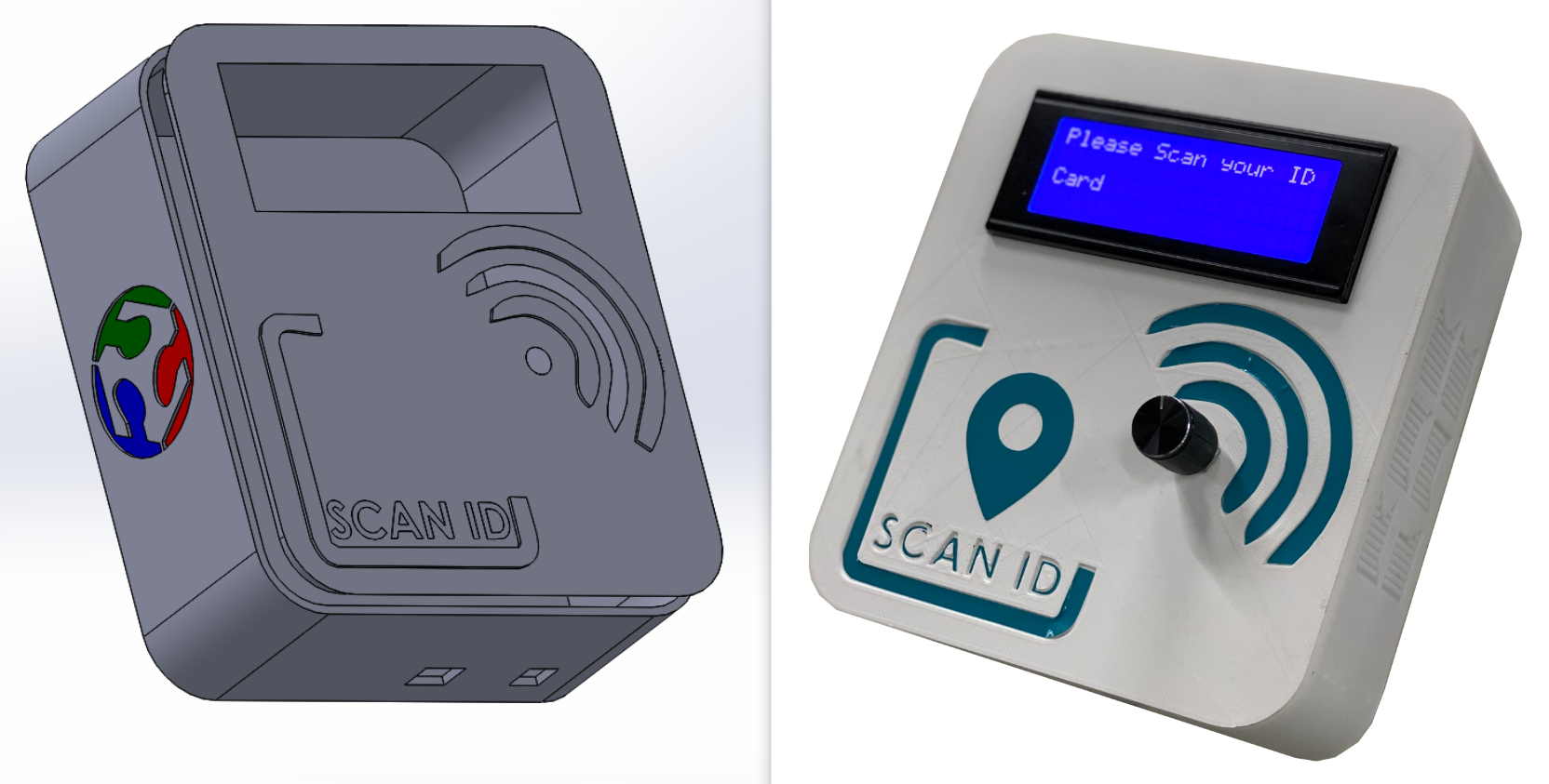
3. The Assembly :
The final step was to assemble both parts. To perform this step a new Assembly file was created and the two parts were added. Mates feature was used to restrict the part degrees of freedom. Assembled parts shown below.
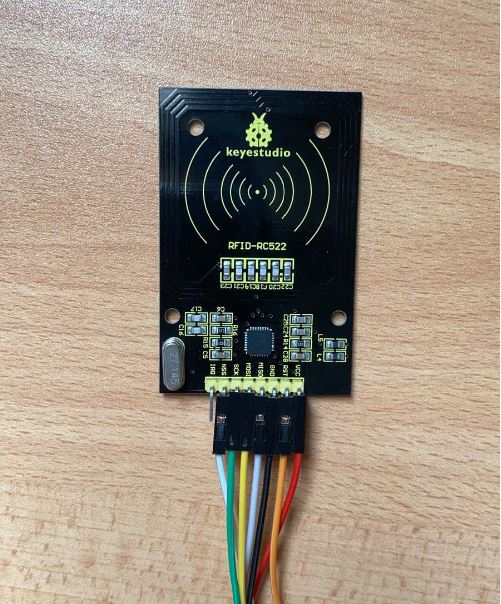
This section will cover details on how each electronic component work and how it was tested. The good thing that the embedded programming part of my project was covered in the assignment part. So for the Atmel programming and network Wifi communication I have linked my work directly to the assignment pages were all the detailed steps were explained and the electronics were tested.
- Embedded Programming
- Network and Communication