- Individual assignment
Introduction
For this week assignment I decided to use ESP8288 Wifi module since it will be used in my final project. The ESP8266 WiFi Module is a self contained system-on-a-chip (SOC) with integrated TCP/IP protocol stack that can give any microcontroller access to your WiFi network. The ESP8266 is capable of either hosting an application or offloading all Wi-Fi networking functions from another application processor. Each ESP8266 module comes pre-programmed with an AT command set firmware, meaning, you can simply hook this up to my Atxmega board.
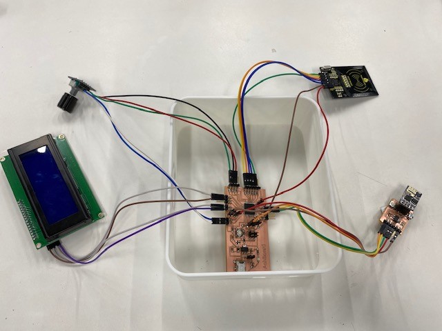
To make my WiFi board I needed this components:
1. ESP8266
2. LM1117 the 3.3V voltage regular
3. 10K Resistor
4. 10uF Capacitor
5. 1uF Capacitor
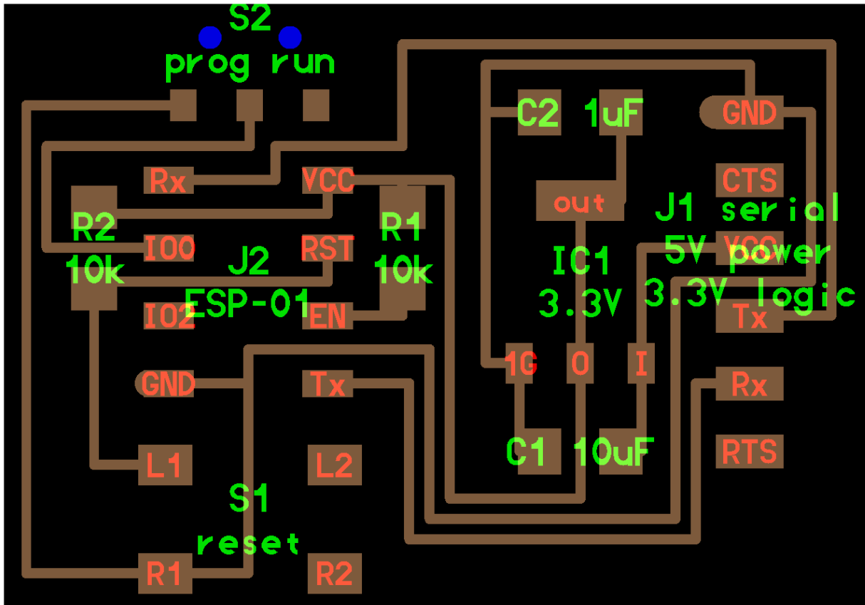
Board Design
The board design was downloaded directly from the 2020 course resources

Board Milling & Soldering
- Once the design was ready I used the roland machine to mill the board and start the soldering. I prepared all the componants I needed. The milling process started by creating the G.code and uploading the file to the milling machine, as shown below
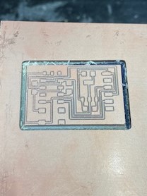
- The milling process started by creating the G.code and uploading the file to the milling machine
Soldering
- Soldering process was so much fun and challenging. My soldering techniques are getting improved more and more, however I had to repeat my board multiple times, since I get short circuits alot. The 44 pin microcontroller was very challenging to solder and my colleagues in the lab helped my alot by showing me new techniques of soldering.
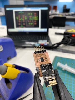
I used the electronic magnifier to spot the small short circuits location as shown blow
- below shown the final result of soldering process
Board Programming
- Once the board was ready I started the board programming. This process was challenging since I faced difficulties in programming the ESP module.
1- First step was to flash the ESP module then upload the AT commend frimware. To do that I had to download the ESP flasher tool. Then I have connected my ESP to the computer using the FTDI Cable available in the lab. The FTDI cable connections are
- 3.3V FTDI cable connects to the GND and VCC of the board
- FTDI cable TX ESP8266 board TX
- FTDI cable RX ESP8266 board RX
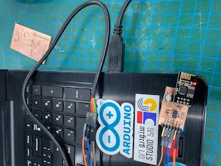
- Now the ESP Module is ready to be used for my final project
API Connection to Google sheets
- A very important task that I had in my final project was to send data from my device to google sheets to be saved in the cloud and the lab instructor have live access to the information (refer to final project page for more information about the final project).
to establish this connection I had to use the following:
- Google sheets/Script
- Arduino IDE
- API Pushingbox
1- Create and Deploy the google sheet
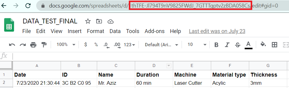
First step, I had to create a google sheet. This will be the sheet where my data will sent to. At this point I had to copy and save your spreadsheets URL key. This key is listed in the URL between the “/d/ ” and the “/edit ” of your new spreadsheet (see blue circle).
then I created Google App Script (similar to JavaScript) which will process my data and populate my spreadsheet correctly. To insert my Google App Script we first navigate from our spreadsheet to the Script Editor: Tools →Script Editor
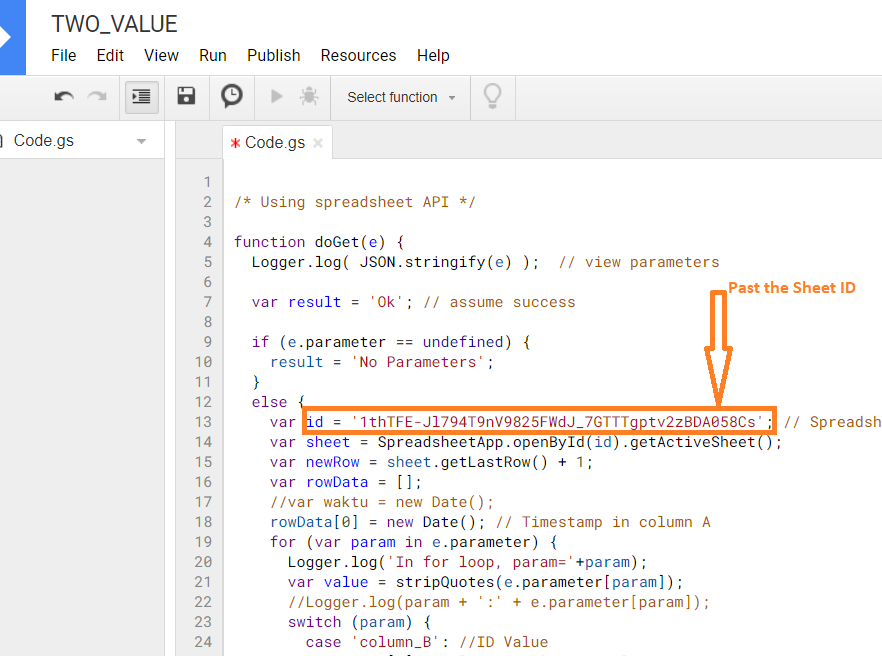
Once the Google script sheet is open, I modified the Google Script in to the editor, to brief you about my Google Script File , its made to give me the chance to push variables to the google sheet. you can find more information the script comments.
Copy and paste the previously saved spreadsheet URL key into the correct line in the Google Script code (between the quotes) where it says: "var id = ' '; // Spreadsheet ID". Then Save the script: File→Save All. and finall Deploy as a web App: Publish-→ Deploy as web App…
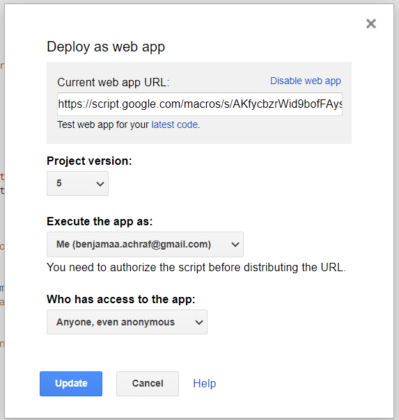
The final Step for setting up our Google sheet will involve configuring the Web deployment parameters. It is important you set all these fields correctly. If you don't set all four fields exactly your spreadsheet won't work properly.
- Field 1) Copy and Save the “Current web app URL:“ which has just been generated, we will need this later when we configure our API in PushingBox.
- Field 2) Save a project version as “new” on each iteration, it’s important to note that if you don’t make a new project version for each script revision you make (if you decide to make any revisions), your script revisions won't be updated on the web. This is counter-intuitive, and easy to neglect, but this is currently how Google has this system configured.
- Field 3) “Execute the app as: “ set this to “(your gmail here) ”.
- Field 4) “Who has access to the app: “ set this to "anyone, even anonymous."
2- Configuring PushingBox
- Serves as as simple, free, and easy API middleman in allowing our DHT data to be palatable to Google Sheets. The need for using the PushingBox API intermediary is to turn our HTTP transmitted data into Google compliant HTTPS encrypted data. We could attempt to make a non-trivial encryption algorithm to satisfy the standard requirement but using PushingBox is easier, and we are given up to 1,000 requests a day for free
1- Create a PushingBox account using your Gmail.
2- At the top click on “My Services”
3- While now in “My Services” go to the “Add a service” box and click on “Add a service”.
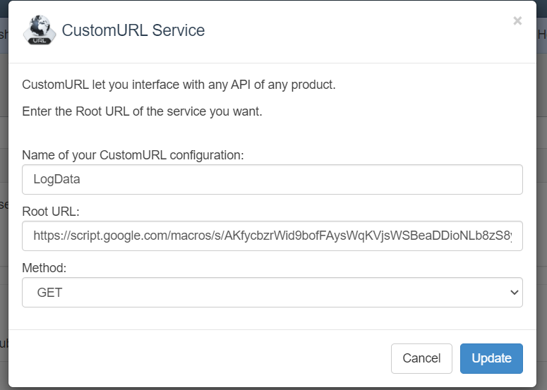
4- The service you will want to create is the last item on the list of services and is called: ”CustomURL, Set your own service !". Now select this CustomUrl service.
5- A box will open up and ask for three items. Fill them out.
3- Arduino Programming
At this stage the API was set and ready to send data directly from the ESP8266 to Google via Pushingbox over WiFi. For the arduino sketch it was important to add the the 3 following fields:A) WiFi name
B) WiFi Password
C) Pushing box Device ID (devid)
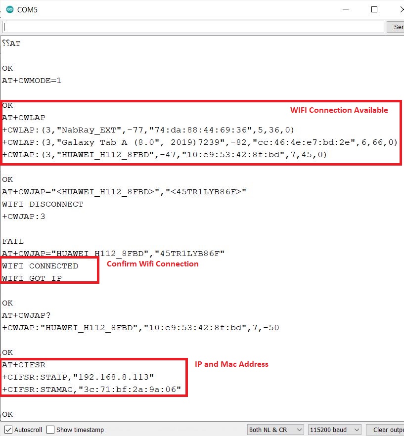
That’s it, your done! If everything was completed correctly your output will look something like the picture below:
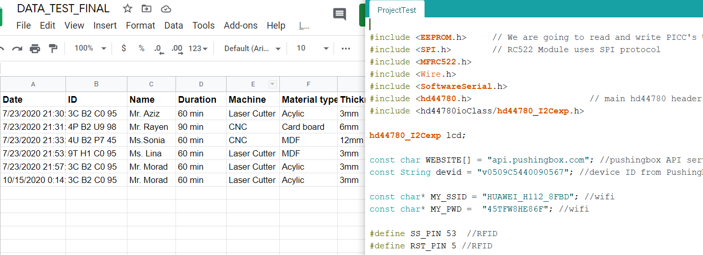
-->Arduino Code