Computer Controlled Cutting 📋
🕘 Date / Time:
Hello there mates, hope everything is alright. ^^ This is our third week of Fab Academy and things are getting much more exciting!
We had a group assignment and Individual assignment, both were fun. ^^
A) Group Assignment:
The Assignment was documented on the lab page.
My Reflections:
Saturday afternoon we started discussing how we’d approach the group assignment. We reviewed the requirements, divided them into tasks and assigned a task to each one of us.
My tasks:
1- First task was to search for the rate characteristic.
Result: we found out that rate is not an independent variable to be adjusted or controlled using the laser cutter we have in our lab. Neither the software “RD Works” nor the settings of the machine itself included that rate parameter or anything that was measured in Hz or Pulse per second.
I do guess though that the rate Neil illustrated can be manipulated by controlling speed and resolution simultaneously.
Speed (mm/sec) x Resolution (Pulse/mm) = Rate (Pulse/sec).
2- Second task was to collect data during the characterization tests and do the initial documentation. This task was quite handy as it helped me learn how to operate a laser cutter, to do characterization tests as well as to detect & troubleshoot abnormalities in test results if present.
B) Individual Assignment:
a)The laser cut press-fit construction kit:
The story started with a dilemma:
Where to start? How to approach the task?
Shall I have a specific outcome in mind design all its parts then laser cut them?
Or shall I design a couple of key units, laser cut multiples of them then give myself a space to get creative?
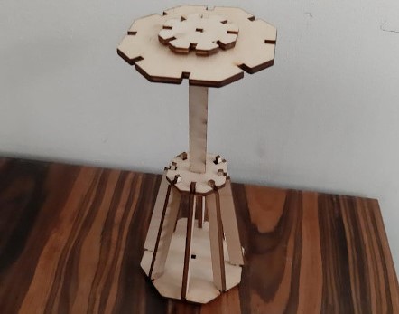
I gave it a lot of thought and since I couldn’t come up with a specific outcome that satisfied me, I went through with the “Get Creative” option. :D
Key units:
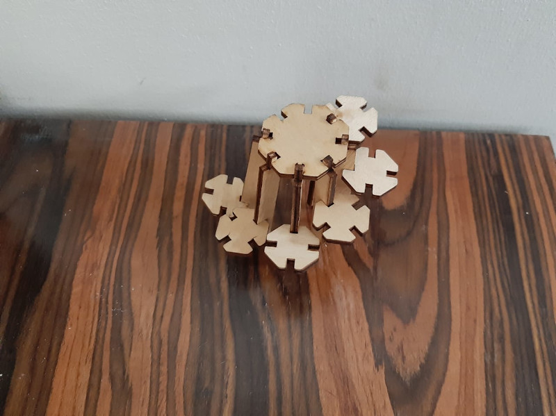
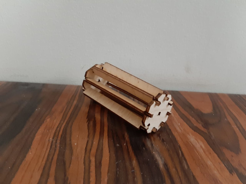
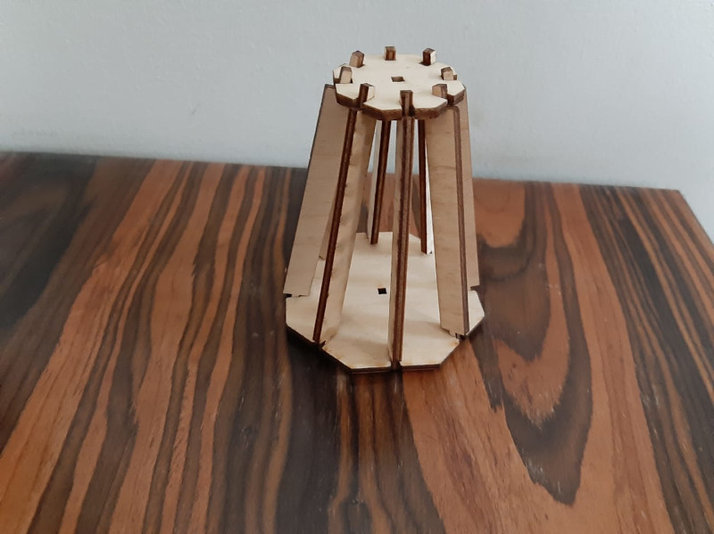
“The Mighty Octagon” was chosen to be my main unit. *I really do like octagons :D*. As well as some rectangular connecting elements.
Parametric Design:
I tried to use Free Cad but I reached a dead end, as I was neither familiar with its interface nor its commands and I found it pretty dull actually.
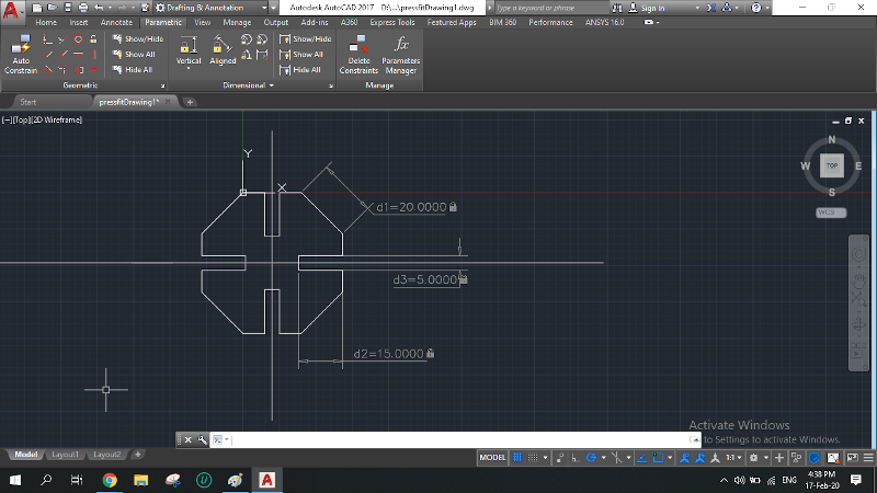
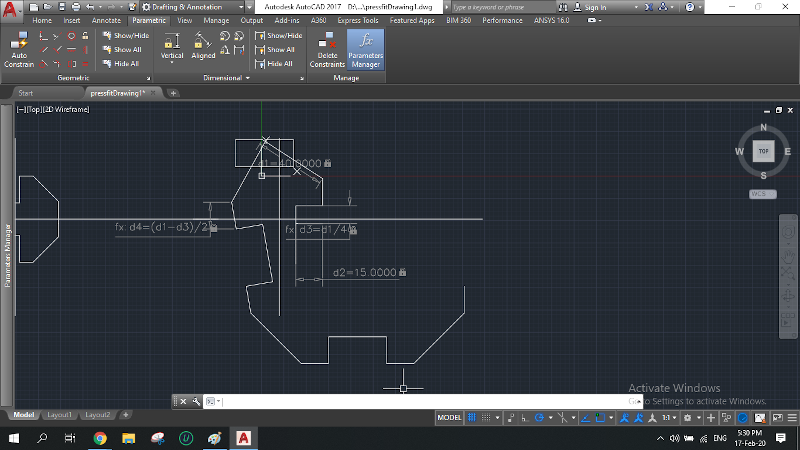
Tried to get back to my beloved Auto Cad but its parametric design commands and constrains were not familiar to me either. They seemed highly sophisticated and I tried to get them to work but unfortunately I didn’t have the luxury of time _as usual_ to keep trying till I get them right (I hope I will master them; I know one day I will).
Finally, I was advised by my instructors to use Fusion 360. Brand new as it was but using it I was able to proceed through the task. Receiving help from “Khaled”. ^^
Here are some documentation steps along the way:
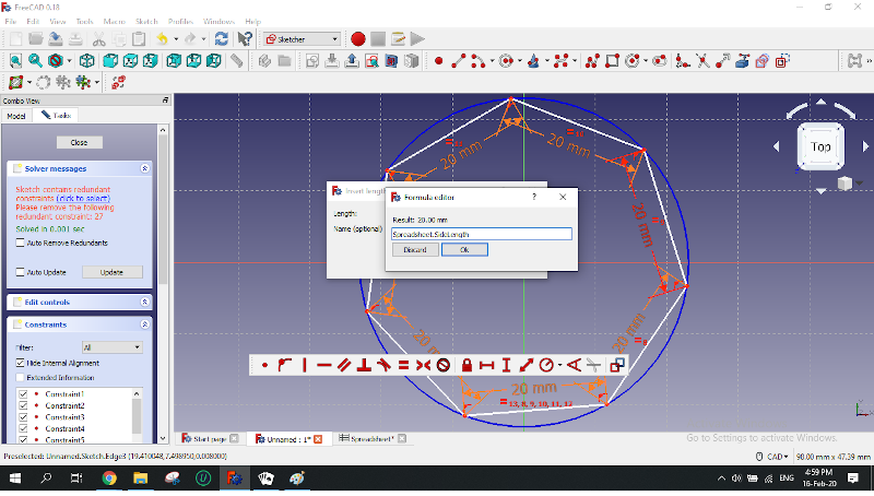
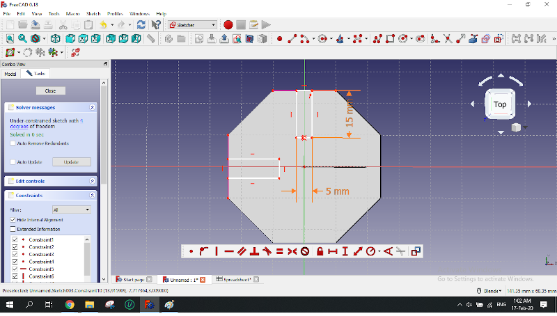
Free CAD trials:
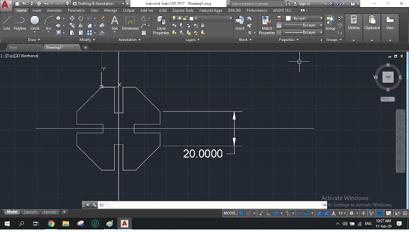
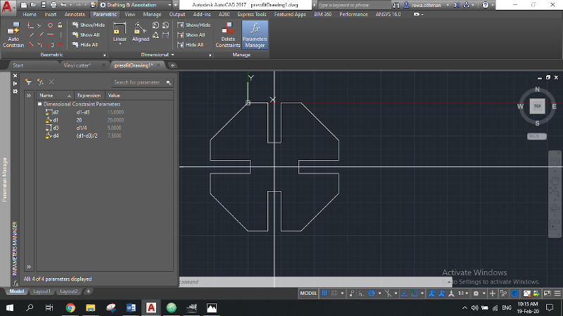
Auto CAD trials:
Fusion trials:
First trial
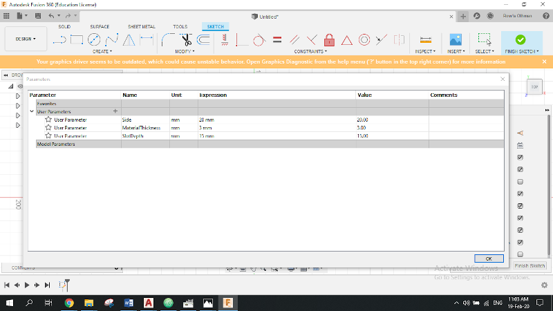
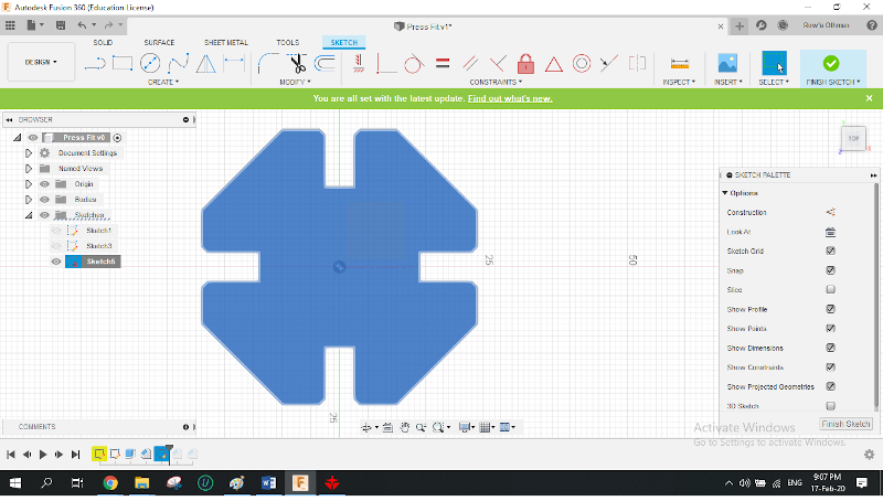
Initial Sketch of the Mighty Octagon using Fusion 360 for the first time.
1- I created a new sketch and chose the x-y plane.
1- Added the 3 parameters I needed.
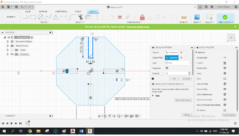
2- Drew my octagon from the origin point, assigned “Side” as the octagon side dimension.
3- Drew two axes of symmetry from the origin point, then I fixed them in order to constrain the octagon.
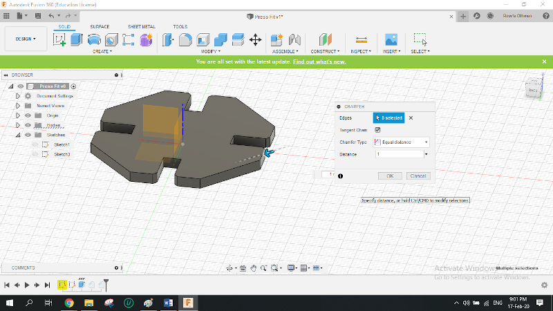
4- Drew the rectangular slot on one side, assigning parameters (thickness and depth) to its sides.
5- Created a pattern of 4 slots on 4 of the opposite sides of the octagon.
6- I followed a similar process with the connectors using the same commands. ^^
flexible connector trials. :D
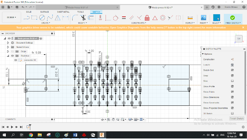
I alternated my key elements a slight bit along the way tried and failed numerous times, came up with all sorts of weird constructed sculptures :D, and below you will find some of my cool sculptures followed by my long list of failures. :D
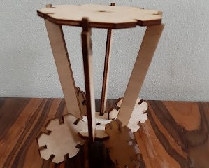
Cool sculptures:
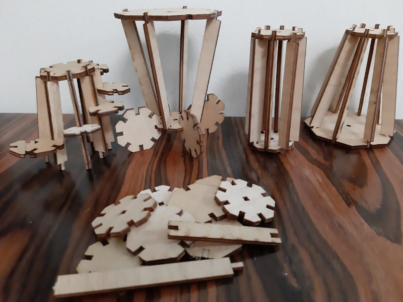
Failures:
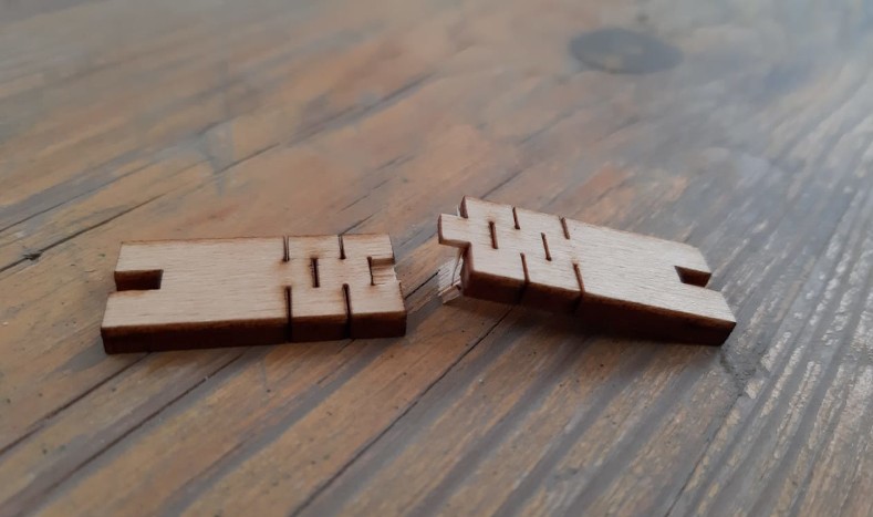
1- Material thickness parameter was set to 5 mm while the plywood I used was 3 mm thick.
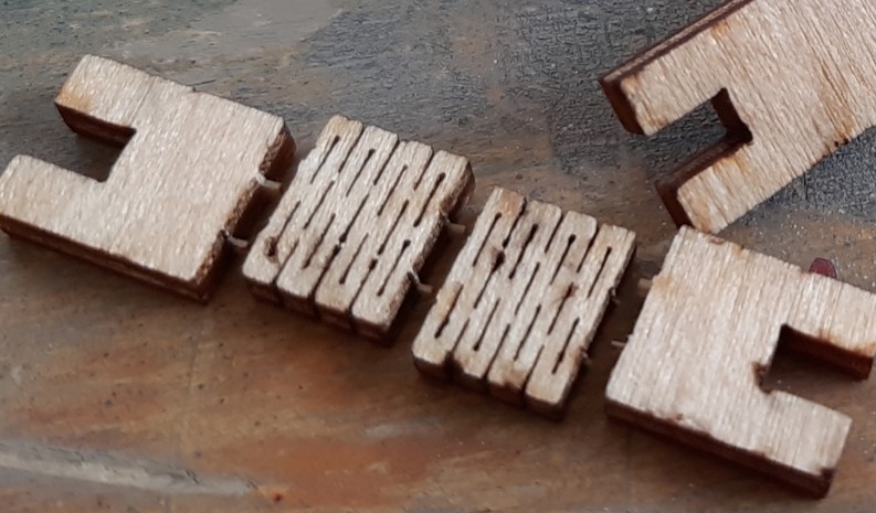
2- Second trial on the laser cutter was to 3 elements a connector, an octagon and a supposed flexible connector. (Thank Allah I cut only three specimen).
a) They fit together by interference as there was no clearance between them but the kerf and apparently it was not enough.
b) The so called flexible connector was not at all flexible :D and I was told I should have done some calculations to get the appropriate spacing between the cuts of the bending pattern. Did not find any calculation on the internet, so I tried to redesign the flexible connector. It failed for the second time.
3- I was told that there were some downloadable hinge files that can be imported to inkscape _another CAD software_, I downloaded and set it up hoping it was a bit similar to any CAD I’m familiar to, but unfortunately it wasn’t. And I didn’t have the time to learn it from scratch now that time is almost up. Failing to get the flexible right and having so little time to start with inkscape, I decided not to include flexible joints into my kit.
The vinyl cut sticker:
As for the vinyl cutter task:
It was nice and simple. ^^
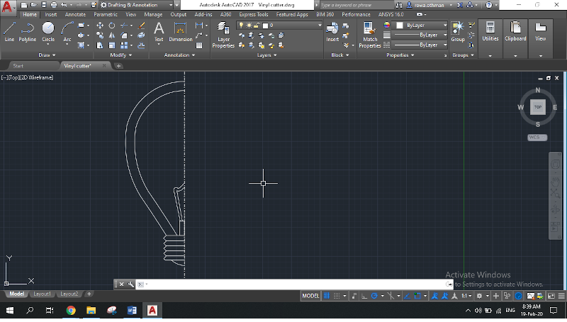
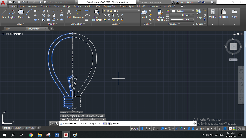
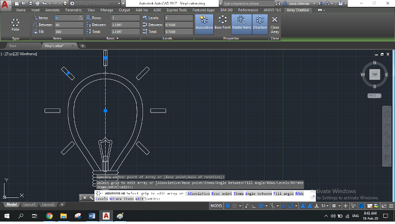
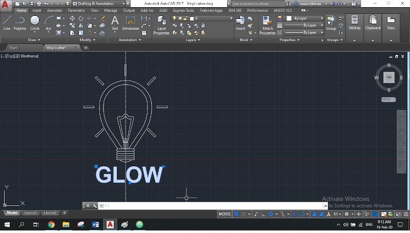
I used my beloved Auto CAD to draw a nice light bulb (I love light bulbs too) and the word “Glow”.
Auto CAD Design Steps:
Failures:
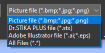
1- Turned out that only files with the extensions shown below can be imported to "Cut Studio" the vinyl cutter software. And unfortunately Auto CAD saves files only as dwg., .dxf, .pdf and other extensions that are unknown to me but neither suits cut Studio.
2- I tried exporting the file as a pdf then take a screenshot to get a png to import it to Cut Studio. The results were really bad as most of the traces were unidentifiable by the software. I was told that this was because the light bulb shape was not filled in black and that I could use "Gimp" the photo editor to fill it, but that was utterly inefficient as well.
3- I then tried saving as .dxf from Auto CAD and open it by the Laser cutter software "RD Works" to be able to save it as an .ai file but and for some reason there were parts missing from the design. This too didn't work out.
After all this unnecessary hassle, I had to do a change of plans.. I gave up on my Auto CAD design as the perpose of the task was just to cut something using the vinyl cutter.
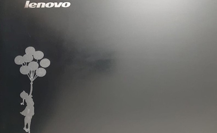
So, I downloaded a nice silhouette image from google as a .png and decided to cut it instead.

Vinyl Cutting Process:
1- Install updated Cut Studio and its driver on your laptop.
2- Acquire a suitable piece of vinyl.
3- Feed it to the machine and scan it to get its dimensions.
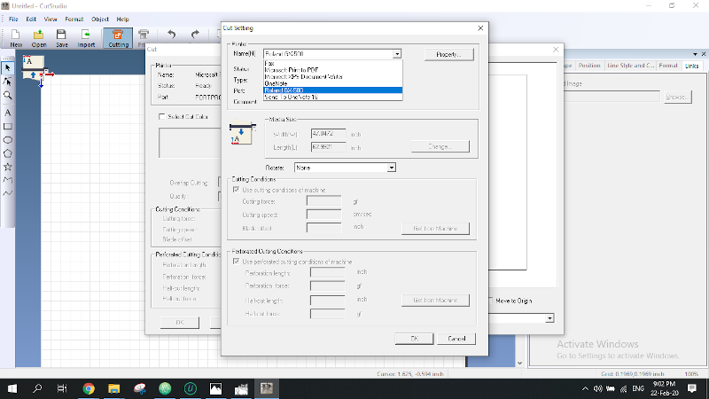
4- Click on "Cutting" icon, select the machine in your lab.
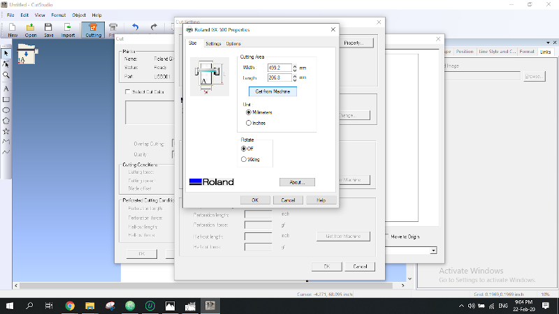
5- Click on "properties", then "Get from machine" to let the software recognize dimensions of the piece you're using.
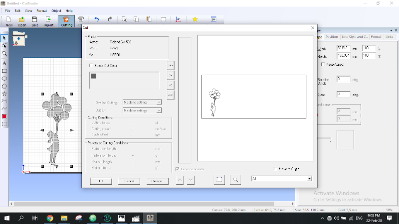
6- Import the image you want to cut and scale it to the size you prefer. (If you want the dimensions in mm instead of inches you can change that in File menu >> preferences).
7- When all is set and done click on "Cutting" icon then "ok". And watch the Vinyl do its magic. ^^
Cutting steps:
Failures:
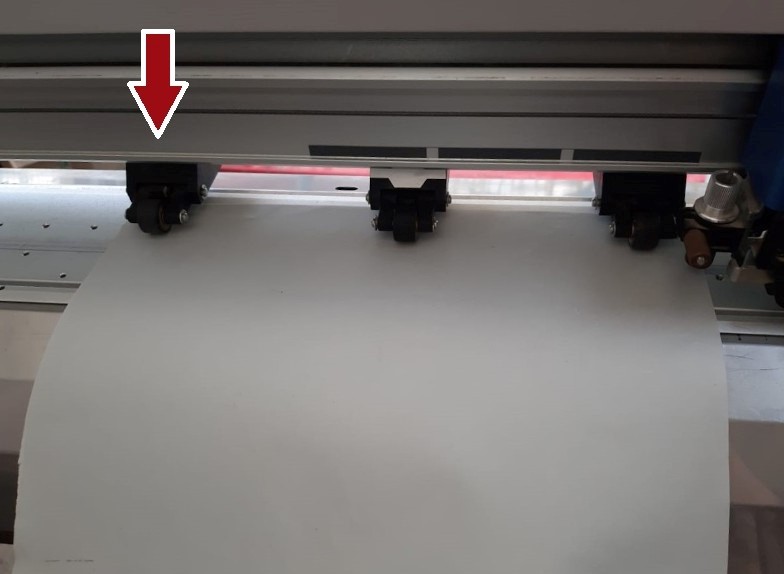
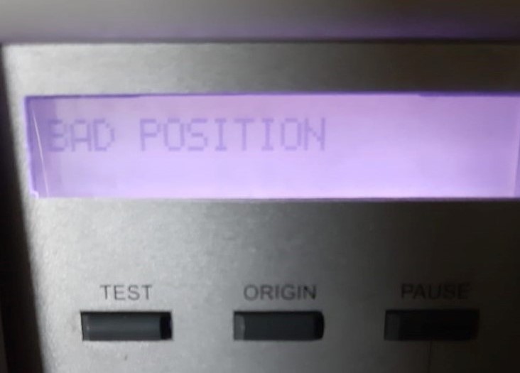
1- The machine's screen had this message: "Bad position". Turned out that I was misplacing the machine's pinch rollers. The
lateral pinch rollers have to be placed at the designated indicators marked in black.
Learning outcomes:
By the end of this week, I had learnt operating both laser cutter and vinyl cutter. They are really fun and each has its own tricks.
But the highlights were:
1- That I learnt I should always try to keep calm, keep working and everything is going to fall right into place.
2- I should work more on my time management.
Downloadables: 💾
Fusion Files:
1st octagon 4 slots.
2nd octagon 8 slots.
3rd octagon (larger).
60mm & 100mm Connectors.
AutoCAD File:
Light Bulb Design.
©️ Row'a M. M. Othman - Fab Academy 2020