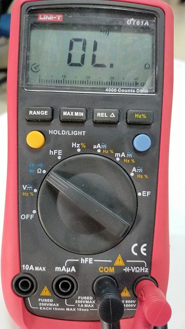
Digital Multimeter is a device which used for the Electronics and Electrical equipments measurements. It is most important and useful equipment for testing and Troubleshooting of electronic Circuits. We can check Connectivity, Resistances, inductance and voltage in the circuit using multimeter.
Connectivity Check
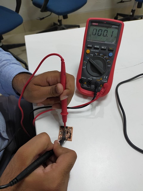
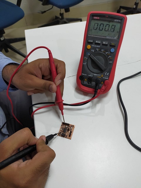
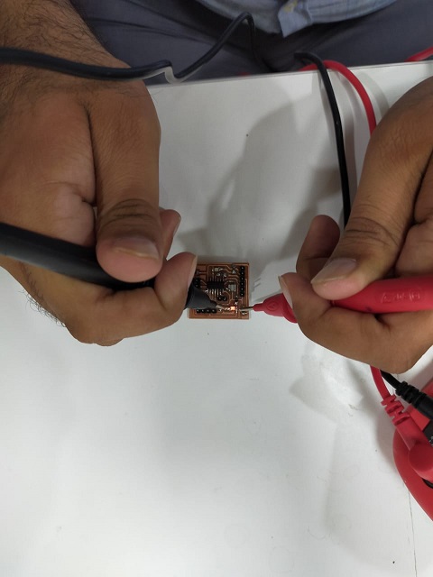
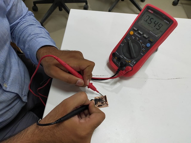
After milling and soldering first task is to check the connectivity of circuit. If any line will not be attached correctly to the IC or any component, our circuit will not work accordingly. In order to check the connectivity, rotate the dial on multimeter to diode and select the beep button. Then put anode and cathode of multimeter to that line which is supposed to be connected. If you hear multimeter beep then this line connection is ok, else there is no connection.
LED test
Second test is to make sure that LED is correctly soldered and polarities of LEDs are correct. In order to test the LED, rotate the dial on multimeter to LED and put cathode to ground and anode to the supply side of LED. If led glow then LED is perfect in position. If LED do not glow, check the soldering and/or the polarity may be reversed.
Resistor test
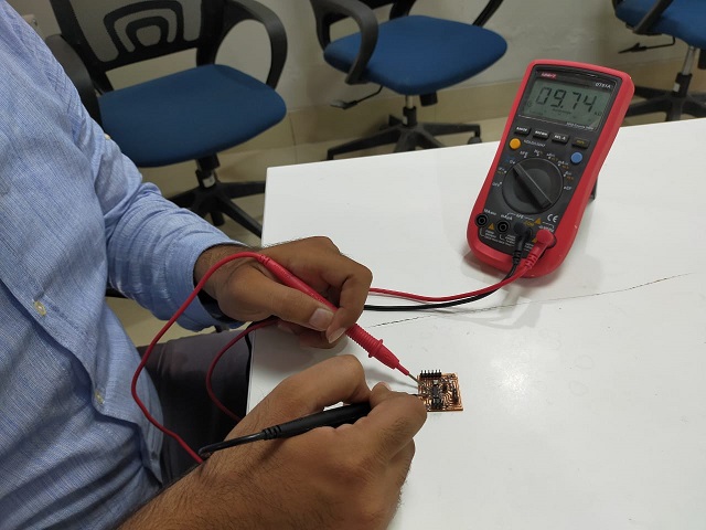
Resistors are very essential part of Electronics circuit. The value of resistor is very important. If we place resistor of wrong value at any place in circuit, circuit may not work or in some cases it can affect other components as well. Resistors are non-polarized. Rotate the dial of multimeter to resistance and put both probes of multimeter across the resistor. Value will be displayed on screen of multimeter.
Individual Assignment:
Redraw the echo hello world board. Add atleast one button and led. Check the design rules, make it and test it.
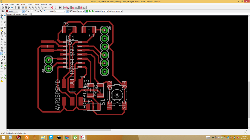
In this week, our assignment is to make Hello world PCB board. I took Attiny 44 board and redraw it. Task was to add At least one push button and led. I add one push button, one led and two digital pin headers for future use. First, we need a software to start making circuit. I choose EAGLE (Easily Applicable Graphical Layout Editor) software.
Eagle software
EAGLE is a scriptable electronic design automation application with schematic capture, printed circuit board layout, auto-router and computer-aided manufacturing features. EAGLE stands for Easily Applicable Graphical Layout Editor and is developed by CadSoft Computer GmbH. I am using EAGLE software from past 2 years. I found it very continent and powerful tool for PCB designing. EAGLE can be downloaded from here. After installation, set up libraries I started working. Here are steps to get started with Eagle to make Hello world board.
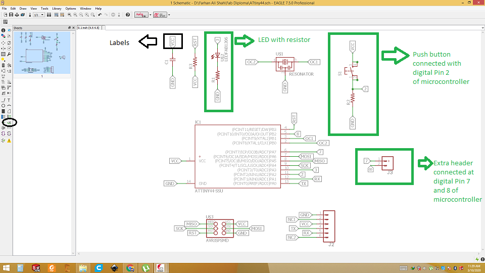
Open Eagle and search the components
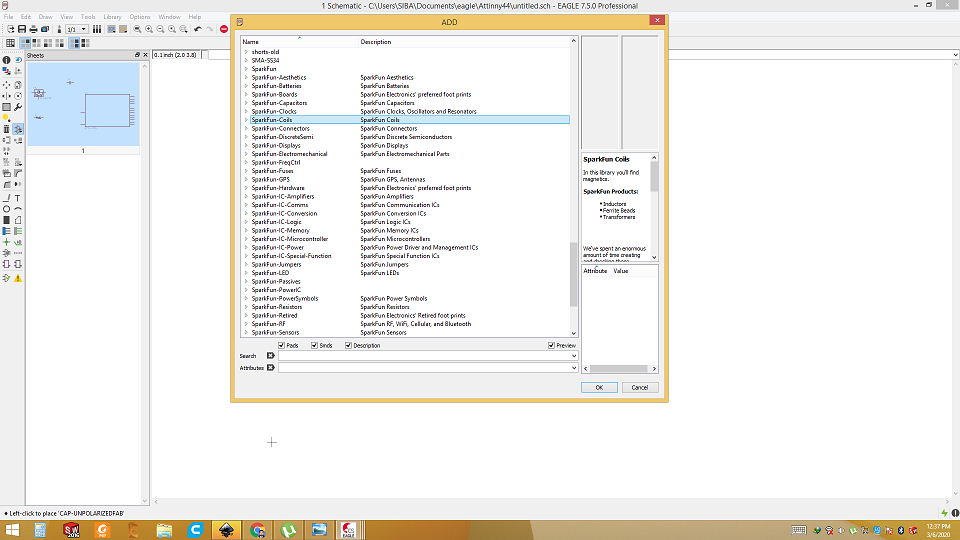
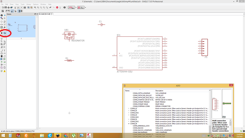
Take all the components from libraries and place in Schematic.
Using label connect each component with desired ic or components
Check ERC
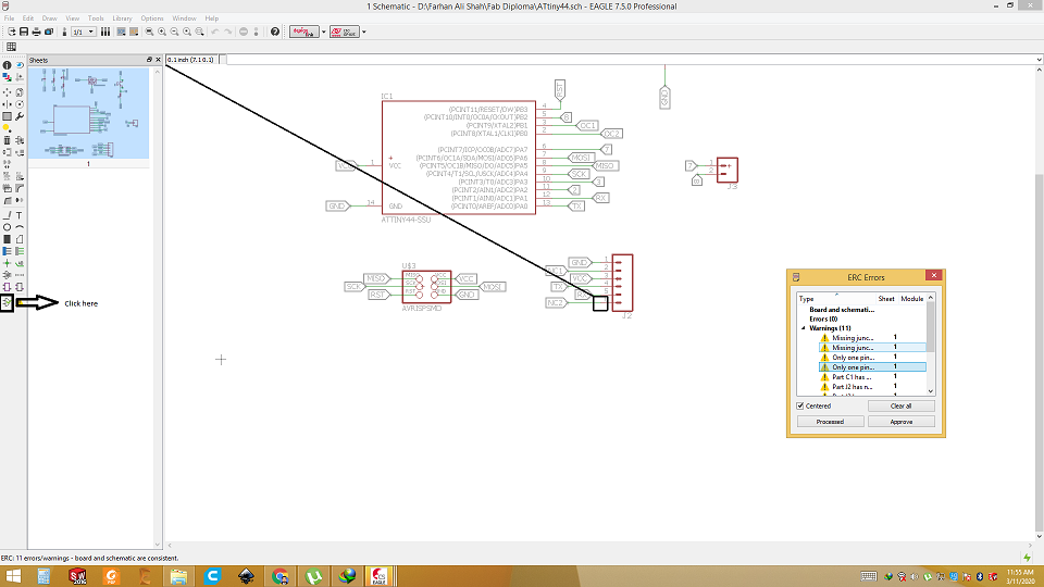
There is no error. Only warnings are due to un connected pins.
Switch to board layout
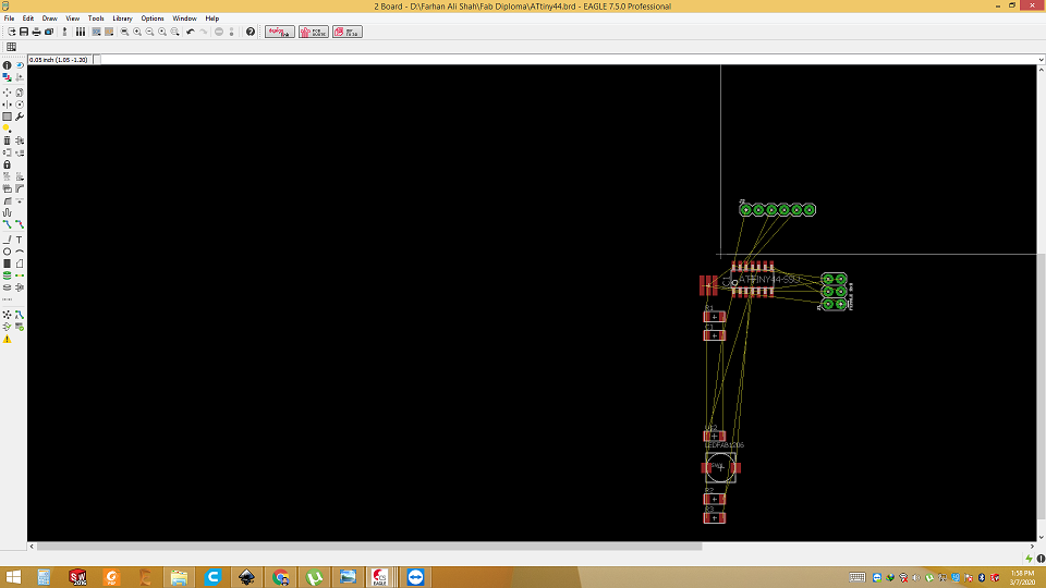
Route the wires in elegent way. Try to avoid any overlap.
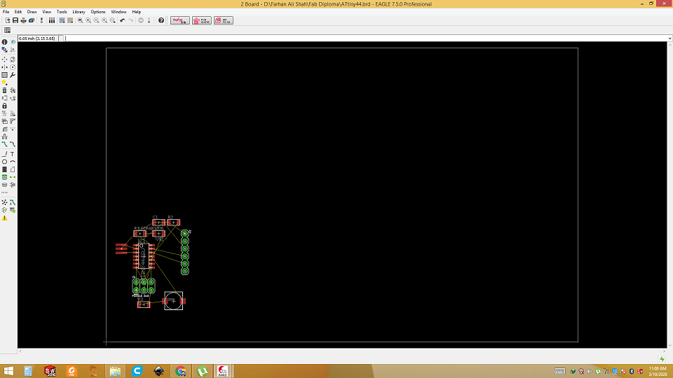
After routing
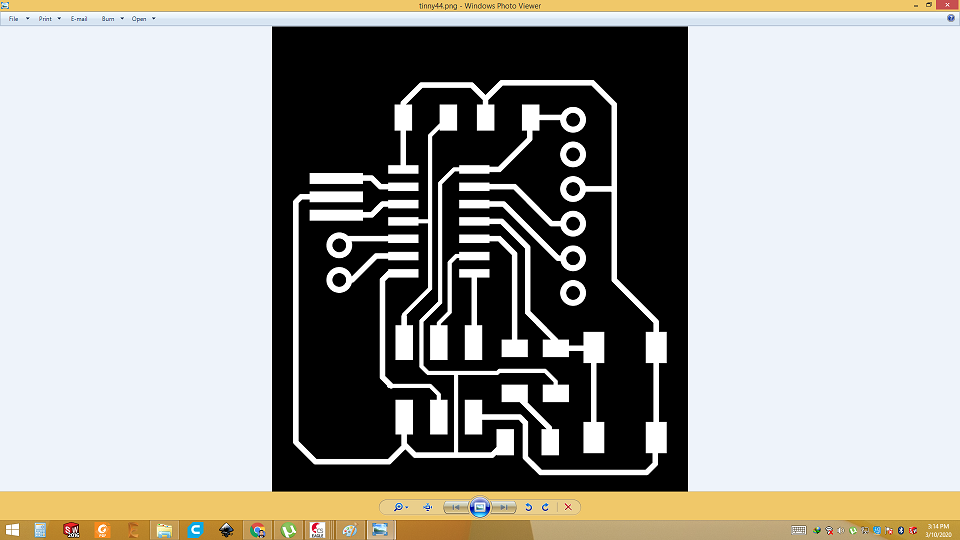
Generate PNG
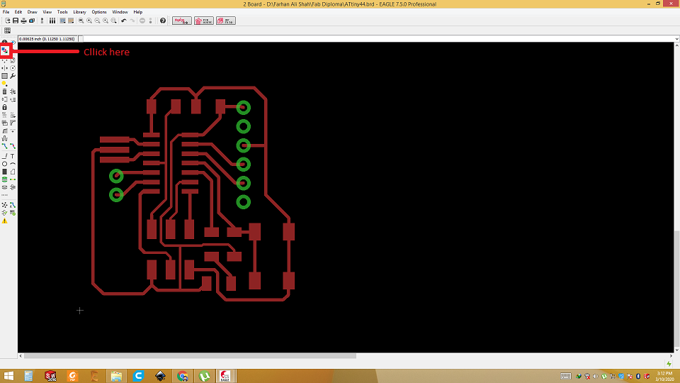
Generate PNG
RML is generated from PNG. So go to layer and select only Top, Pads and vias layers. These three layers are needed to generate png. Unselect all other layers. Then go to file and click export as png. Select the Monochrome and DPI as 600.
Export as image with monochrome.
Open mods
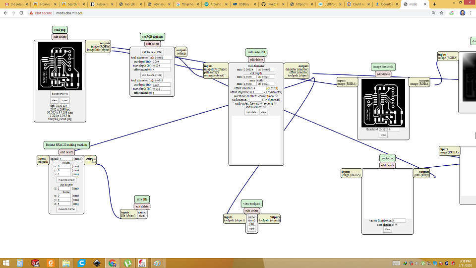
Mods is used to generate RML from PNG file. For traces, 1/64 bit is used and for outline and wholes (if you are using dip
components or connectors) 1/32 bit is used. Set the X, Y and Z starting coordinates and home position. Monochrome image is then imported into
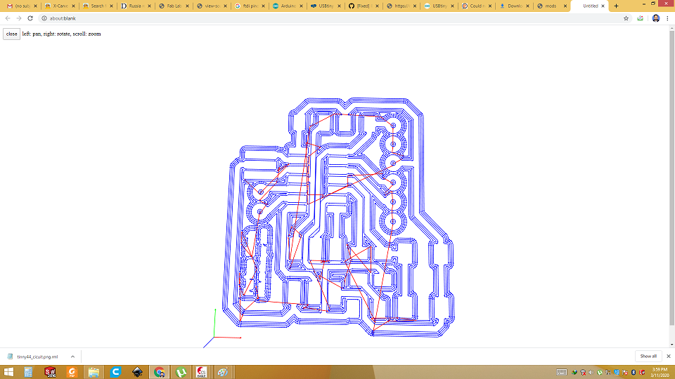
mods, select the tool (1/64 or 1/32), then click on calculate. After it finishes, click View to see the tool path.
RMl for traces
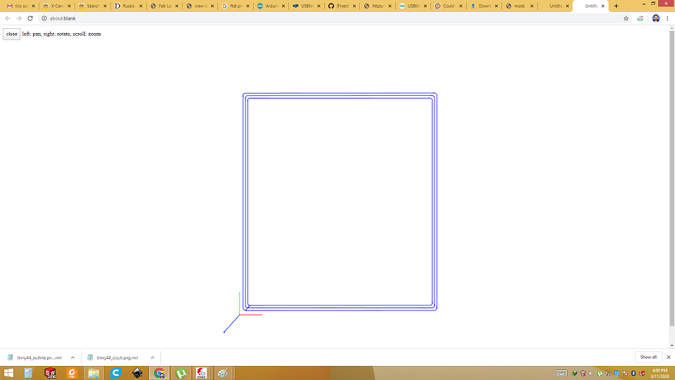
RML for outline
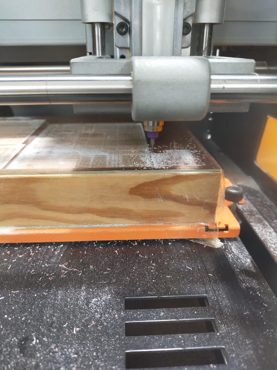
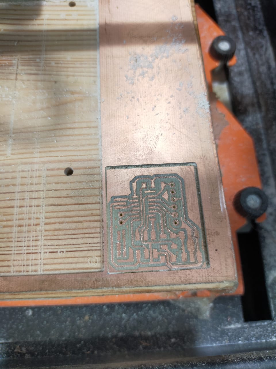
Milling
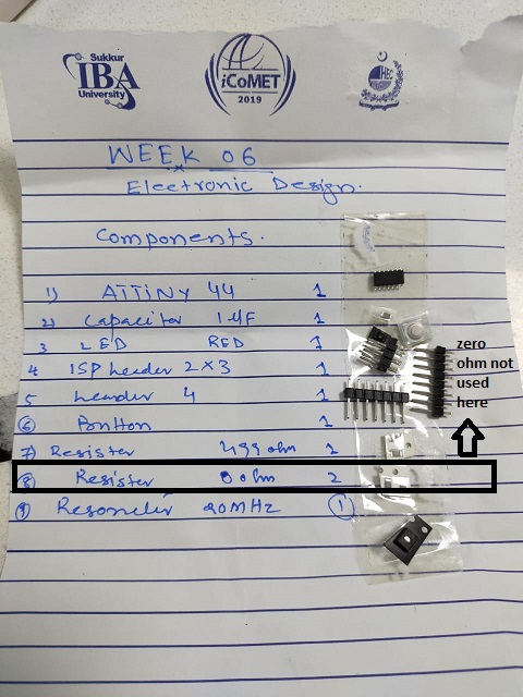
bill of material
Soldering and checking the connections
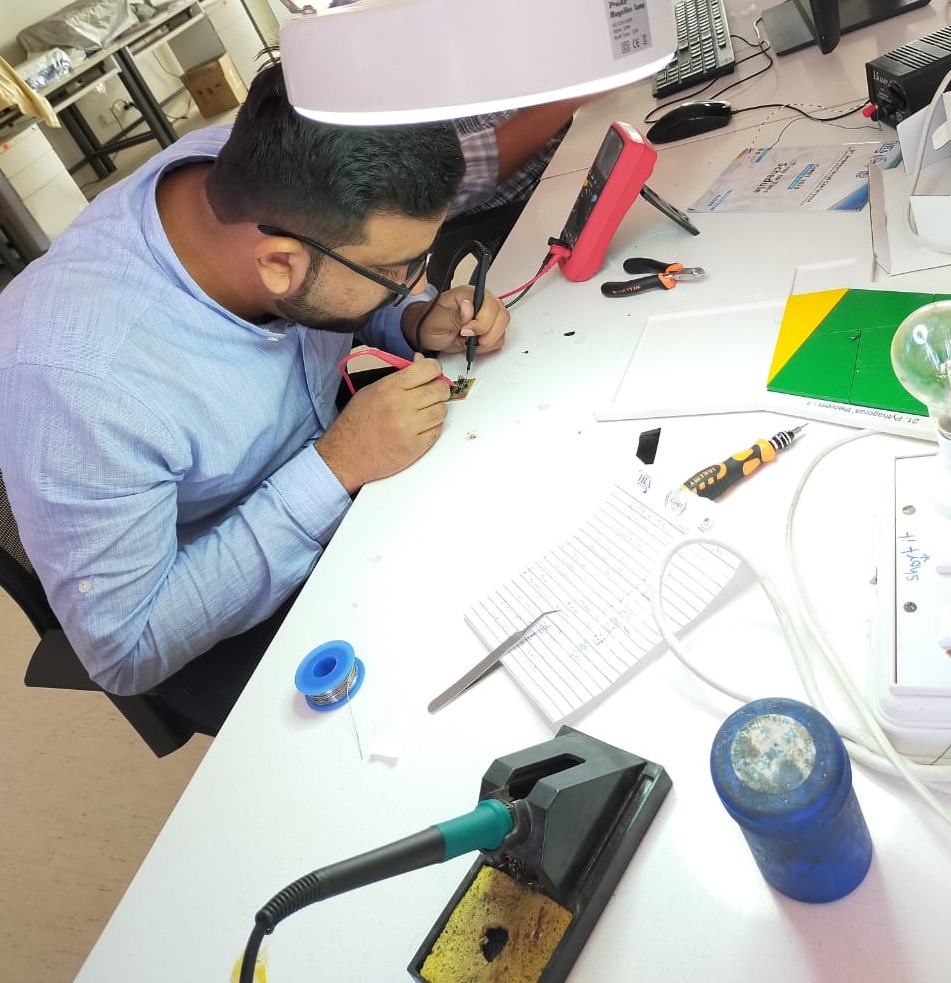
Solder the IC first then small components to big components
Final
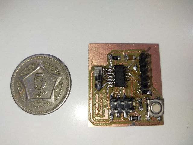
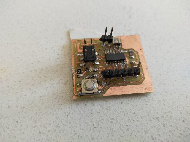
I put a lot of flux that why it is looking like this
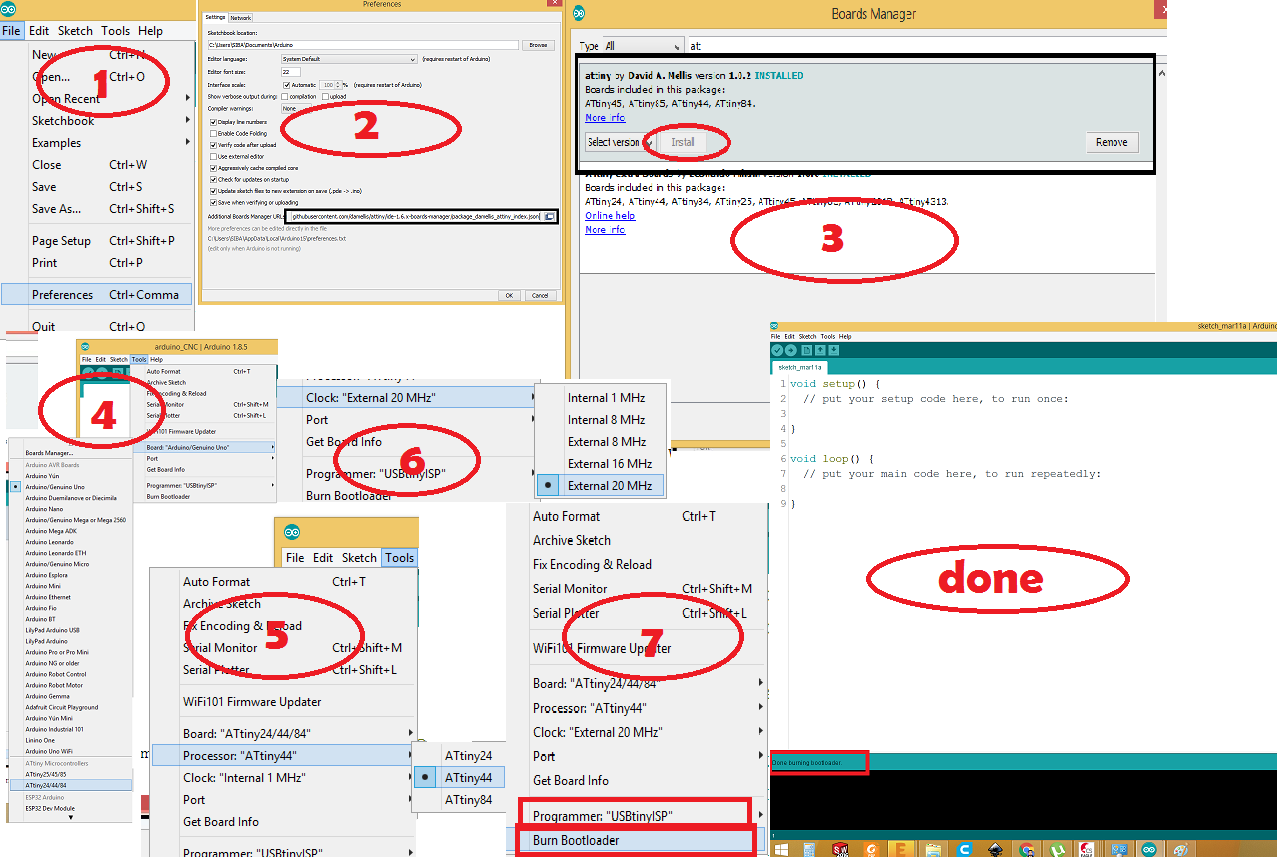
Bootload the IC
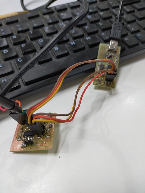
Connect ISP with newly milled and soldered board. And connect both with PC via USB.
Follow the following step to boot load the Microcontroller ic
Now upload the blink test code
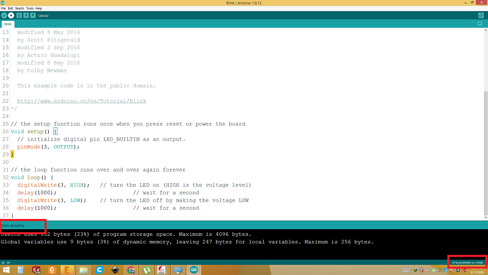
Final test
Download all files from here

This work is licensed under a Creative Commons Attribution-NonCommercial-ShareAlike 4.0 International License.