Group Assignment:
Test runout,alignment, speeds, and toolparths for your machines.
Making test card for press fit and different shapes
First of all we decided to make a test card so that we get to know machine. It is good way to know the process of machine as well as limitation of machines. In our assignments press fitting is key component so we made design to check the different thickness of slots to check which slot is better press fit. Also we add different shape (half and full cut) to see how machine is cutting these shapes.
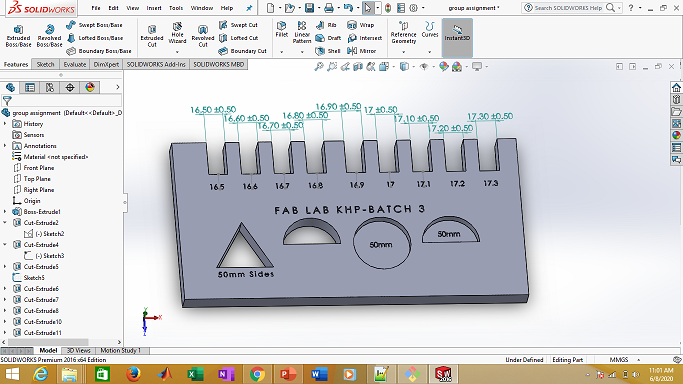
Design in solidworks
We design in solid-works. We put 0.5mm difference in each slot. We made circle (half and full cut) of 50mm diameter. Triangles of each side equals to 50mm.
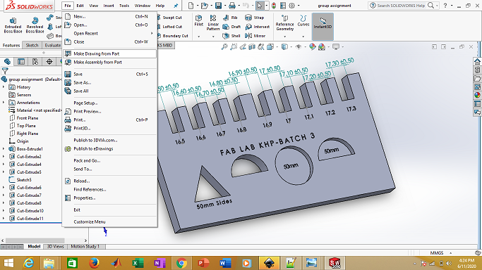
Make drawing from part
In order to cut on shop-boat, we need 2D file. So open file and select "make drawing from part".
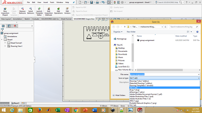
Save as .DXF file
Select the top view and drag it to the main area. Then save as .DXF file.
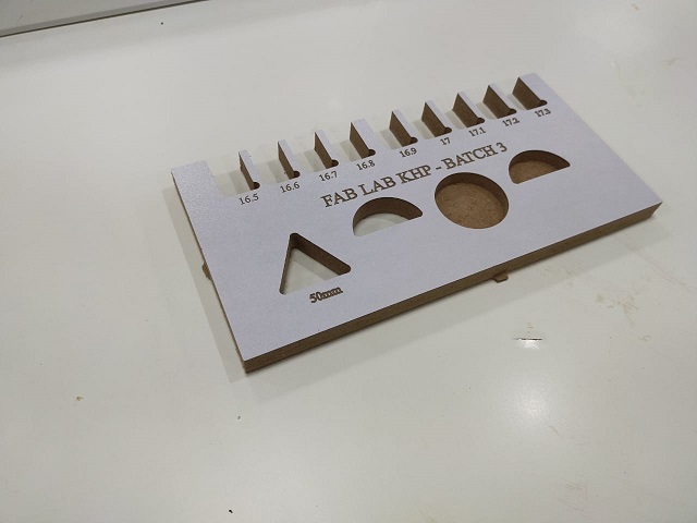
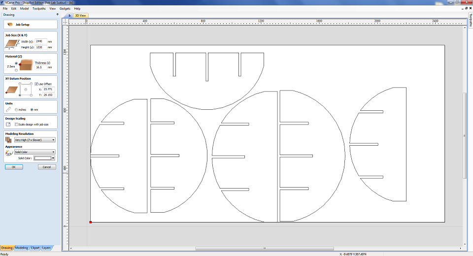
.DXF file is then opens in Carve and processes it.
Final result
Individual Assignment:
Make (design + mill + assemble) Some thing big
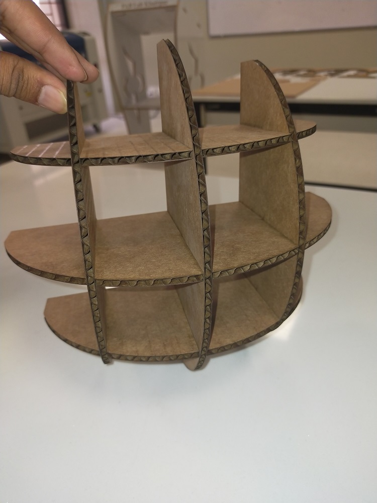
Wall hanging book Shelf
I searched a lot on internet to get the idea about the furniture stuff like that, then I found this wall handing shelf I really liked this design and idea so I decided to make this kind of design for this week.
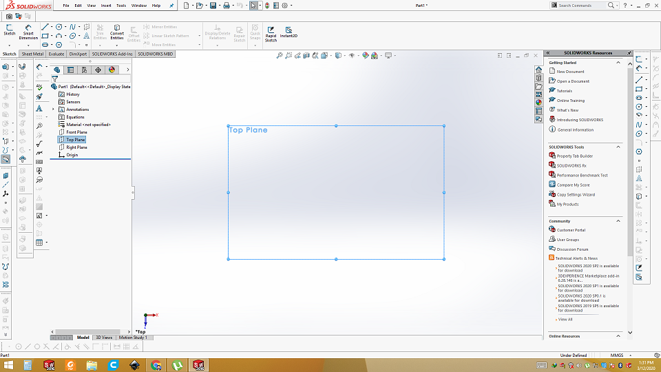
Open solid works and select the plan
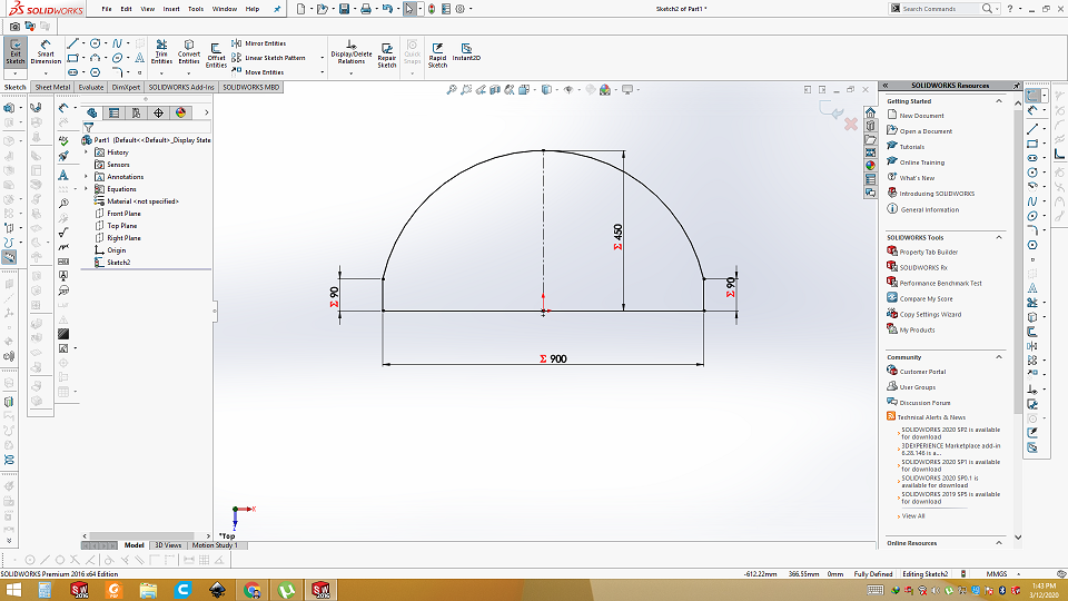
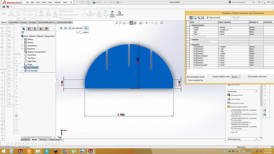
Sketch the first part of shelf using parametric equations
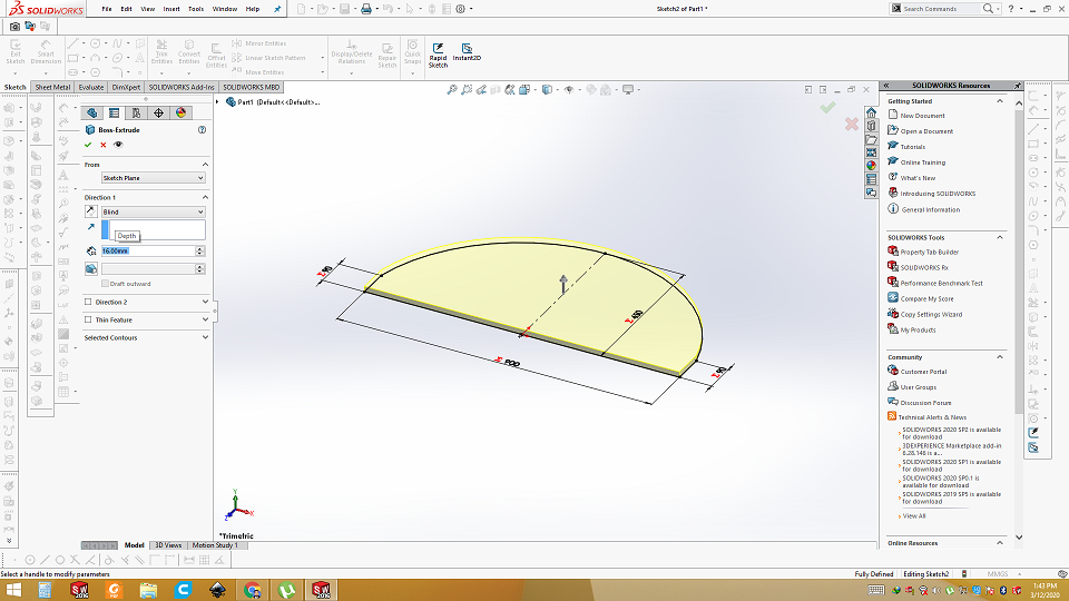
extrude the part
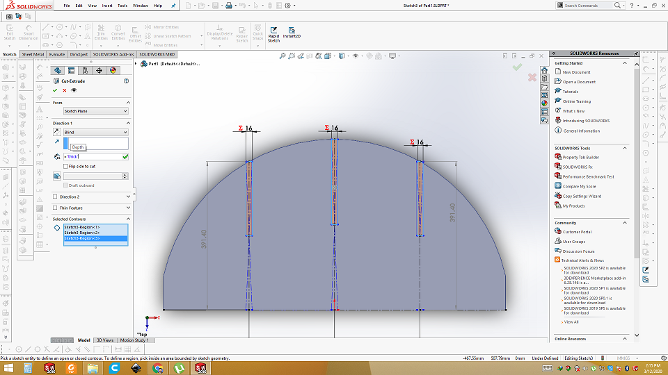
Make slit in the extruded design
We want press fit design so I am going to make slit 16mm wide and half in length because I am using 16mm OSB and this part will go into other part. Half will be cut on other part, so it will be a perfect fit.
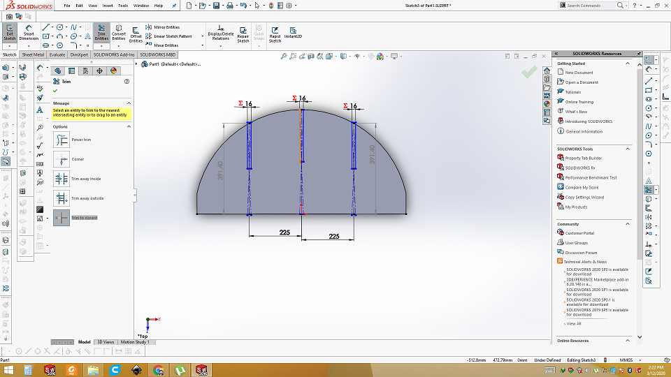
Cut the slit
Cut the slit using the cut-Extrude command in solidworks
Measurement of first part using parametric design
Center second part
This part is same as of upper part in measurement, only difference is that it slit at 180degree so the two parts may join each other perfectly.
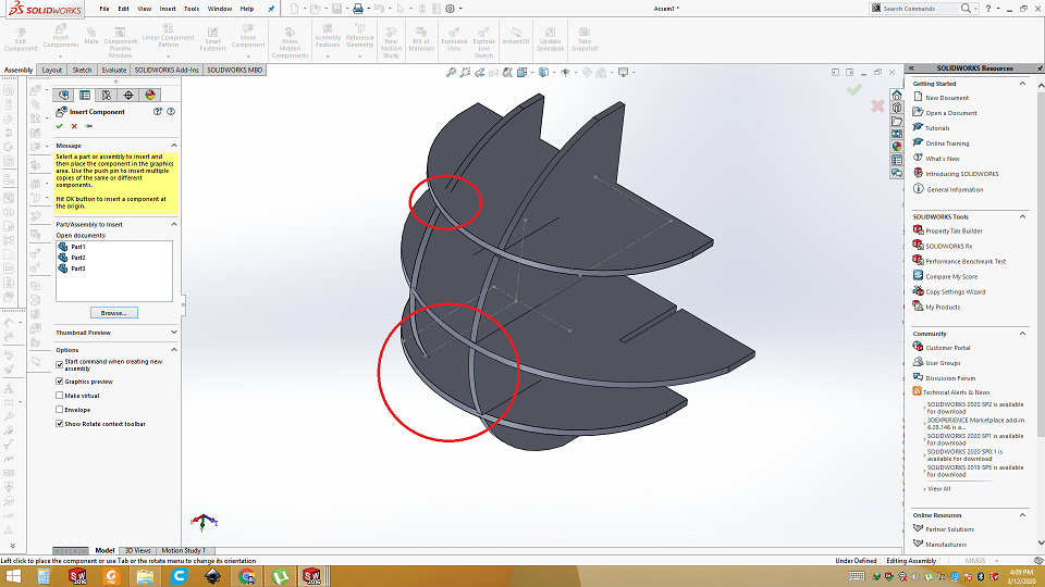
Side part without calculations
I tried to make side parts without calculation but when I assembled it, I found these mistakes.
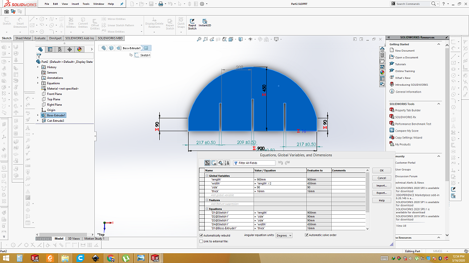
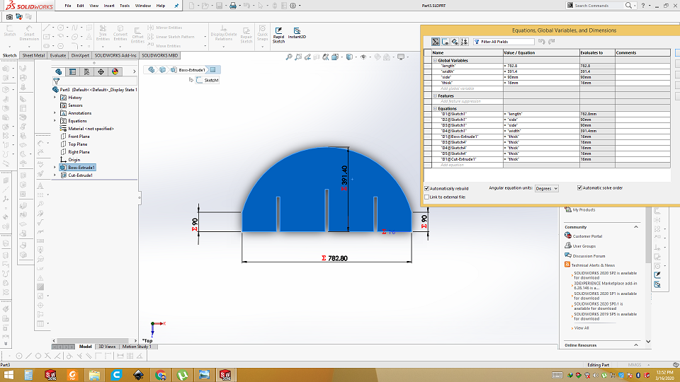
Side part after calculation
>First two parts are bigger parts. Length was 900mm and width was 450mm. Distance between the slits is 209mm, now side 4 parts will be smaller with same ratio. All parts are perfect circles. Length of second part is 782.80mm which is 900-782.8=117.2mm less than the first pair. Ratio of length to width is 2:1, having same ratio 117.2/2 = 58.6 now 450-58.6=391.4mm will be the width to align all. We need 4 parts of this measurement. Two with slits on up side, two on slits down side.
Assembled correctly
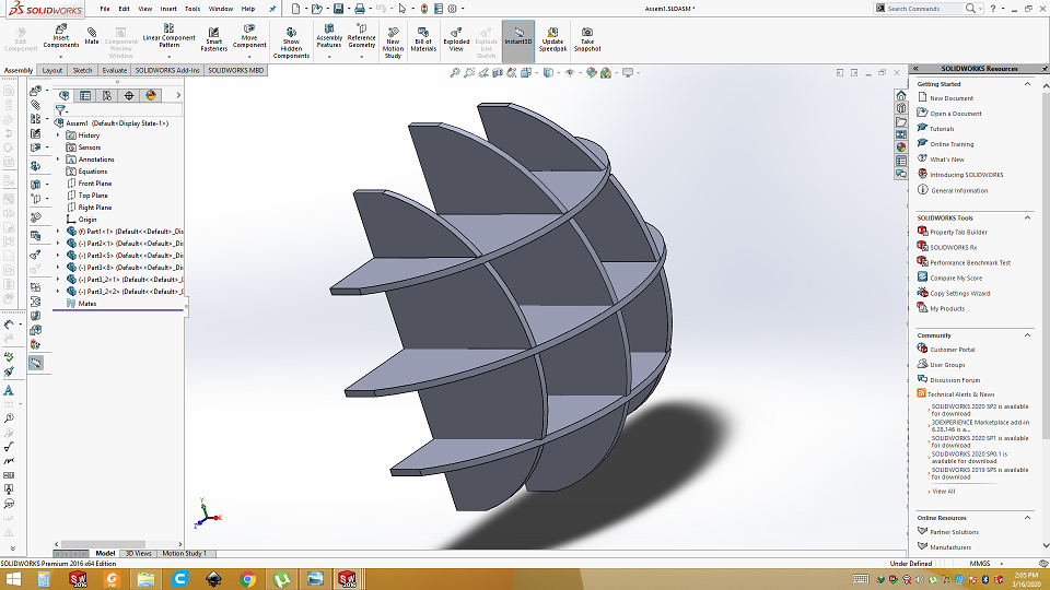
After successfully assembling in solid works, how it turns to check in physically but using laser cutter. .DXF is opened in the inkscape and down scaled it to 25%. Slit was of 16mm now it becomes 4mm. So I need the 4mm card board to check.
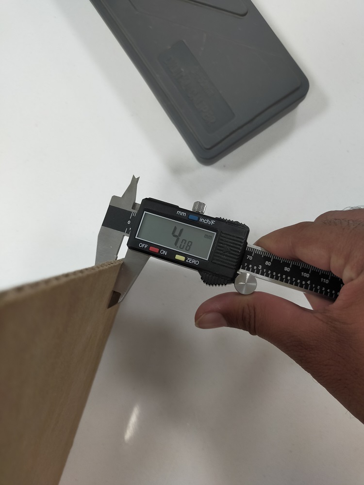
Measured the Card board
Then laser cut
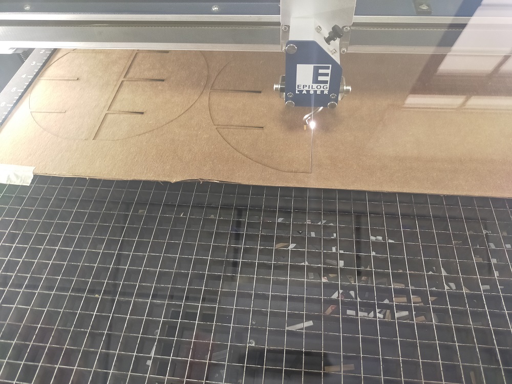
Assembled
Result are very good. It perfectly alligned and press fit.
Now it is time to cut on wood. So I choice the double sided laminated OSB board.
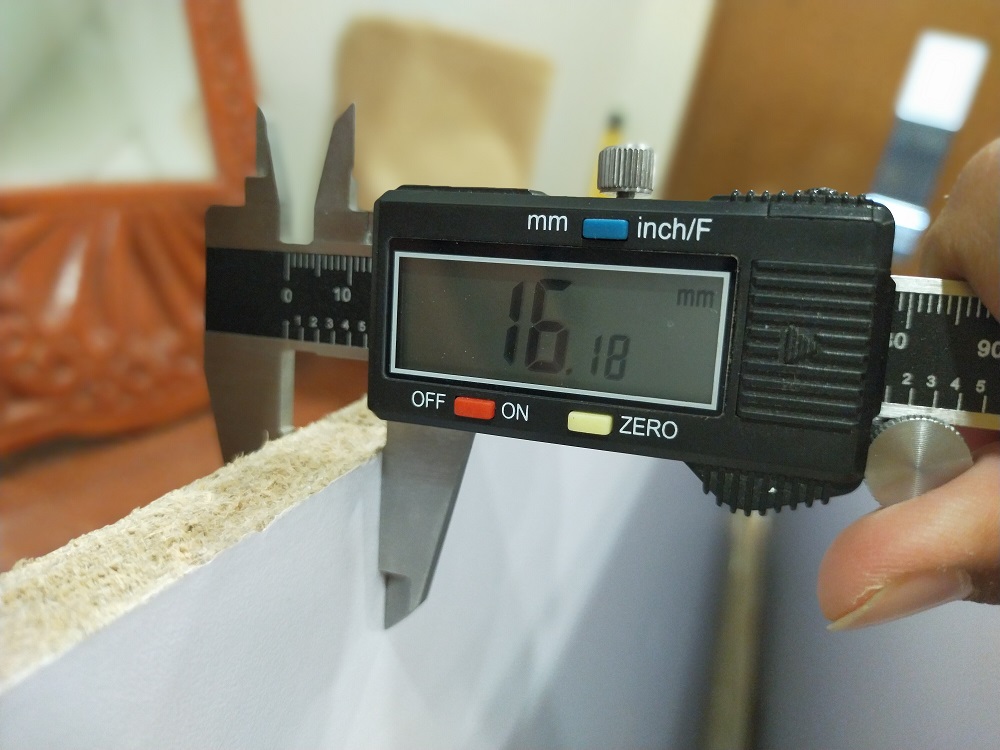
Measure the thickness from different side.
In order to get the average thickness, measure the thickness from different sides. Board has some variation in thickness.
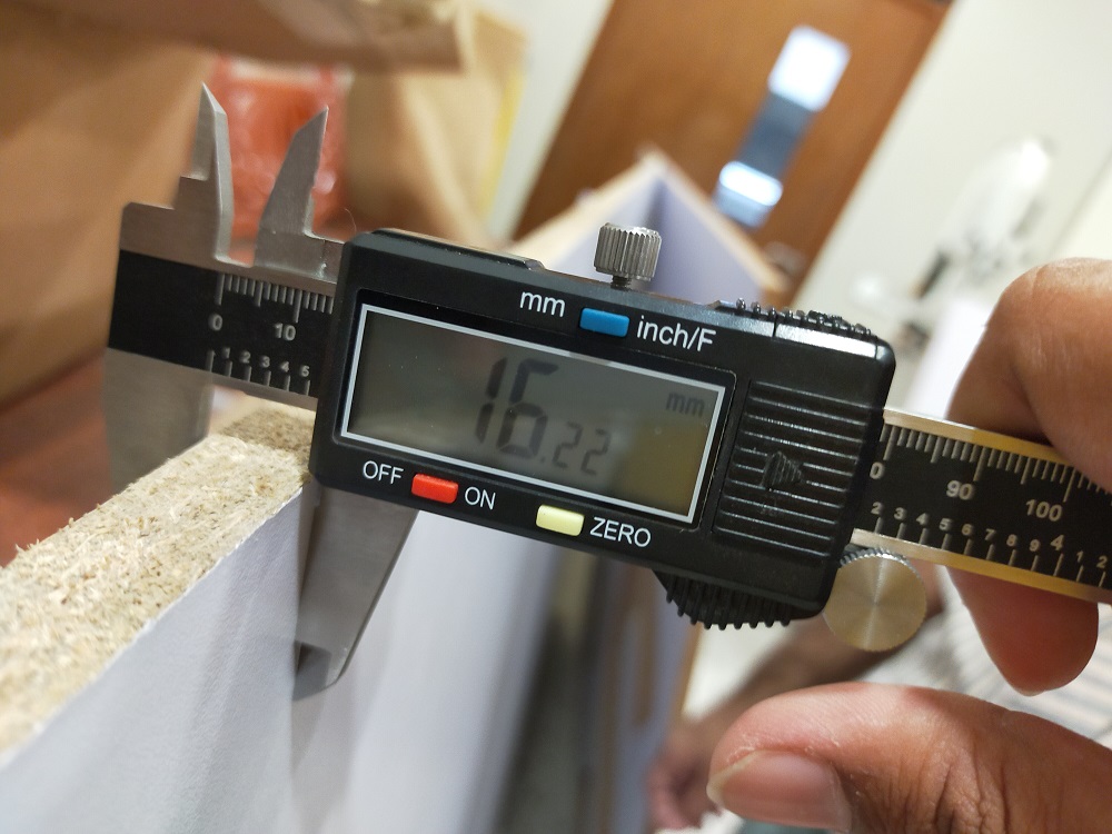
Measure the thickness from different side.
Vcarve Software
I choose Vcarve for tool path generation. VCarve Pro provides a powerful but intuitive software solution for creating and cutting parts on a CNC Router. VCarve Pro gives you the power to produce complex 2D patterns with profile, pocket, drill and inlay tool paths. Along with this, it gives you the ability to create designs with v-carving textures as well as import and machine unlimited Vectric 3D clipart or single model files. The ‘Pro’ edition gives you unlimited job and tool path size, true shape nesting & job set-up sheets, ideally suited to a production environment.
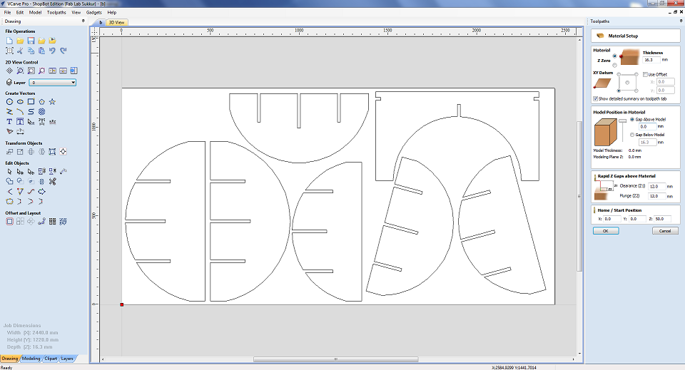
Now open Vcarve software
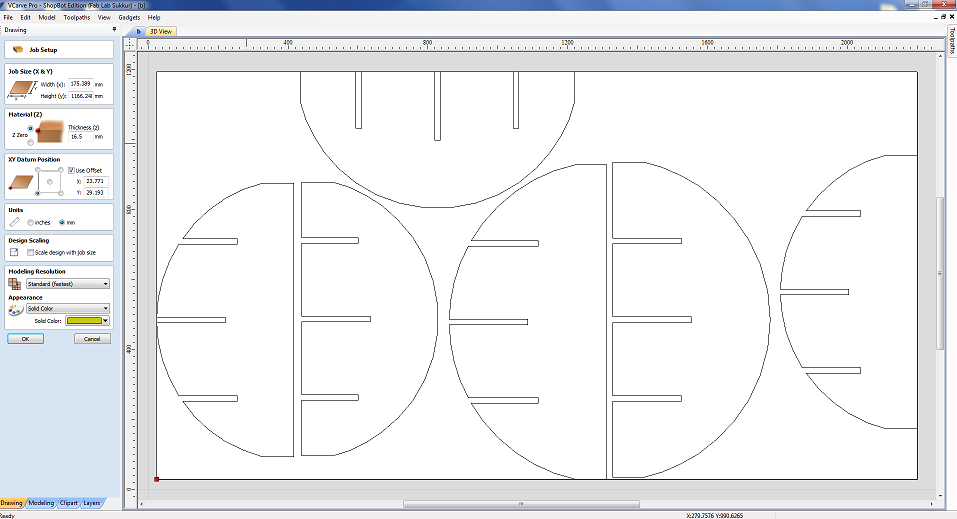
Select the size of board and thikness of material
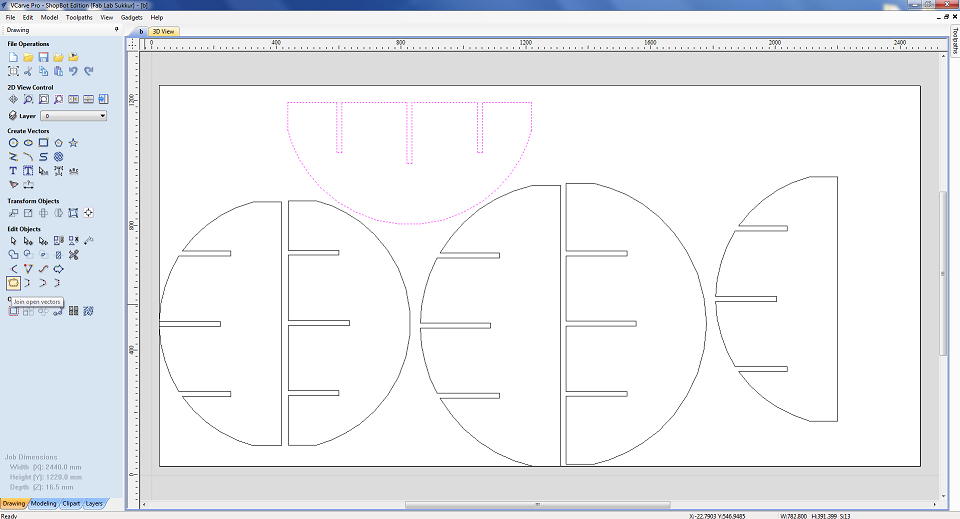
Check Join open vectors
Check if there is any open vector. Then join it. If there is any open vector tool path will not be generated correctly.
Mark a safe off set bondery
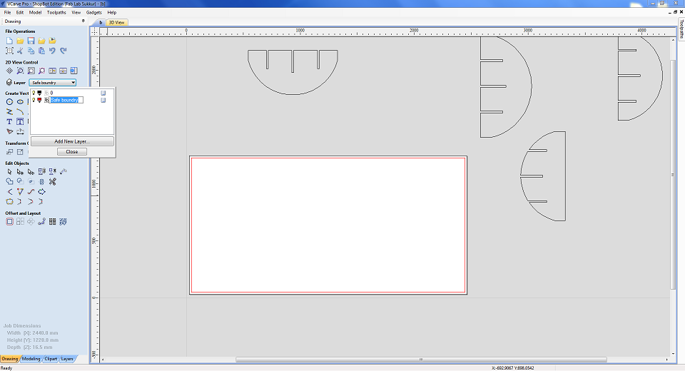
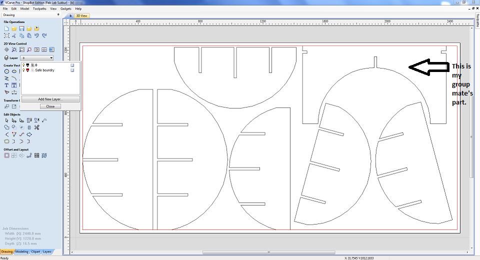
Place all the parts inside the bondery
We have placed the one part of my group in my board as there was some space in my board.
set the XY corner as start point.
Set the X and Y corner and also put the thickness of material. Please note if your selecting right top corner here then in shop controller it should be same when you will set the XY axis manually.
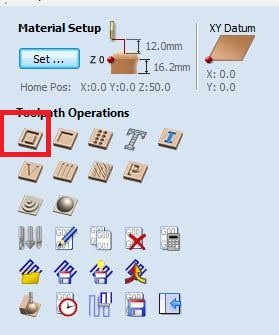
Tool path setting
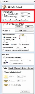
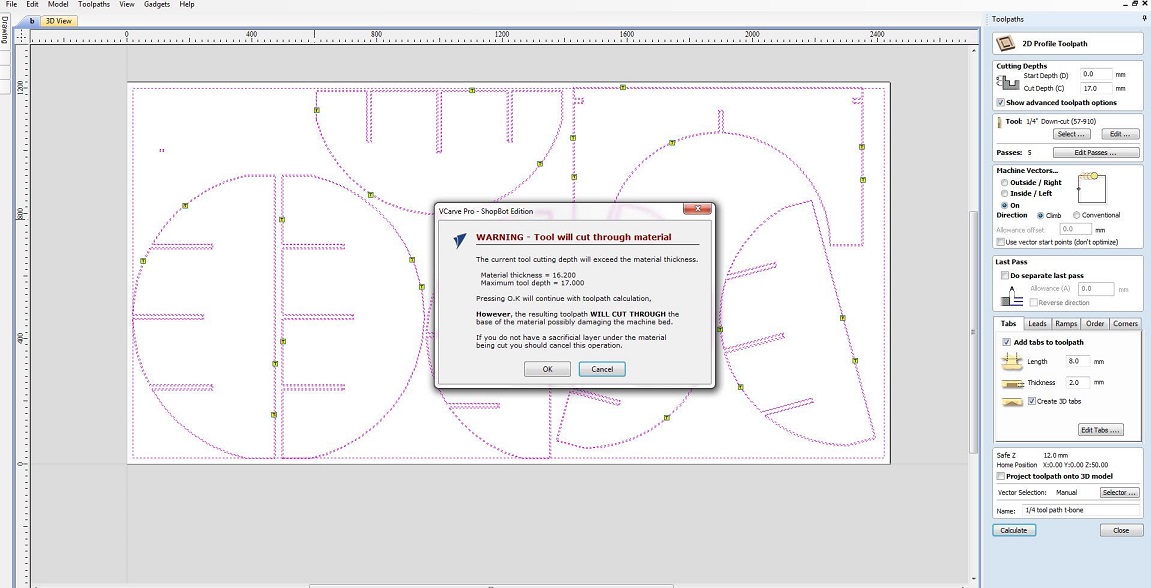
After material and XY setting now click on tool path profile. New window will apprear. Setting of toolpath will be done here. First of on the top is cut dept setting. We want to cut through so start cut should be "0" and cut depth should be greater than thickness of material. Material thickness is 16.22mm so i put cut depth 17mm. Please note that Shopboat must have sacrificial layer.
Tool type
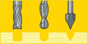
Before selecting the tool for our job let's learn more about tools type.
There are various types of CNC cutting tools and these tools are designed for high-precision machining. Most often, manufacturers make use of CNC cutting tools for near-perfection projects requiring a high degree of accuracy and precision. Which of the CNC cutting tools used is dependent on the project, operation pattern, and, most importantly, the CNC machine itself. Some CNC cutting tools are:
End Mills
Rotational cutting tools that you can use for the removal of materials. Although very similar to the drill bit, the end mill is for more versatile machining operations. Unlike the drill bit that cut axially to the material, end mills are lateral cutting tools that cut in any direction. Due to their design, some end mills cannot cut materials axially. Generally, there are different types of tip shapes for an end mill and each end mill depends on the desired end-product.
Types of End Mills
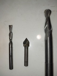
Ball nose mills
Ideal for 3D contour work, ball nose mills have rounded ends that produce top-notch curved surfaces
V-bit
Depressions that these tools make are V-shaped. V-bit can be 90o or 60o and each depends on the angle of
depression that a material needs. Although they often use them to engrave signs on materials, they’re ideal for projects that need excellent
sharp edges.
Straight Flute End Mills
These CNC cutting tools are general purpose tools that offer top quality edges.
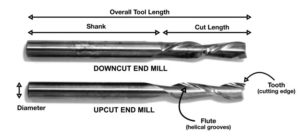
Down-cut and up-cut end mills
These spiral tools can either produce a smooth-surface finish by carrying the
residue chips down or a rough-surface finish by carrying the residue up and away from the specified area.The basic anatomy of an end mill consists
of a flute (helical grooves), cutting edge (teeth), diameter, shank, cut length, and the overall tool length.
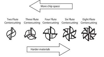
Number of Flutes
Flutes are the easiest part of the end mill to recognize. These are the deep spiraled grooves in the tool that allow for chip formation and evacuation. Simply put, flutes are the part of the anatomy that allows the end mill to cut on its edge.
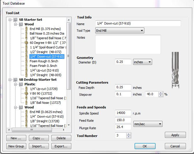
Select the Tool
I am using 1/4 downcut end mill. it has diameter of 0.25inch. Spindle speed of 14000rpm, feed 150mm/sec. It has two fluets.
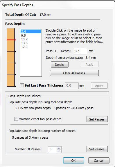
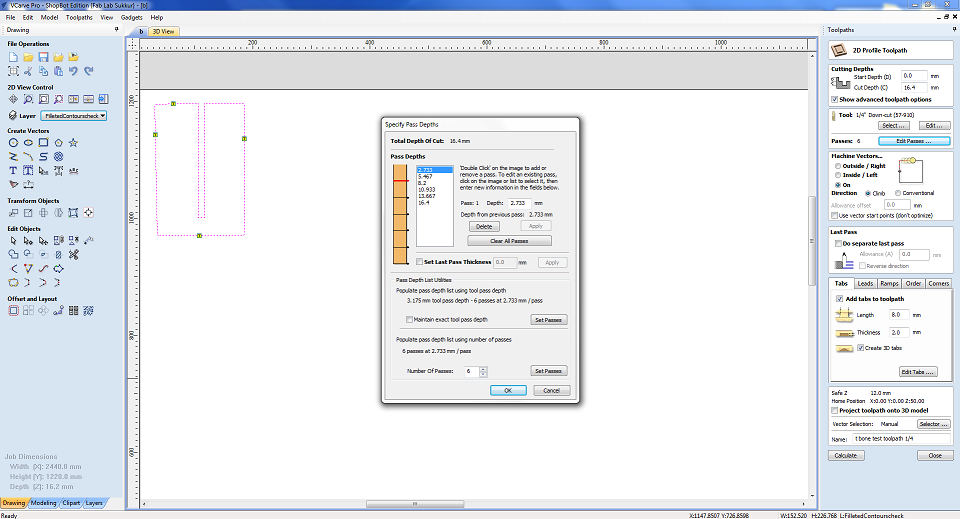
Pass depth
Your "depth per pass" settings can also cause bits to break. As a rule, your depth per pass should never exceed half of your bit's cutting diameter. I am using tool of diameter 6.35 so pass depth should be around the half of it. SO i choose 6 passes with 3.4mm depth.
Machine Vectors
Outside cut
Tool cuts through the material, running along the outside of a closed line in a manufacturing document/ blueprint.
inside cut
Tool cuts through the material, running along the inside of a closed line.
on-line Cut
Tool cuts through the material, running on the closed line in a manufacturing document/ blueprint.
Climb
Climb milling is when the direction of cut and rotation of the cutter combine to try to “suck” the mill up over (hence it's called “climb” milling) or away from the work. It produces the best surface finish.
Coventential
In Conventional Milling, the cutter rotates against the direction of the feed. During Climb Milling, the cutter rotates with the feed. Conventional Milling is the traditional approach when cutting because the backlash, or the play between the lead screw and the nut in the machine table
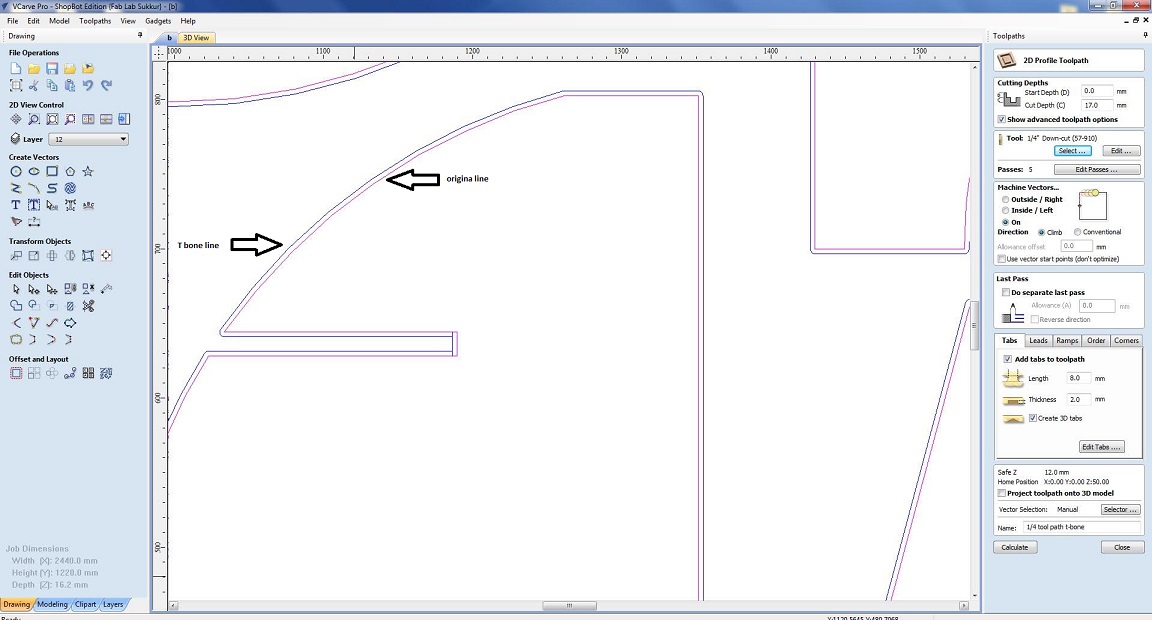
Choosing the Machine vector
Red line shows the original line of my design and blue line show the T bone design which is generated using gadget in vcarve. If we are generating tool path on red line so will select the outside cut. If we are generating tool path on blue line which is little away from original line so we choose on cut for perfect press fitting. I am using T bone so i choose On cut here. Along with i am using climb in direction.
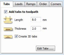
Add tabs
The tabs act as tiny bridges that hold the milled part to the stock material. The number of tabs depends on the part that you're cutting. Tick on the "Add tabs to the tool path". Write length and thickness of tabs in boxes. Cick on the tool path where you want to have the tabs.
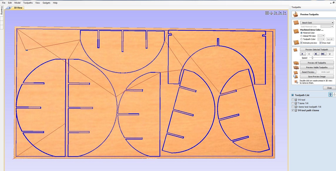
Complete Tool path setting and simulation
Here is the complete setting of toolpath. Name the tool path in below portion. Click calculate to generate the tool path and also it generate the simulations. Click ok and simulation is generated. You can play with play button. Also in left bottom you can see all the toolpaths.
take the slit and set the setting and also defined depth passes
As I was not sure that the setting will work or not in my press fit design . So I decided to test it by making one slit of 16mm and cut it.
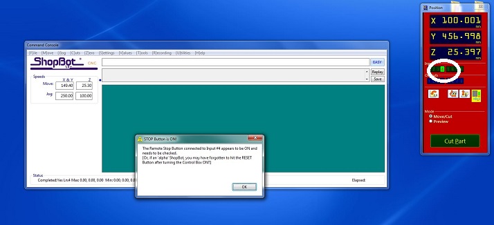
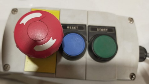
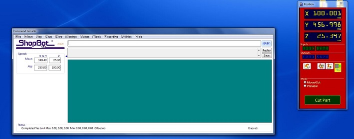
Open the Shopboat controller
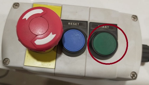
Open the shopbaot controller. LED 4 is on. We need to make it off using a start-up sequence of Shopboat. Without doing this, shopboat won't be functional. Start-up sequence is press the red button and then twist it according to arrow then press reset button. Repeat this sequence untill LED 4 is off.
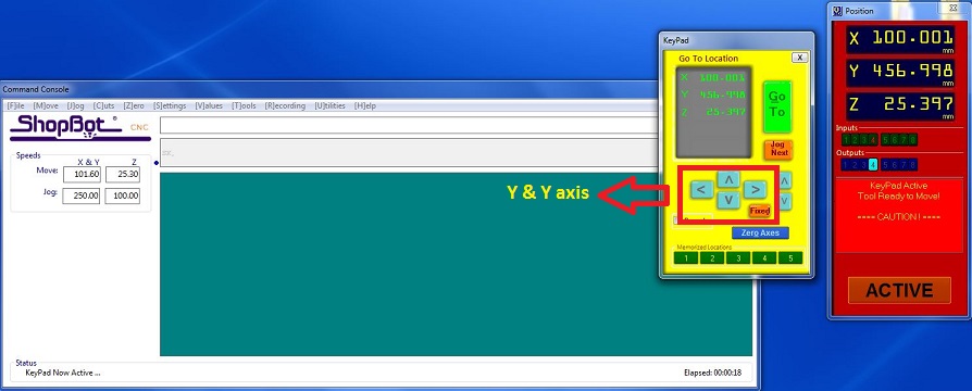
Set X,Y axis zero
Click on keypad. New window will apprear. Move the machine head using the arrow keys and move the head on the left corner of the sheet. Click on "zero axis" button. Check the X,Y and click the zero. X, Y axis are now zero.
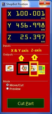
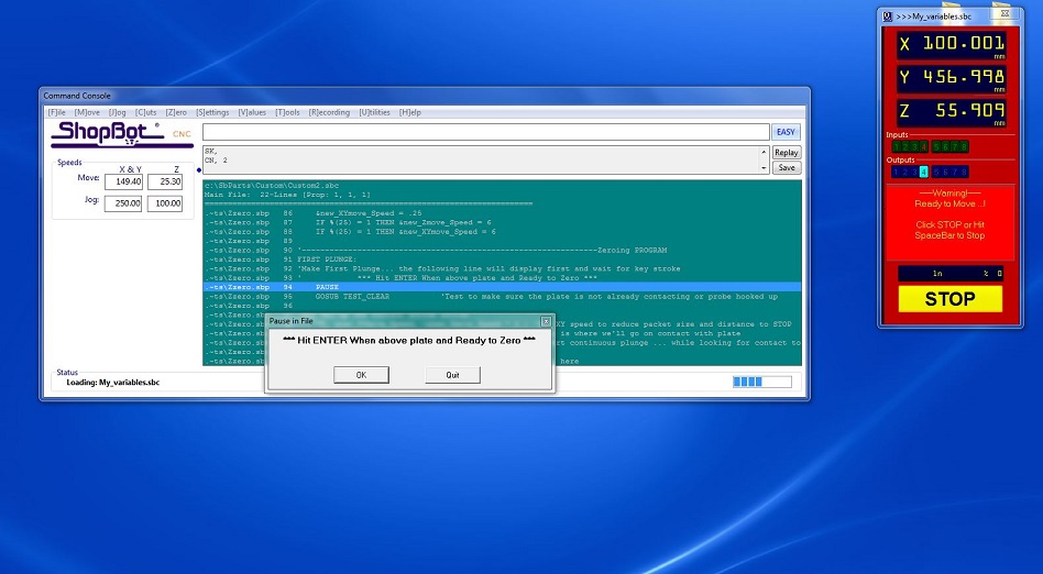
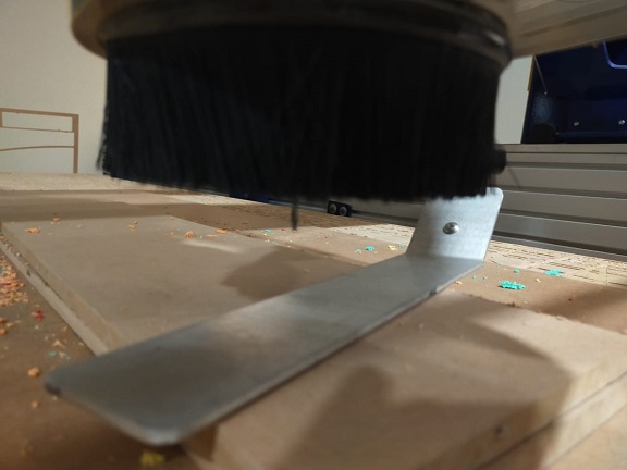
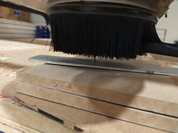
Set Z-axis zero
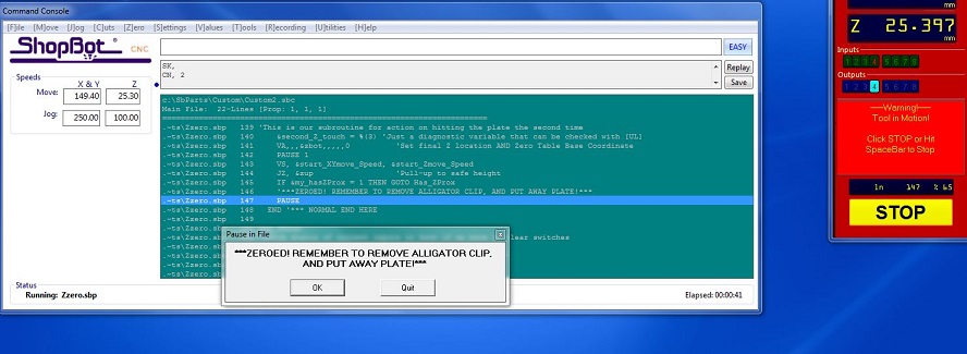
Click Z-axis zero highlighted above. Take a build plate and crocodile clip. Put the plate below the tool on the wood. Put the crocodile clip on the tool clap. After setting all this correctly hit enter. Tool automatically comes done and hit the plate then goes up then again goes down.
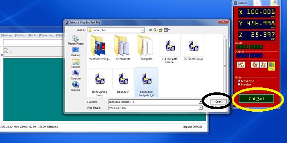
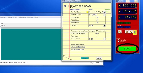
Open the tool path file and start the job
Click on the "Cut part". New window will be opened. Select the tool path file generated from Vcarve. Click open. Now file is loaded. Click the start to start the job.
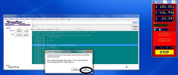
Start the spindle
Now notification will be arrive to start the spindle. First open the vaccum then push the start button on the Shopboat controller.
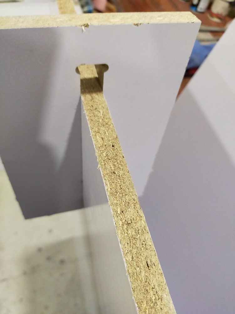
Tested it(worked perfect)
Above setting worked fine for press fitting. So now i am confident to use above toolpath setting for my entire design.
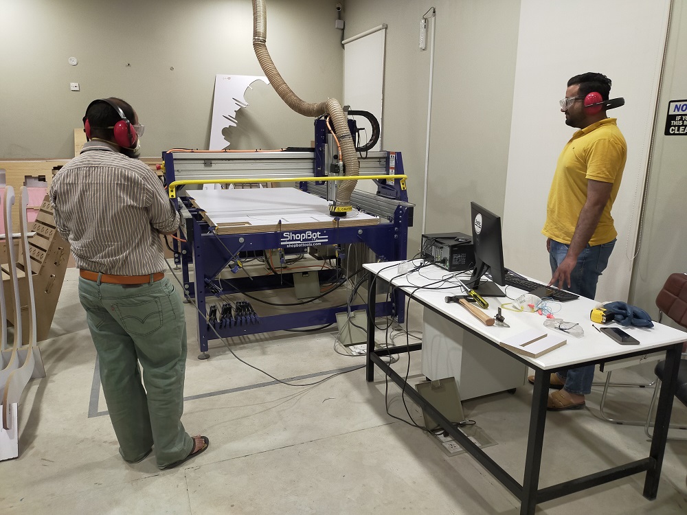
Cutting on shop boat
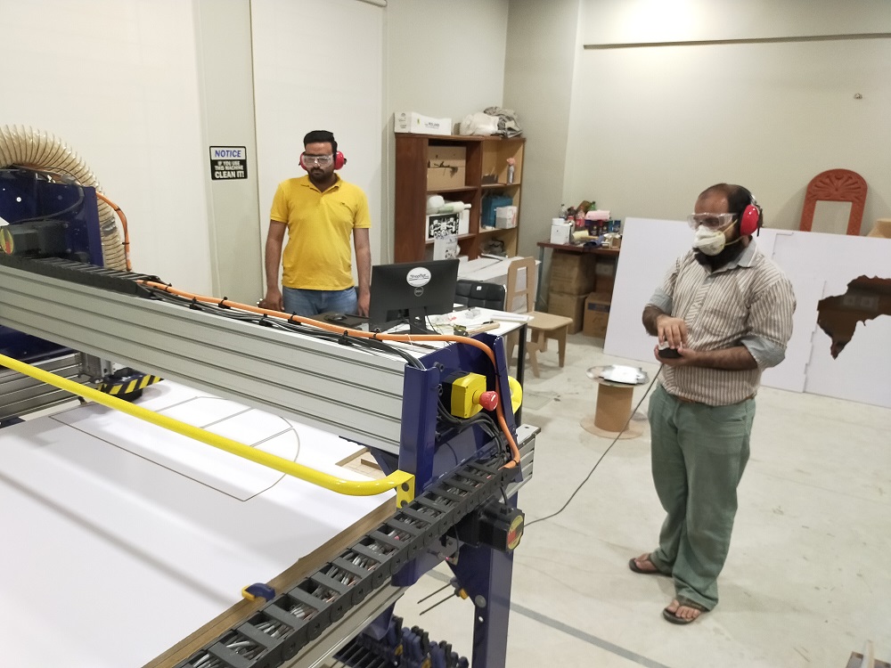
Cutting
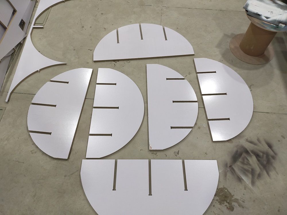
Result
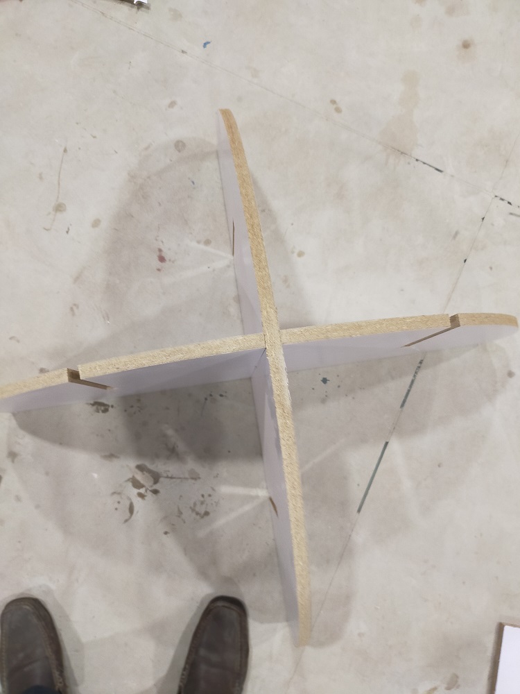
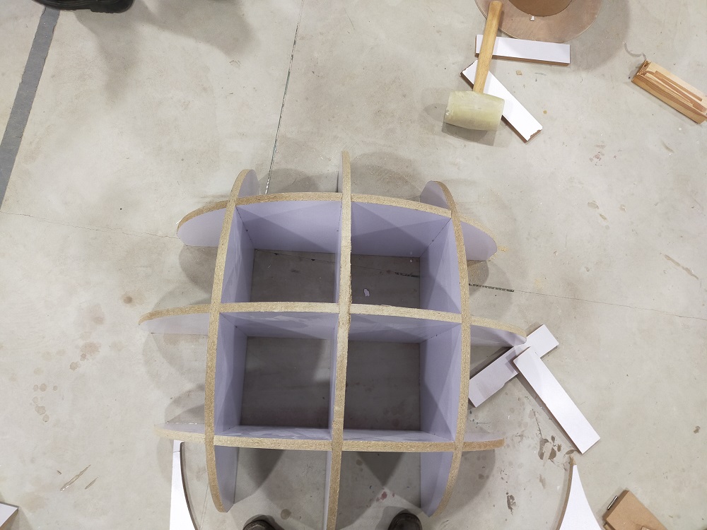
Startint to assemble
First two part went easly with little help of rubber hamer.
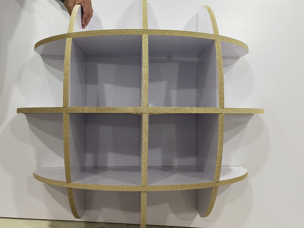
Assembled the complete
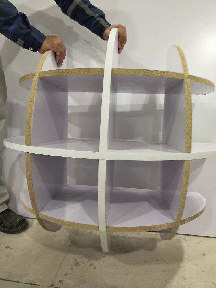
Last part took a lot of force because friction increase due to increase in number of sides. By help of rubber hammer and collogue I finally able to assemble it completely.
Aligned with wall and it perfectly alligned from all sides.
Use white strip to hide the rough area
Download all files from here

This work is licensed under a Creative Commons Attribution-NonCommercial-ShareAlike 4.0 International License.