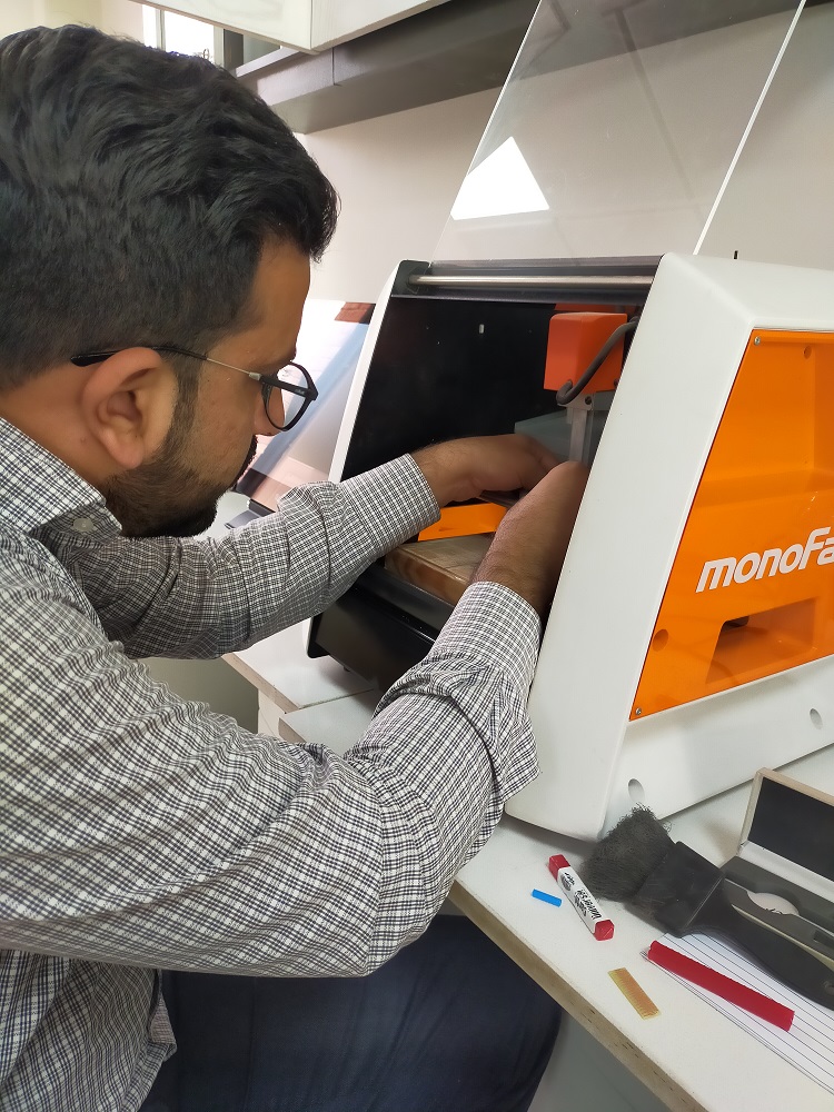
In this week we worked on PCB fabrication. We learned about how to use SRM 20 machine for PCB production. First of all we need to characterize the design rules for PCB and understand the process of PCB fabrication. We have taken bit characterization file from lecture siteand processed it. SRM 20 work on rml file. Mods is used to process the PNG file and produce the required rml file for SRM 20.
Following are the Steps for PCB fabrication:
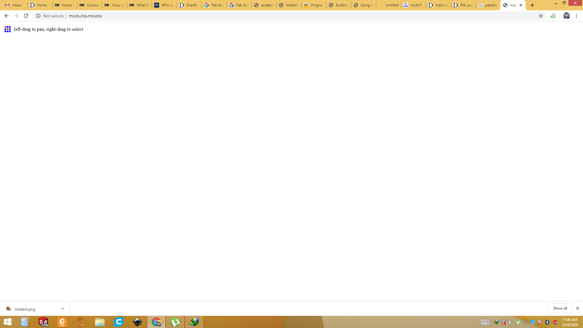
Step: 1 Open the Mods
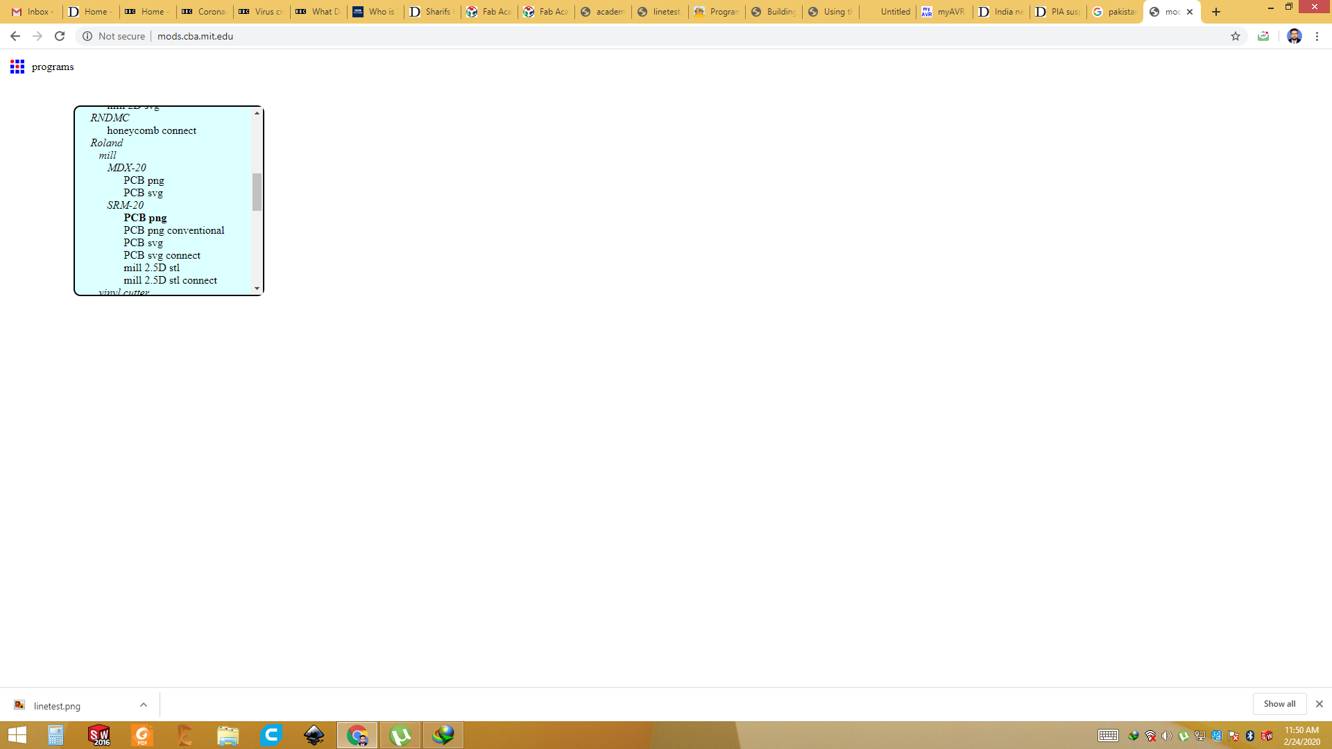
Step:2 Select "SRM 20" and "PCB png"
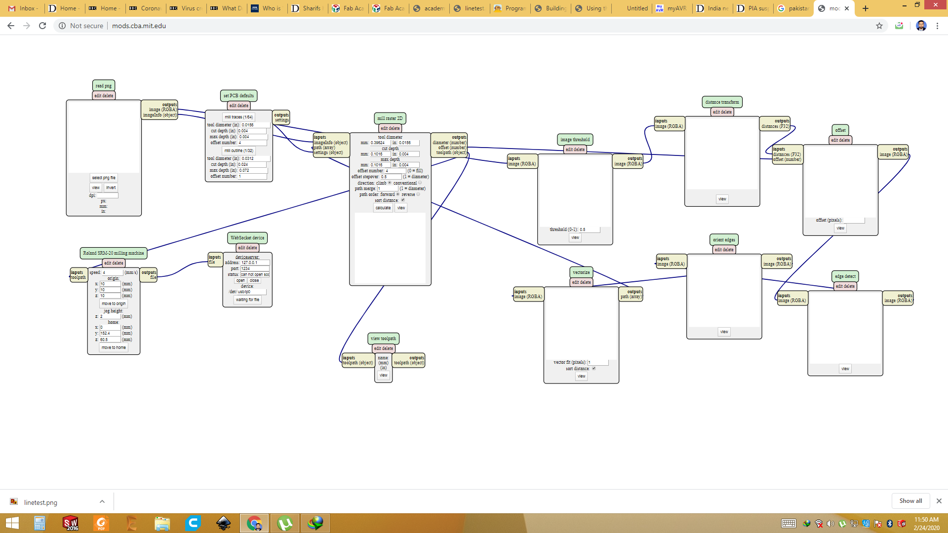
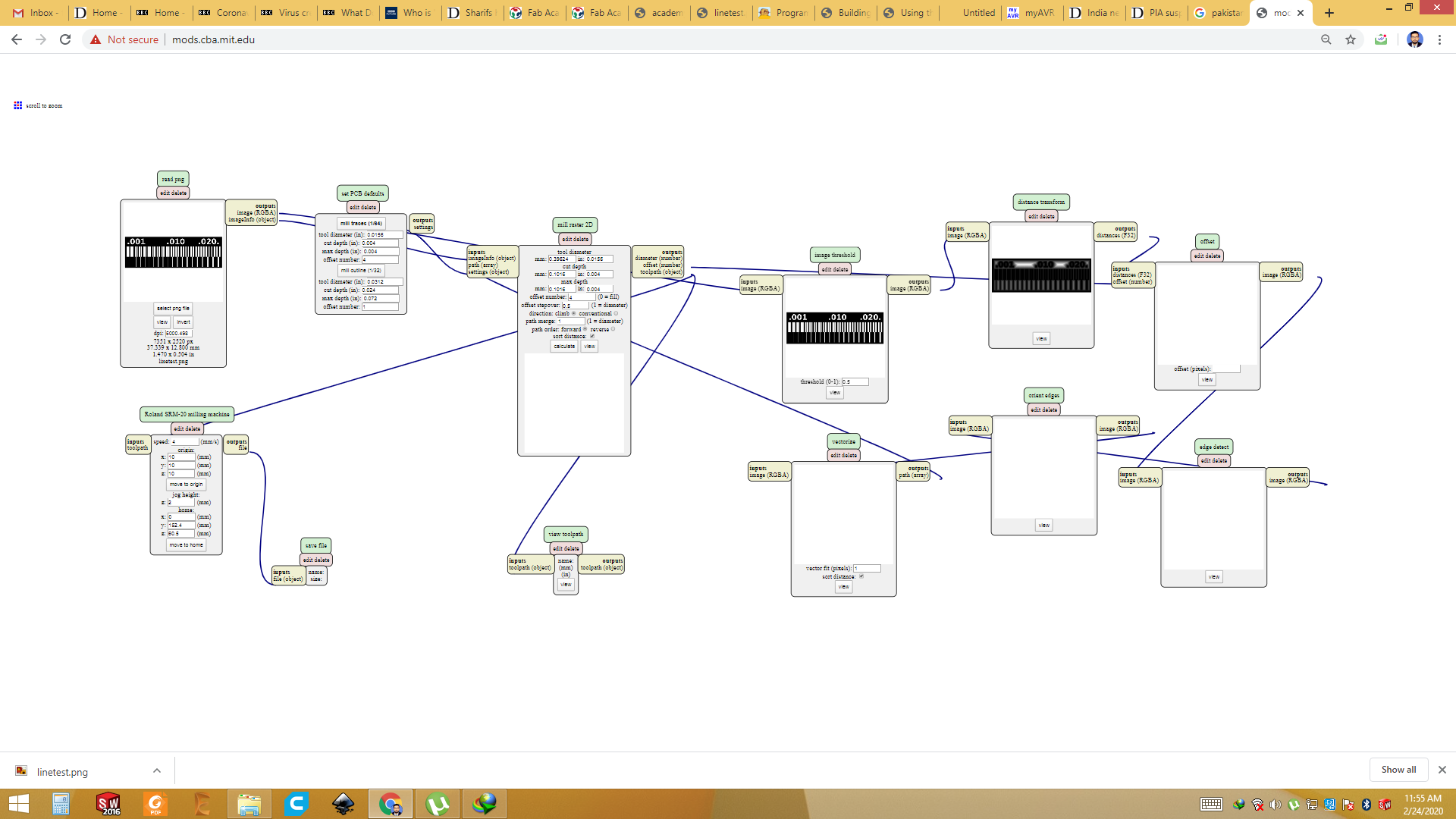
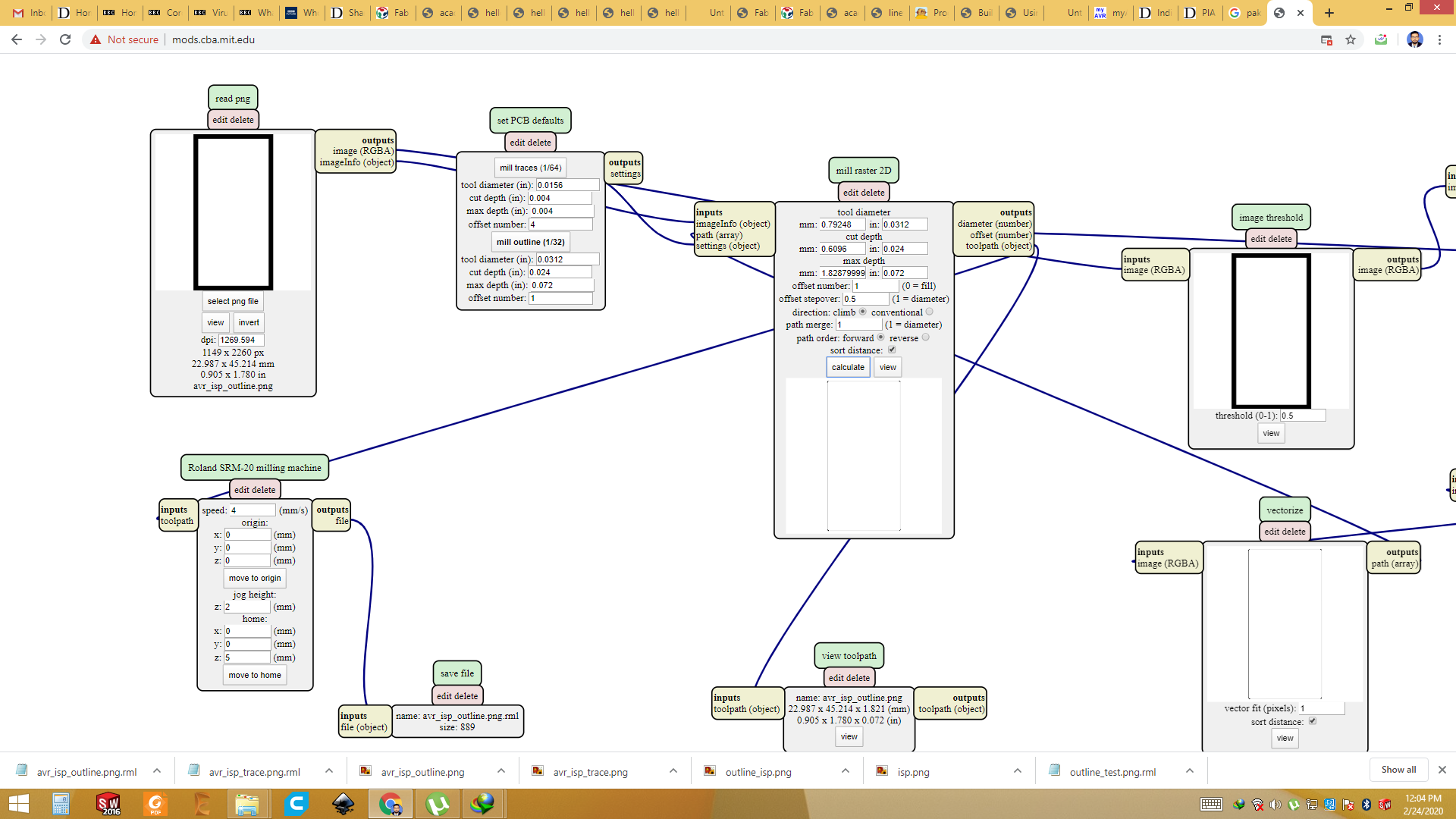
Step 3: Outlook of Mods for SRM 20 PCB
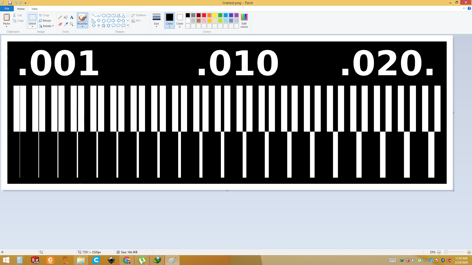
Step 4: Separate the trace and outline of Circuit using paint and save as PNG
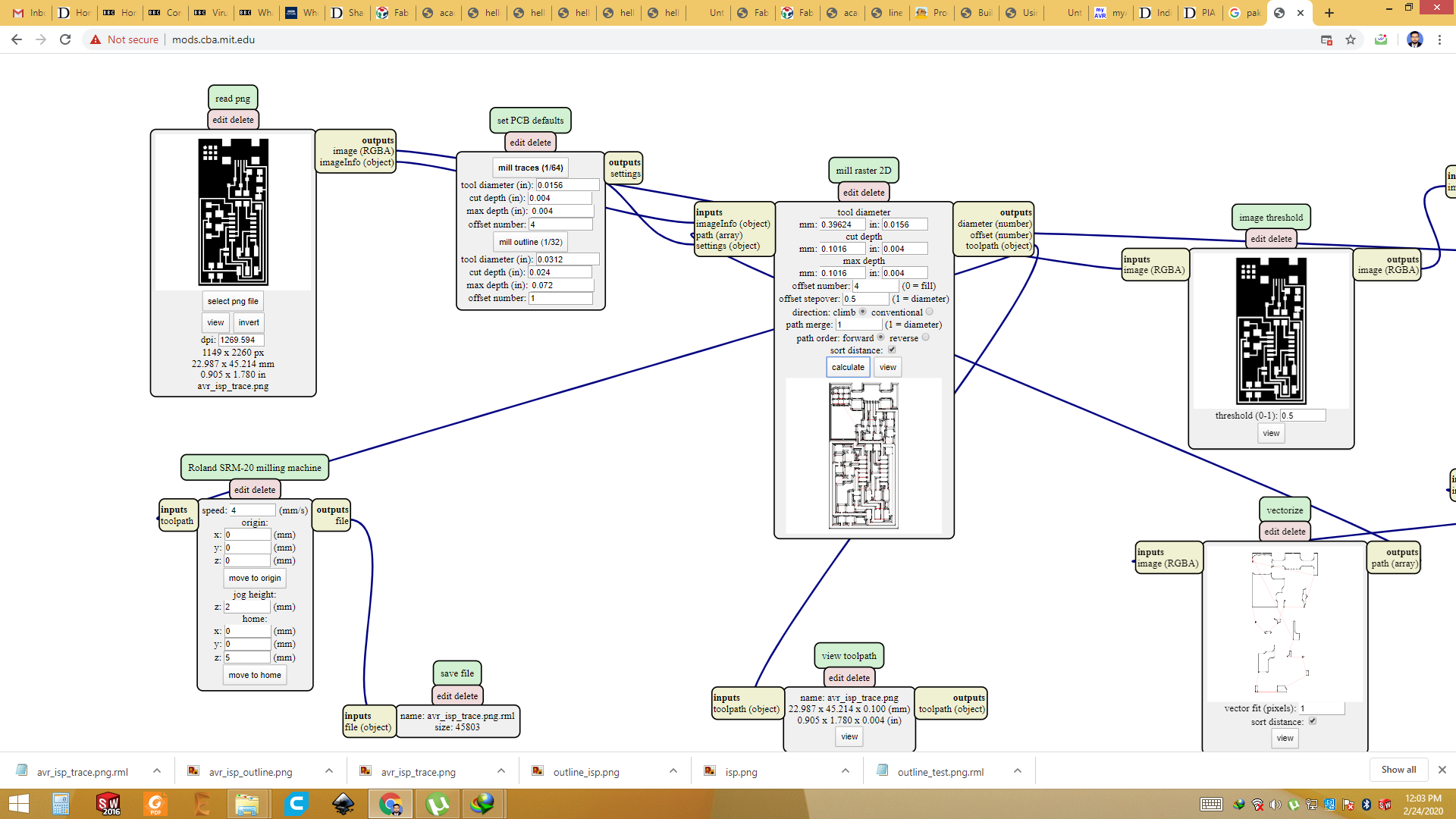
Step 5: Import PNG file from PC.
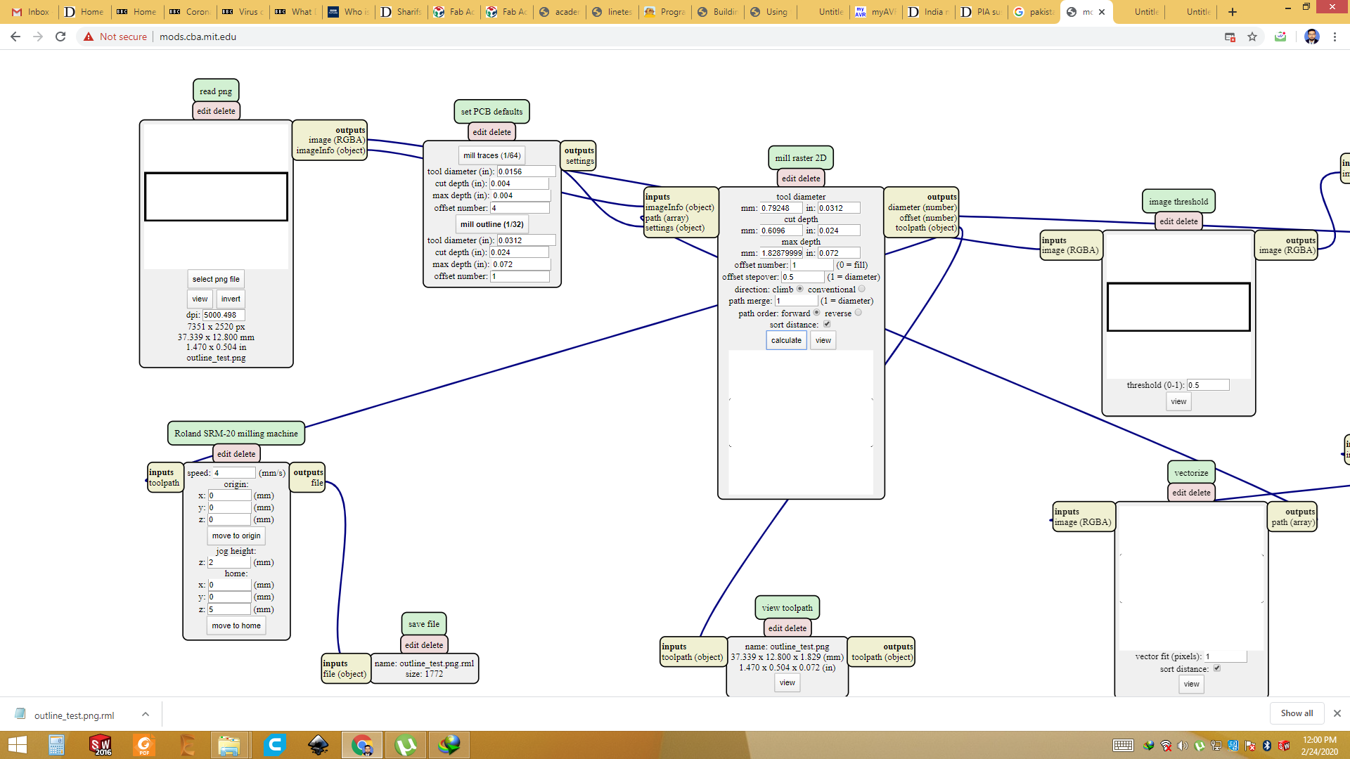
Click on "Select PNG file" and browse to png. Select and open it. Select the outline/trace. 1/32 for outline and 1/64 for the trace. Then click Calculate. Rml File will be automatically saved in your PC.
Step 6: Repeat step 5 for outline/drill
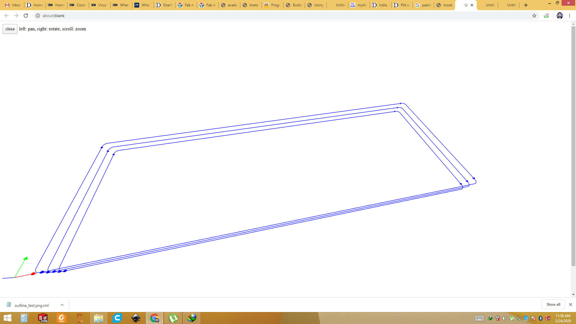
Step 7: Click on "view" to see the machine path ".
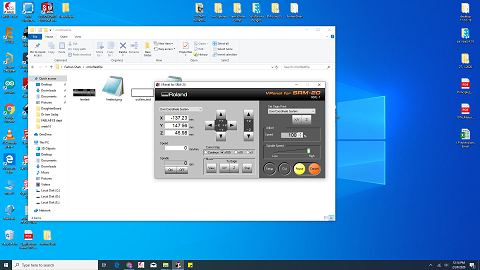
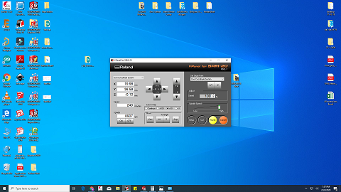
Step 8: Open Machine software"V Panel for SRM 20"
Set the start point manually. Save the X, Y and Z points. Click the cut and browse the rml file which we calculated using
mods and then click "output".
Note: Always cut the trace first with 1/64 bit.
Step 9: Change the tool(1/32 for outline)
After trace, change the tool and place the 1/32 bit. Adjust the Z axis again and click "cut".
Step 10: Take it out.
Clean it using Isopropile Alcohol.
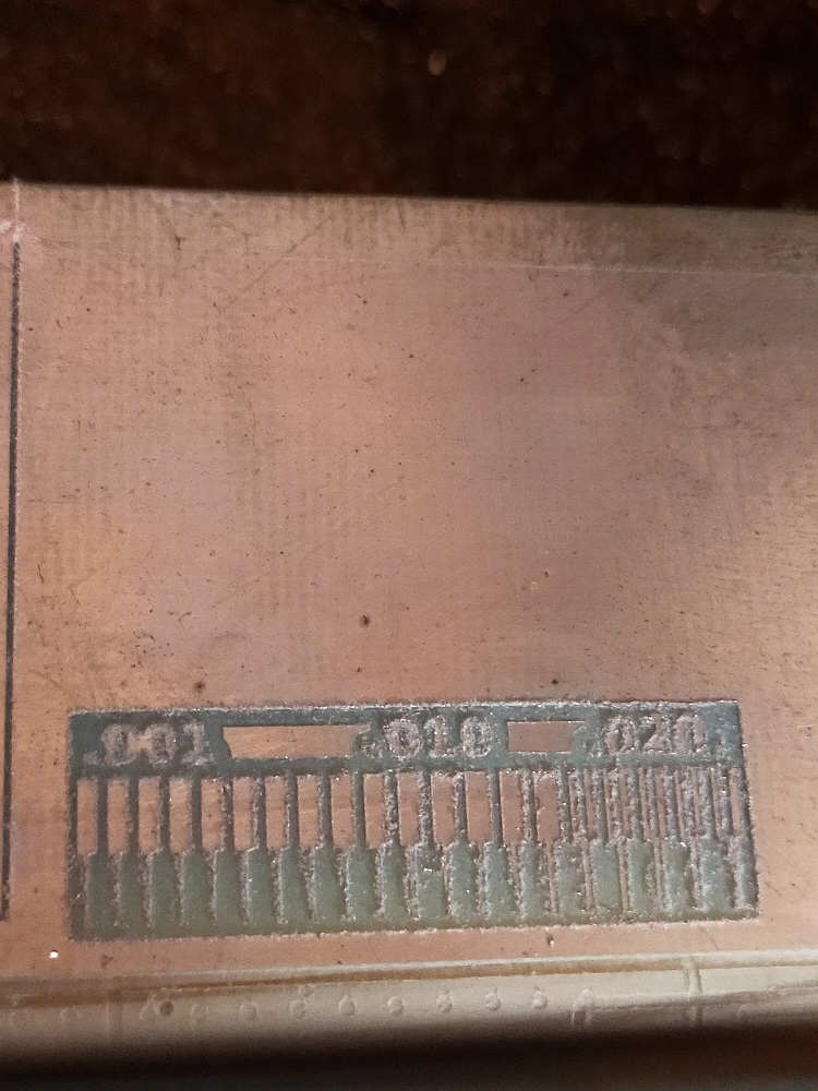
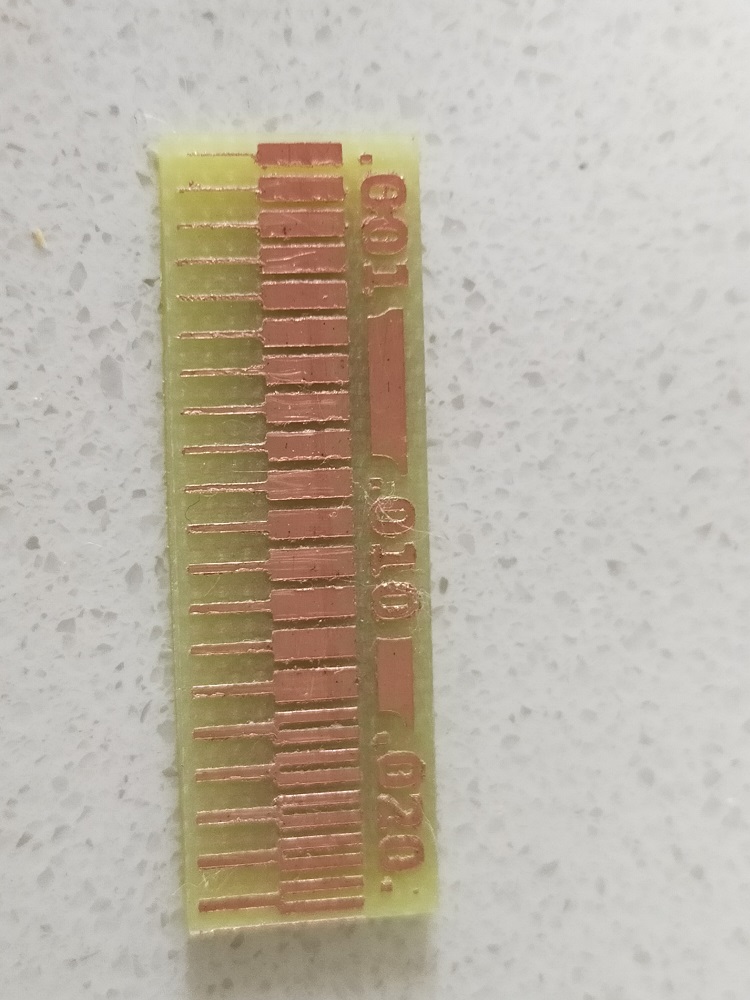
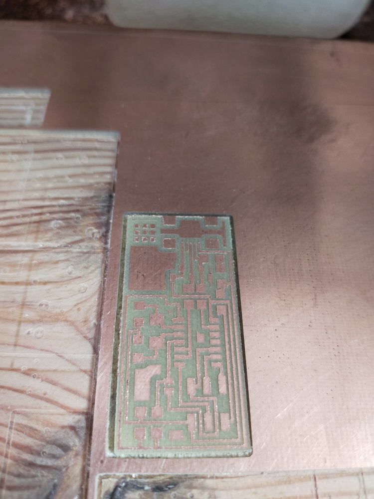
Final result
Bit was little old that's why you see result is not too good, but it is good enough.
Assignment: make an in-circuit programmer by milling and stuffing the PCB,test it
In this week we need to make the pcb of ISP, program and to test it. So I took Neil's circuit of AT tinny 44 from here. I took png file of trace and outlined and processed it using MODS to get the rml file. Gathered the components used it this circuit and soldered it. I tested circuit with multi-meter. Finally I programmed it using Linux operating system.
Step 1: Generate the rml file for traces.
Follow the above steps to generate the rml file.
Step 2: Generate the rml file for outline.
Use same process for outline. Select 1/32 bit size.
Step 3: Open the V panel for SRM 20 software
Set the X, Y and Z position of the machine where you want to start the cut. Then import the rml file generated through mods. First take the traces file and mill. After trace is complete, change the bit to 1/32 bit. Set the Z axis and then mill.
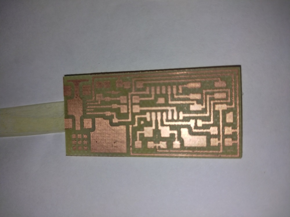
Step 4: Take it out and clean it.
Here is final result
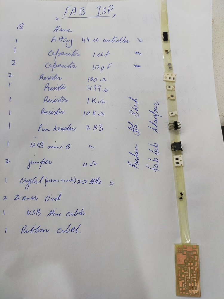
Step 5: Take out all the components
Best practice is to write all the components with values and put double sided tape on side of paper. Paste the component against each name and also put board there.
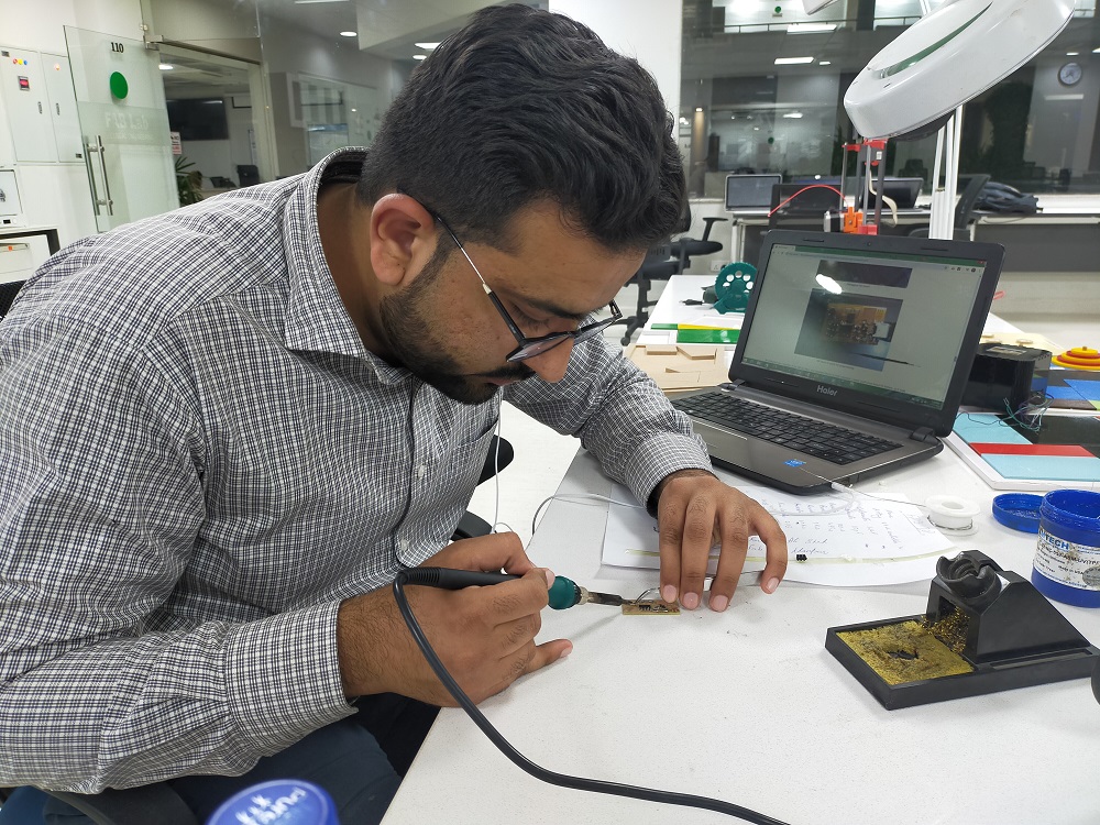
Step 6: Soldering
Open image and circuit board on PC or laptop in front of you and start soldering. Best practice is to solder the IC first then small components from center to outside direction.
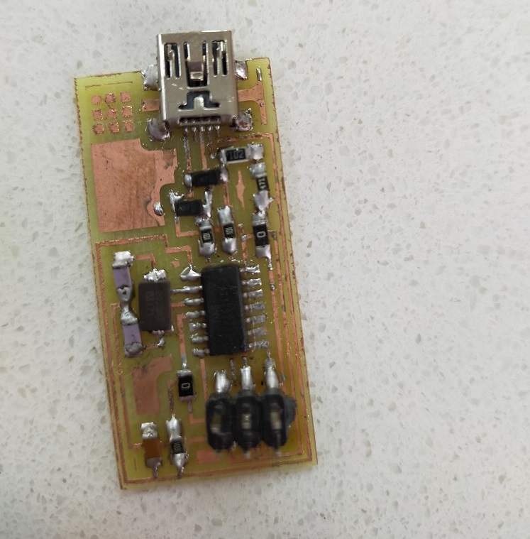
Final
Step 7: Programming
Before the start of programming, check all the connection using Multi-meter. Make sure that there is no any short circuit. For programming I followthis tutorial. I am using Linux to program using my instructor usbtinny isp. Following are steps:
- To program the Fab ISP, you first need to install the necessary software for your operating system and download the firmware.
- Edit the Makefile
- Set the fuses / program the board
- Verify that the board is working properly
- Then you need to open up the jumpers to make it a programmer.
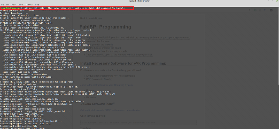
Ubuntu Software Install
Follow this tutorial
and Install necessary Softwares, downloaded the firmware and edit the make file
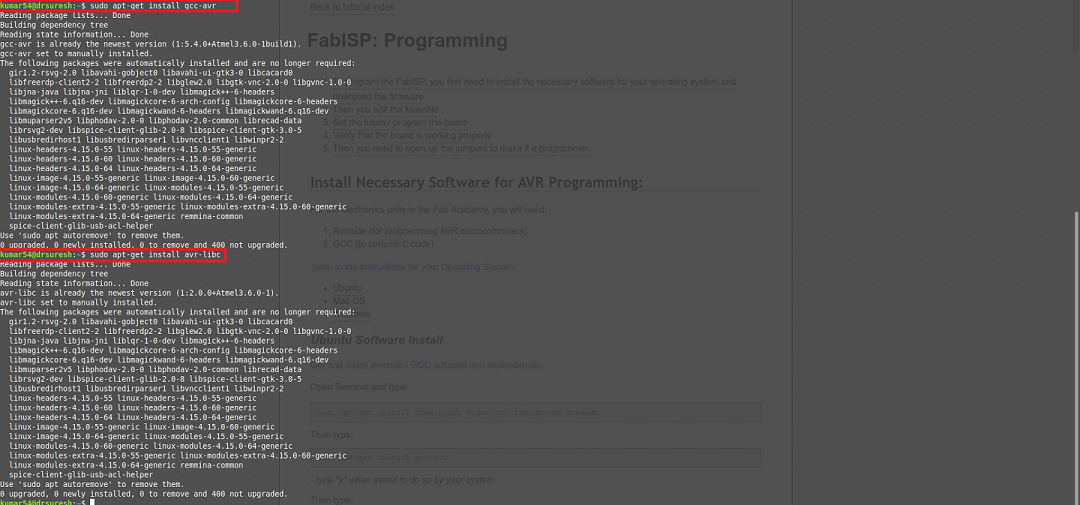
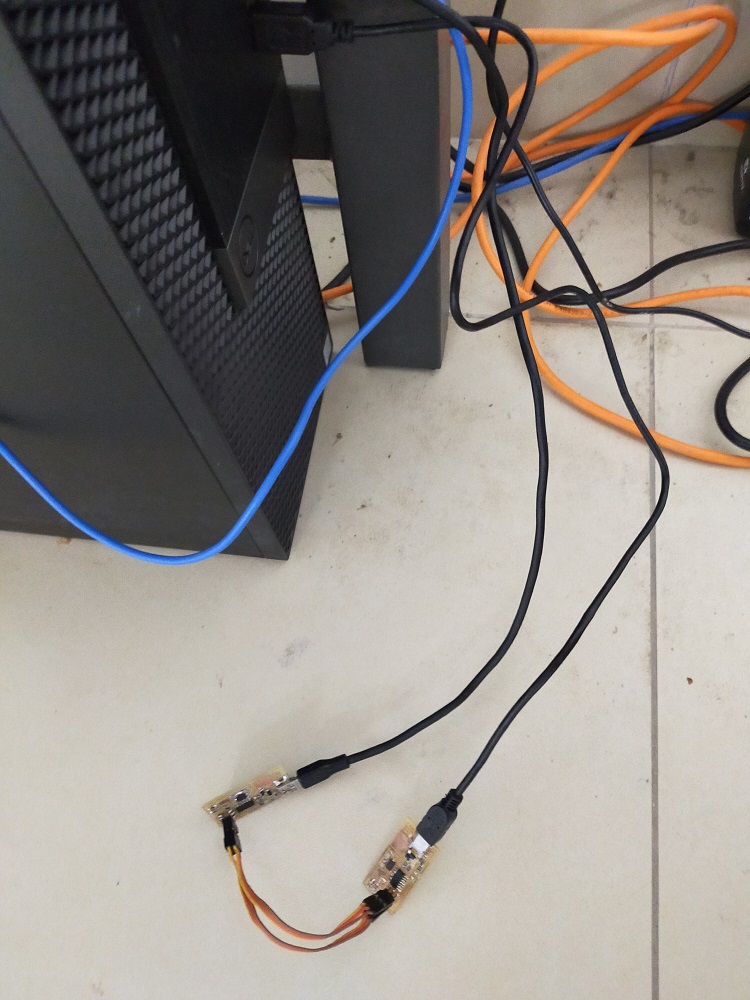
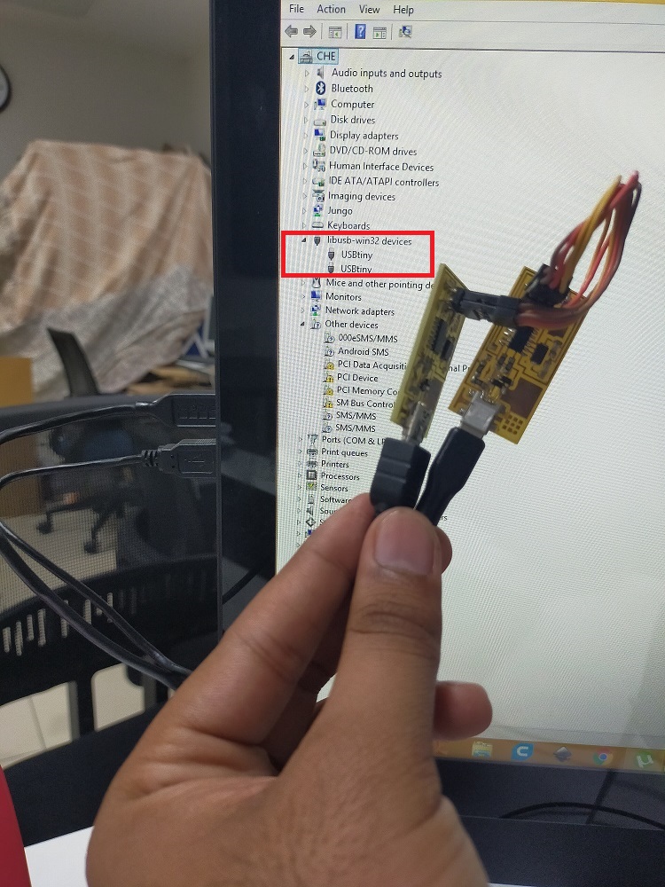
Connect my ISP with my instructors ISP and computer
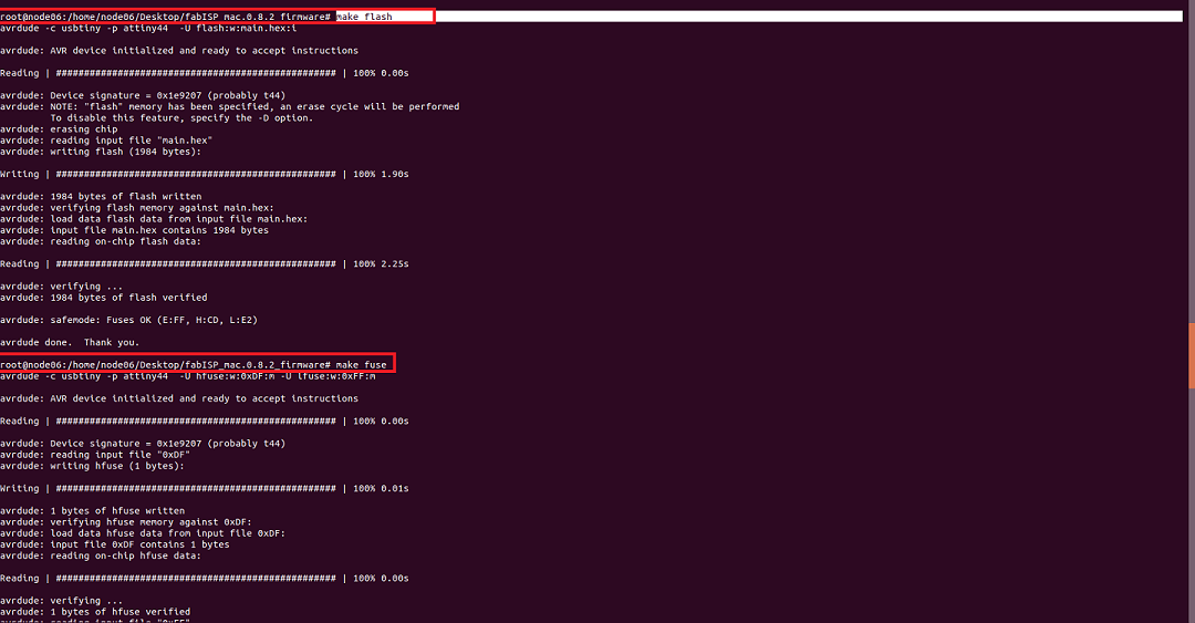
Run the command "Nano Makefile" ,"Make clean", "Make hex","Make Fuse" and "Make program"
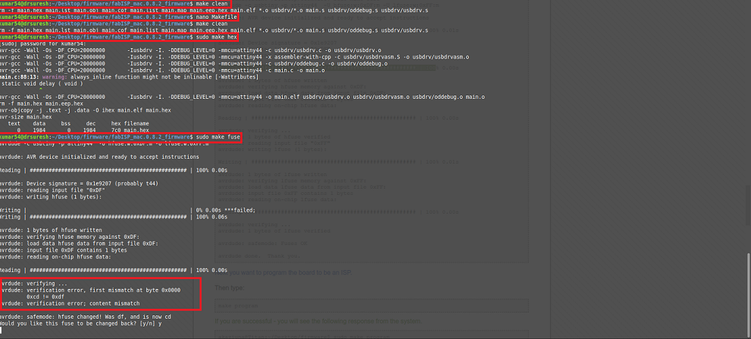
After hex was completed if tried to run the make fuse command but I got this error. I tried to debug it. Tested the connections, then tried but again I was getting same issue. After revisiting the above tutorial, I found my mistake. I didn't edit the make file. I opened make file and comment out this line.
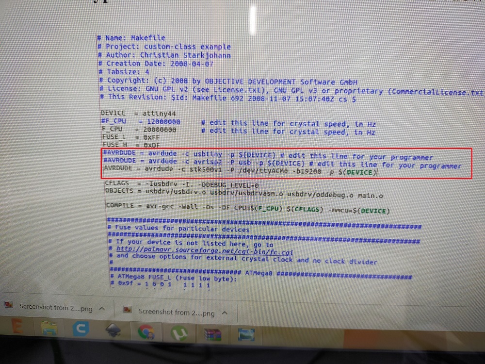
Re-run the command "Nano Makefile" "Make clean", "Make hex","Make Fuse" and "Make program"
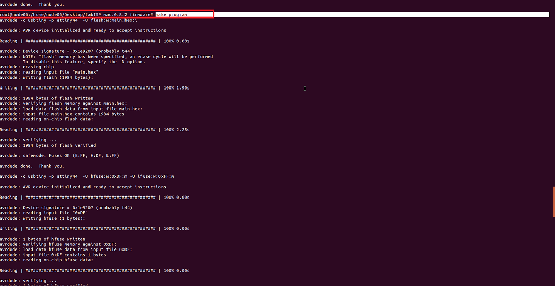
finally it worked.
Final result
Now desolder the 0-ohm resistor to make it a programmer
Download all files from here

This work is licensed under a Creative Commons Attribution-NonCommercial-ShareAlike 4.0 International License.