Kerf test
In this week we have to work on laser cutter, so first of all we need to characterize few things of our laser cutter.
Number one is Kerf. When laser burn the material, the thickness or area of material which burn away are called kerf. The area/thickness may vary.
Source:http://engineeringdiys.blogspot.com/
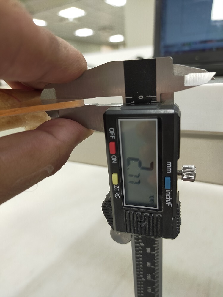
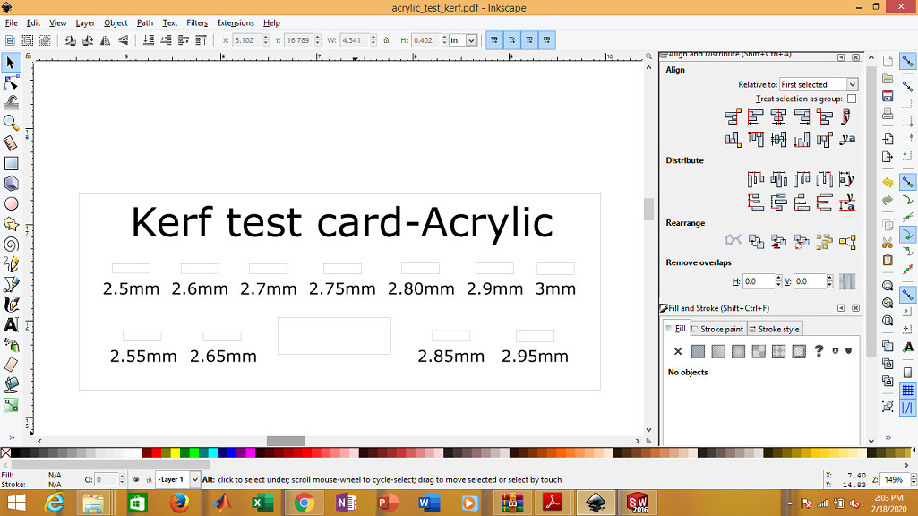
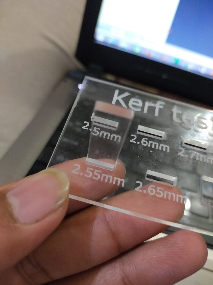
In order to measure the kerf of our laser cutter, I have designed test file in INKSPACE. Firstly I have measured the thickness of our
material then i have made rectangular boxes of different thickness with 0.05mm difference around the actual thickness of material. I have cut one
long slit of same height. Idea is to check which hole is perfect fit for that slit so that I can use that thickness.
Measuring the thickness
Working in Inkspace
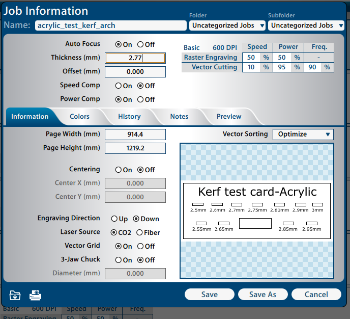
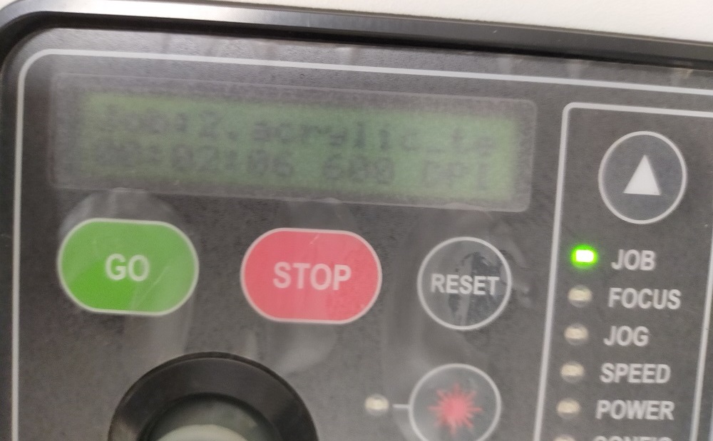
Setting in epiloger
reseting the machine
Testing kerf in different slots. 2.55mm suit best for 2.77-2.75mm
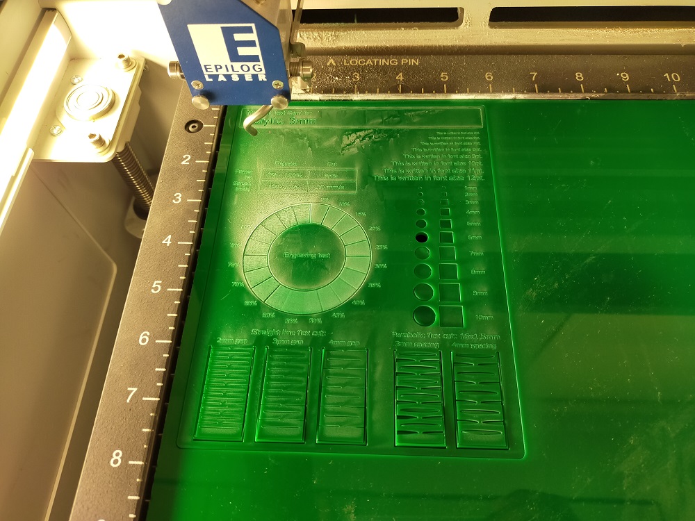
Test card for power,speed,focus,rate
Similarly in order to test the power, speed, focus and rate we took the test from here. Edited it and then processed through epilog and cut it. We can see from below test card that changing the shades can effect in engraving. The darker the shade, the more it will engrave. Also it show the hole size, flexible cut and engraved writing
Test card for lasercutter
Individual Assignment
Design, lasercut, and document a parametric construction kit, accounting for the lasercutter kerf,which can be assembled in multiple ways,
My idea for this week assignment is to make table-top Pen holder with name plate. Requirement for this week is that design should be parametric. I am working in Solid works from past couple of years so I choose Solid works for the design work. Solid works is parametric software and user friendly.
Parametric modeling
Parametric modeling is a modeling process with the ability to change the shape of model geometry as soon as the
dimension value is modified. Parametric modeling is implemented through the design computer programming code such as a script to define the
dimension and the shape of the model.
Parametric modeling is an approach to 3D CAD in which you capture design intent using features and constraints, and this allows users to automate
repetitive changes, such as those found in families of product parts.
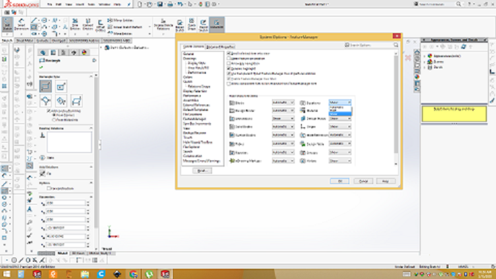
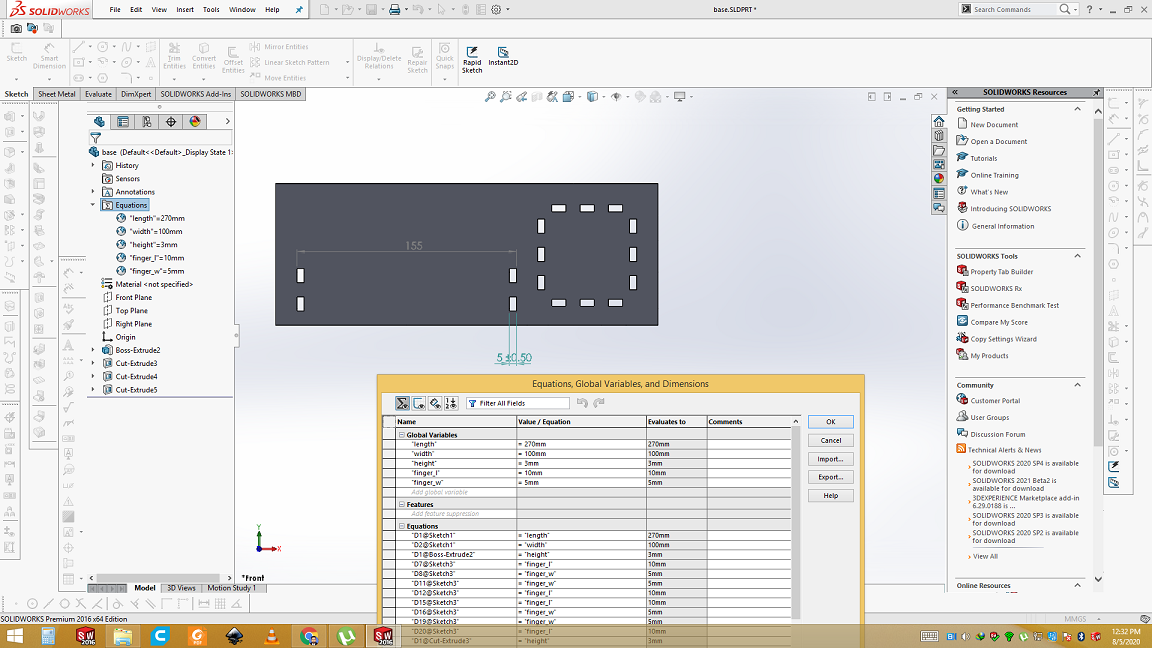
Enable the equation
To start working of parametric design in Solid work, first of all we need to enable the equation. Create variable of different name and assign them value. We can also assign them relations or any equation e.g length=width/2 where we only need to give value of with variable.
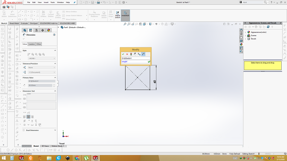
Start the drawing my dragging the 2D object and using the smart dimensions give them variable. In direct modeling we give direct number to side. But in parametric designing we assign variable in smart dimension by press ="variable". Whatever value we assign that variable in the equation box, that value will assigned to that side. It helps us in press fit design alot. If any thing goes wrong we don't need to draw all from begining. Just change the value in variable and model will be changed accordingly
Assigning the parametric dimensions
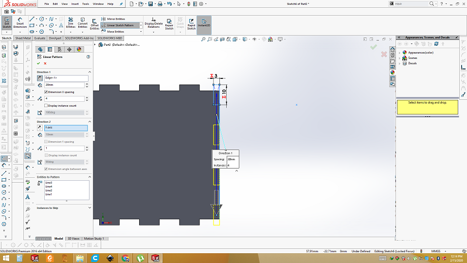
In order to press fit, we need negative and positive finger joints using linear sketch pattern.
Finger joints
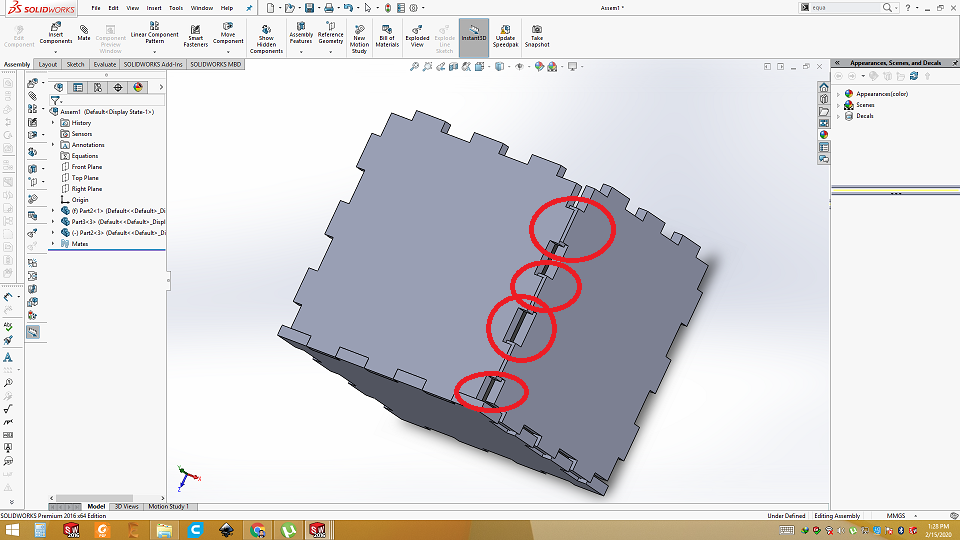
In press fit, you need positive and negative side to align. I have done mistake here.
Misalignment in design
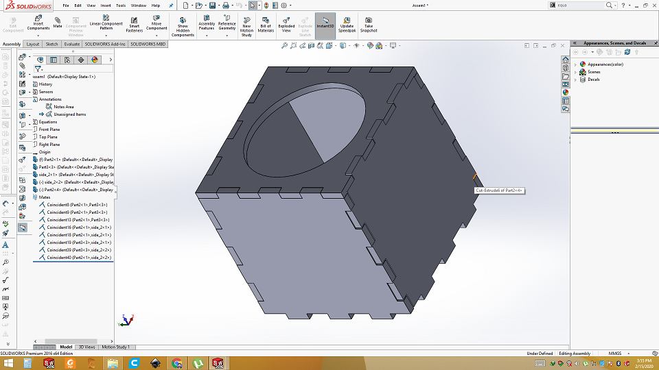
After few iterations, I am finally able to make pen holder box. I have made three different parts, two different sides and a separate top.
Box in Assembly
Then I made base, name plate, back plate and support
Base

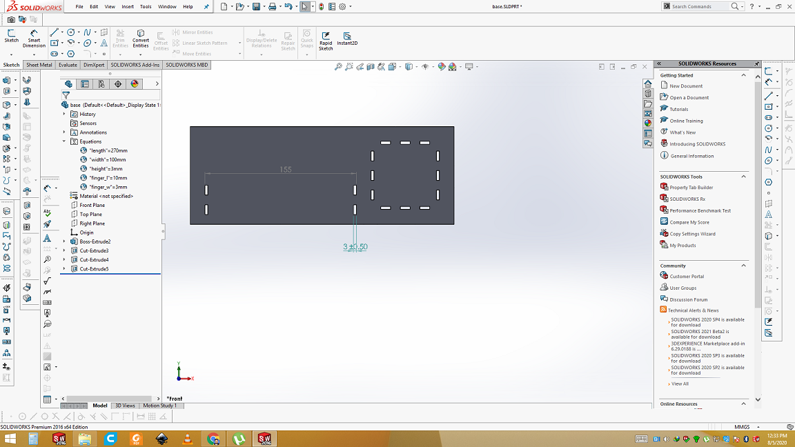
Changes with parametric modeling
As we have defined defined varibales and assign them into sides. Parametric modeling gives us ability to change any
parameter remeaning in 3D. If any time i found that holes of base is big or small so i can adjust them by just changing values in equation.
Open the equation. Now the width of the slit hole is 3mm and i want to make it 5mm. Just replace 3mm with 5mm and click ok. In run time you
will see the change in design. Everything else will remeain same.
here is the final assembly of Pen holder with name plate.
Assembly
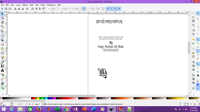
After that, we need to convert every part of solid works design into .dxf file. So, it can open in Inkscape Luckily solid works can save file in .dxf format. After saving in .DXF format Open all the parts in Inkscape. Put the text and embed the pictures (if any) into it. Let's process in Inkscape. In order to put picture on front of penholder I have used trace bit map. Then save as pdf.
Process in inkspace
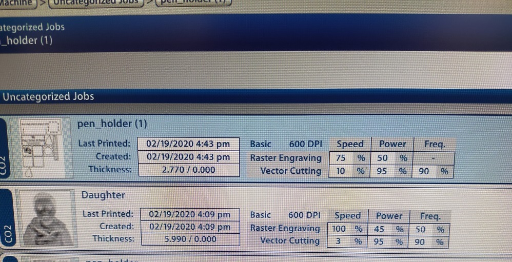
Then PDF file is given to Epilog for final process. Select the setting of laser and material like below.
Epiloger process
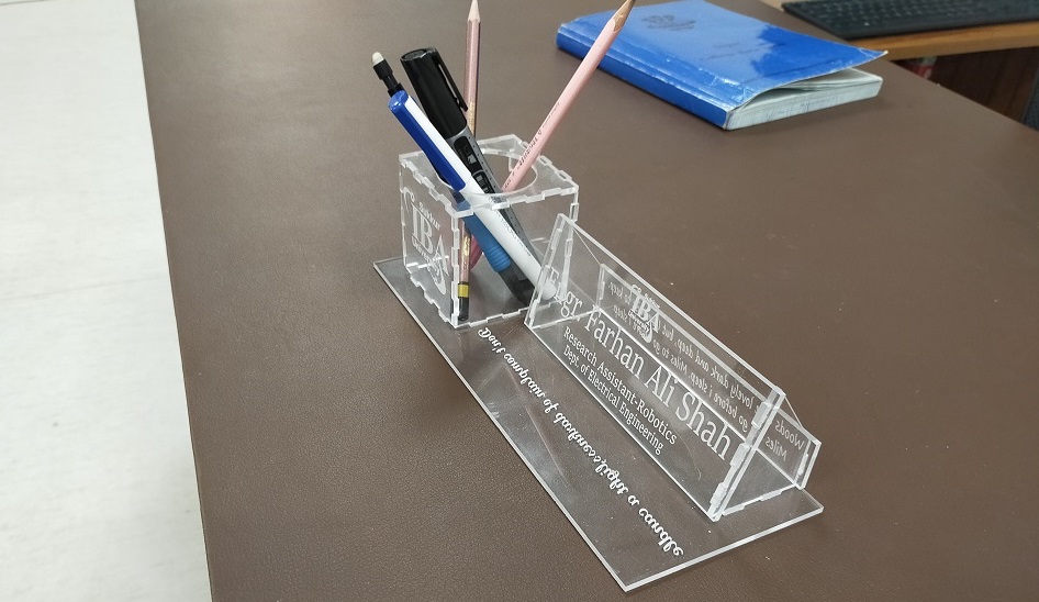
Assemble all the parts according to design.
Final result
Cut some thing on Vinylcutter
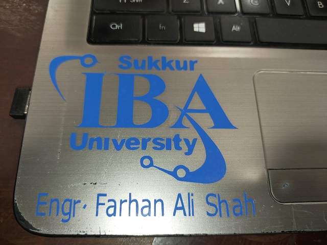
The second assignment of this week is to cut something on vinyl cutter. I have close bond with my university. I studied here, now i am working here. I also doing Fab diploma from Fablab khairpur which is part of my university. So I choose to cut the logo of my University along with my name.
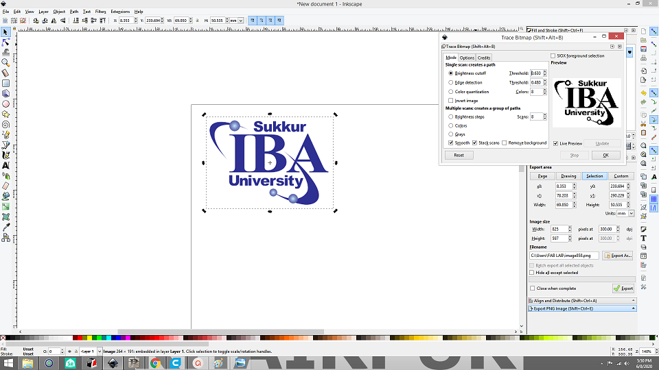
Open the inkscape software
First of all download the logo or any picture you want to cut on vinyl cutter. Open Inkscape software and import the logo. Go to "Path" and select the trace bit map. Select the brightness cutoff and adjust the threshold. Then remove the original picture and keep trace bit map logo.
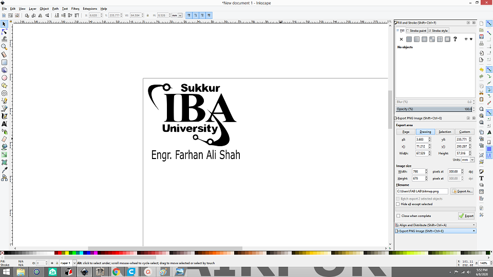
Add text
Add text like name or any text you want to cut, then save it as .PNG and then open .PNG file in Paint software and save as .BMP.
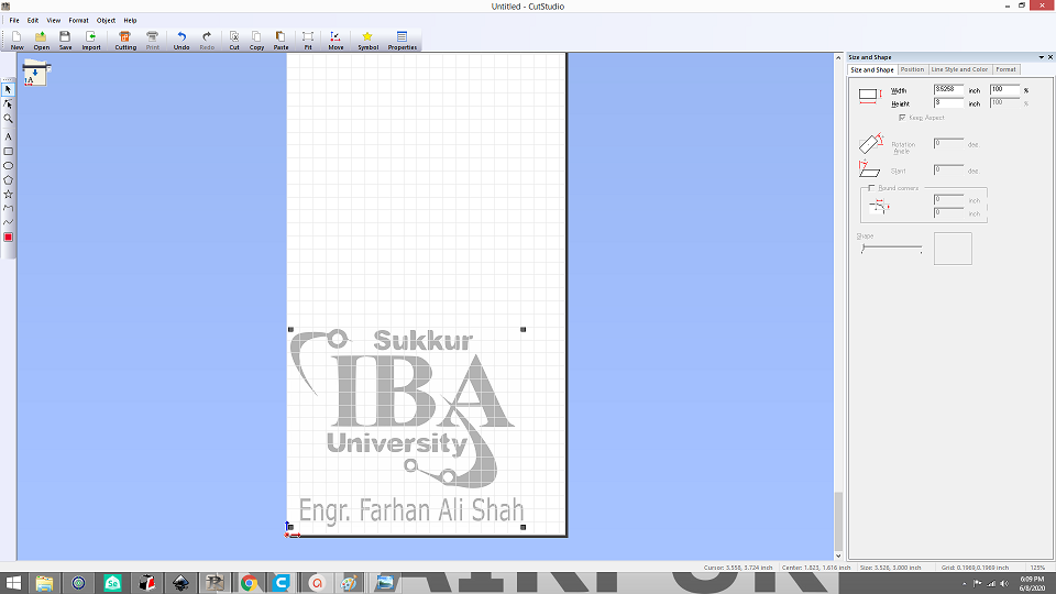
Open Cut studio softare
Now open cut studio software and import the .BMP file. Place it on corner of the sheet.
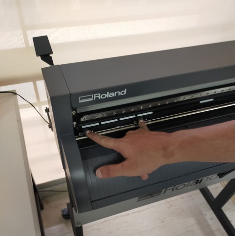
Sheet insertion
Sheet can be inserted from behind and these two rollers are there to fix the sheet. Important thing here is that roller can only be placed on these white markers.
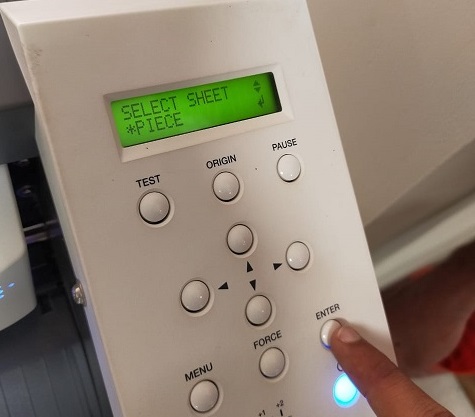
Sheet setting
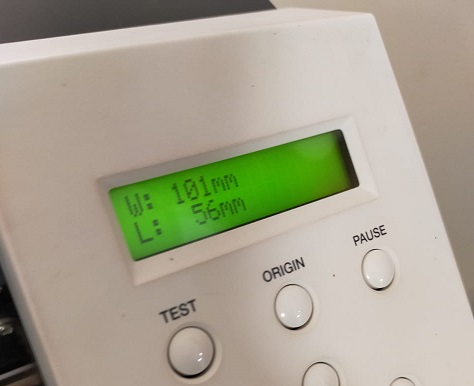
Open the Roland machine and select the sheet. If you are using piece of vinyl, then select the piece. Then click enter. Head will move and will give you dimensions.
Cut
Then go to software and select cut. Vinyl-cutter will cut on piece of vinyl. Then you have to remove the unwanted parts.
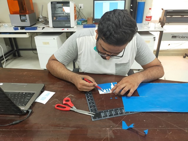
After removing unwanted part
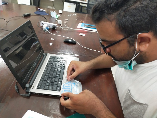
Here is result after removing unwanted parts. To paste it on any surface we need transfer paper. Take a part of transfer paper and paste on top of it.

Paste sticker using transfer paper
Now gently take out transfer paper. Now our striker is on transfer paper. Then paste your transfer paper on surface where you want to put your sticker.
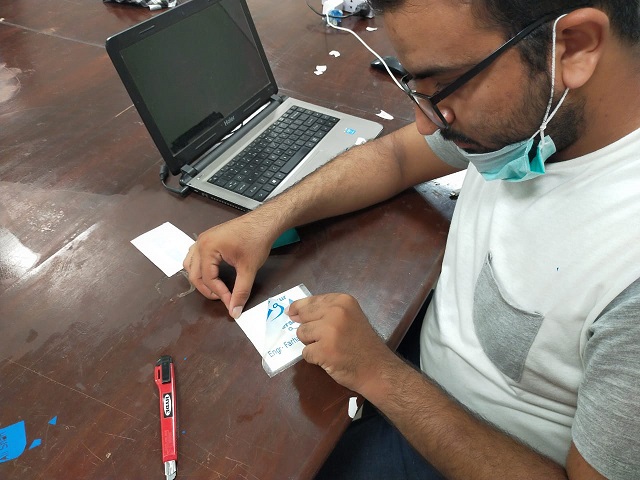
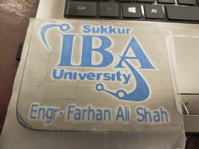
Pasted sticker
Press the sticker with card. Then gently remove the transfer paper so that sticker remains on surface and only remove the transfer paper.
Final result
Download all files from here

This work is licensed under a Creative Commons Attribution-NonCommercial-ShareAlike 4.0 International License.