Raster
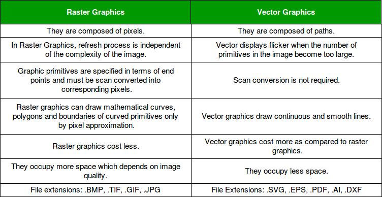
Raster images use bit maps to store information. This means a large file needs a large bitmap. The larger the image, the more disk space the image file will take
up. As an example, a 640 x 480 image requires information to be stored for 307,200 pixels, while a 3072 x 2048 image (from a 6.3 Megapixel digital
camera) needs to store information for a whopping 6,291,456 pixels.
File extensions: .BMP, .TIF, .GIF, .JPG
vector
Making use of sequential commands or mathematical statements or programs
which place lines or shapes in a 2-D or 3-D environment is referred to as Vector Graphics. Vector graphics are best for
printing since it is composed of a series of mathematical curves. As a result vector graphics print crisply
even when they are enlarged. In vector graphics, the file is created and saved as a sequence of vector statements.
Rather than having a bit in the file for each bit of line drawing we use commands which describe series of points
to be connected.AS a result a much smaller file is obtained.
File extensions: .SVG, .EPS, .PDF, .AI, .DXF
Raster vs Vector

Paint
First of all, I am window user so for raster i went to use the Paint software.
Microsoft Paint is a simple raster graphics editor that has been included with all versions of Microsoft Windows. The program opens and saves
files in Windows bitmap, JPEG, GIF, PNG, and single-page TIFF formats. The program can be in color mode or two-color black-and-white, but there
is no grayscale mode.
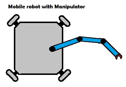
I tried to draw the robot of base with robotic arm. However, paint is very basic and limited in features. I just to mange draw
like this.

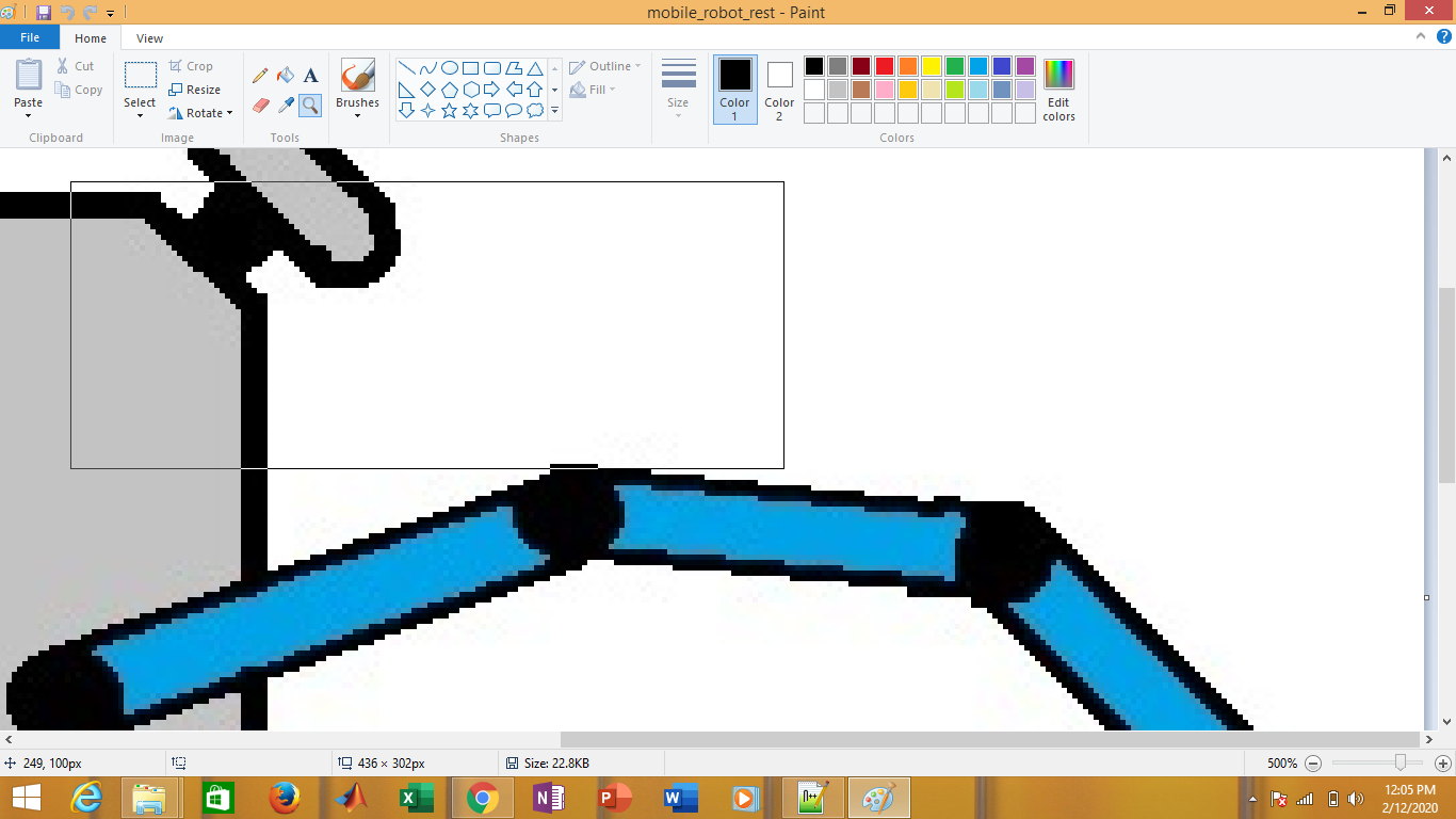
you can clearly see that picture is made up of pixels.
Drawing in Paint

Inkscape
Inkscape is a free and open-source vector graphics editor used to create vector images, primarily in Scalable Vector
Graphics format. Other formats can be imported and exported. Inkscape can render primitive vector shapes and text.
I tried to make the
key chain with my name in the inscape.
Open Inkscape and form any shape
First of all open the inscape and select the A4 page size. Then click on shapes and draw the rectangular box. Measure the both sizes and adjust accordingly. For hole, pick the circle and draw the circle. Pick the texting tool and write the name/what you want to write.


Key chain with name


Circle area shows that it is made of paths not pixels.
3D desiging
There are two types of software or work flow of 3D desiging.
1. Non Parametric 3D softwares
2. Parametric 3D software.
There are also software in which we can work on parametric as well as non parametric 3D designing.
Non-Parametric 3D designing
Nonparametric modelling involves a direct approach to building 3D models without having to work with provided parameters. Therefore, you will not be required to start with a 2D draft and produce a 3D model by adding different entities. This means you directly model your ideas without working with pre-set constraints. That is also why nonparametric modelling is also known as direct modelling.
SketchUp
SketchUp is a 3D modeling computer program for a wide range of drawing applications such as architectural, interior design, landscape architecture, civil and mechanical engineering, film and video game design.
3D designing in SketchUp
I am very new to this software. So i decide to make very simple 3D design in SketchUp. I want to make cubic box open from top and it has circular and rectangle openings from sides. First open the sketchup and draw the rectangle. In the bottom right corner, dimension box is avaible. You can give dimensions directly using this box. Give dimension to the reactangle box then extrude it. Click on offset and draw a reactangle with offset of 1/4inch and extrude.


Draw reactangle on the side and using the extrude move button drag it to the back and delet that portion. Similarly draw the circle and
extrude and move the portion and delete it.


Here is final result

Parametric 3D designing
Parametric design is a process based on algorithmic thinking that enables the expression of parameters and rules that, together, define, encode and clarify the relationship between design intent and design response.There are many parametric software but i like to use Solid works.
Solid works
SolidWorks is a solid modeling computer-aided design and computer-aided engineering computer program that runs primarily on Microsoft Windows. While it is possible to run SolidWorks on MacOS, it is not supported by SolidWorks. SolidWorks is published by Dassault Systèmes. Let's start making base of the key chain.
Open Solidworks and draw the rectangle
Open the solidworks and draw a rectangle. Right click on the equation and select the manage the equations. Write the name of variable in "Global variable" box and assign value or equation/relationship in the "Value/Equation" column. I have given the length,width, height variable. Length is independent variable where as width is half of length and heigth is 10th of the width. Click ok. Now select the smart dimension and click on any side. press "=" sign and variable that we have made is visible now. Select the desired variable. First length and then width.


Extrude and assign height
Click on extrude and put "=" and select the "height" variable. It will extrude.

Create hole
Select the face of cube and click on sktech. Draw a circle and assign it hole variable which is equal to height variable. Then extrude cut it through all.


How parametric work
Now we see the power of parametric design. 3D model is built. It is very easy to change the parameter or size of 3D object in parametric design. Width is fuction of length, height is the fuction of width ans so on. By changing only value, every side will be change but relationship will remain same. Length was 100mm now i am changing it to 90mm.

After changing one value
Now see length is 90mm which automatically changed the width to 45mm which is half as described in equation. hole is 4.5mm as well as height. Every variable was connected with each other so changing length variable results in changing all the values thus relationship is same.

Download all files from here

This work is licensed under a Creative Commons Attribution-NonCommercial-ShareAlike 4.0 International License.
