Group Assignment
In this week, in group assignment we are working on the I2C communication between two micro controllers, one is Arduino mega 2560 and other is Leonardo Board. We have fellow this this link to implement group assignment. HERE
What is I2C?
The I2C communication bus is very popular and broadly used by many electronic devices because it can be easily implemented in many electronic designs which require communication between a master and multiple slave devices or even multiple master devices. The easy implementations comes with the fact that only two wires are required for communication between up to almost 128 (112) devices when using 7 bits addressing and up to almost 1024 (1008) devices when using 10 bits addressing.
Each I2C bus can support up to 112 devices. All devices need to share GND. The speed is around 100 kb/s—not very fast but still respectable and quite useable. It is possible to have more than one master on a bus, but it's really complicated and generally avoided. A lot of sensors use I2C to communicate, typically Inertial Measurement Units, barometers, temperature sensors, and some Sonars. Remember that I2C is not designed for long cable lengths. Depending on the cable type used, 2 m might already cause problems. Connecting more devices If we need to connect more than two devices on an I2C bus, we just have to connect all SDA and SCL lines together. We will need the address of every slave to be addressed from the master Arduino.
ADVANTAGES
DISADVANTAGES
We have connected micro controller, so these steps to connect two Arduinos using I2C:
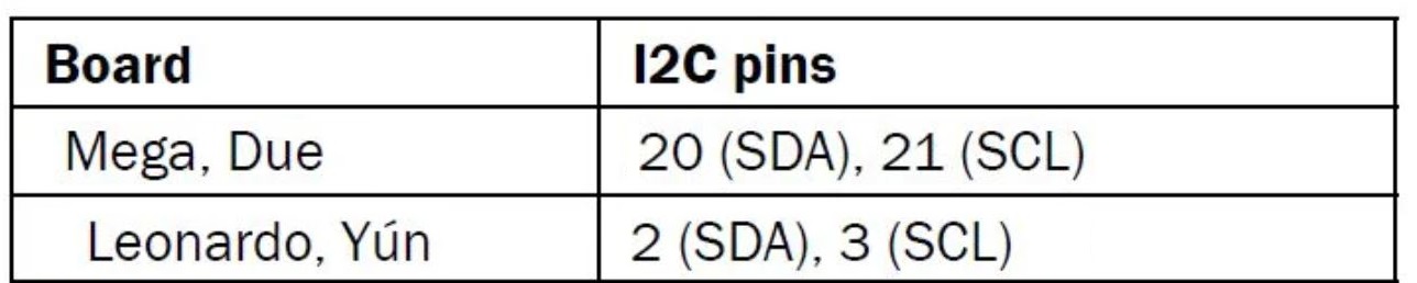
First step Connect pin A4 and pin A5 on one Arduino to At mega 25600 pin 20 SDA , and pin 21 SCL . Second Step the GND line must be common for both Arduinos. Connect it with a jumper. Third Step Remember never to connect 5 V and 3.3 V Arduinos together. It won't hurt the 5V Arduino, but it will certainly annoy its 3.3 V.
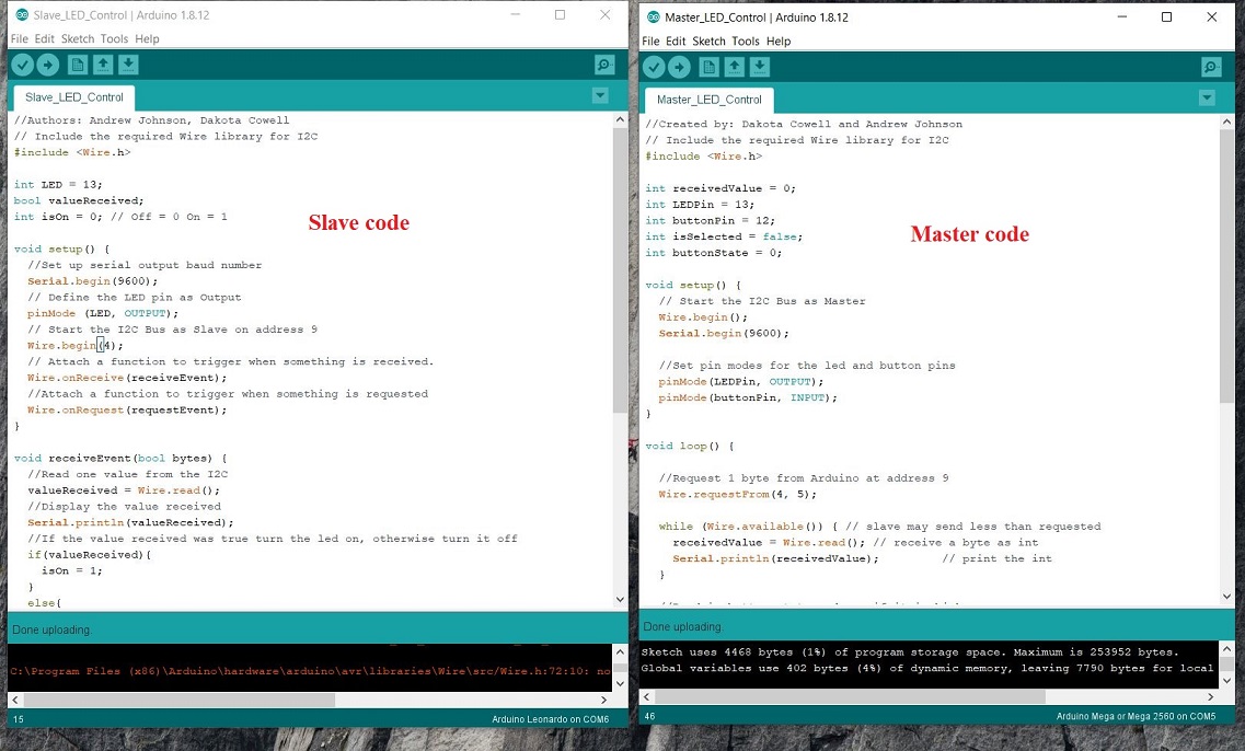
This is the code of master and slave; that is used for the communication I have uploaded the code like master in mega2560 and Salve upload Leonardo.
How It Work
To briefly go through the theory, I2C requires two digital lines: Serial Data Line (SDA) to transfer data and Serial Clock Line (SCL) to keep the clock. Each I2C connection can have one master and multiple slaves. A master can write to slaves and request the slaves to give data, but no slave can directly write to the master or to another slave. Every slave has a unique address on the bus, and the master needs to know the addresses of each slave it wants to access. Now let's go through the code.
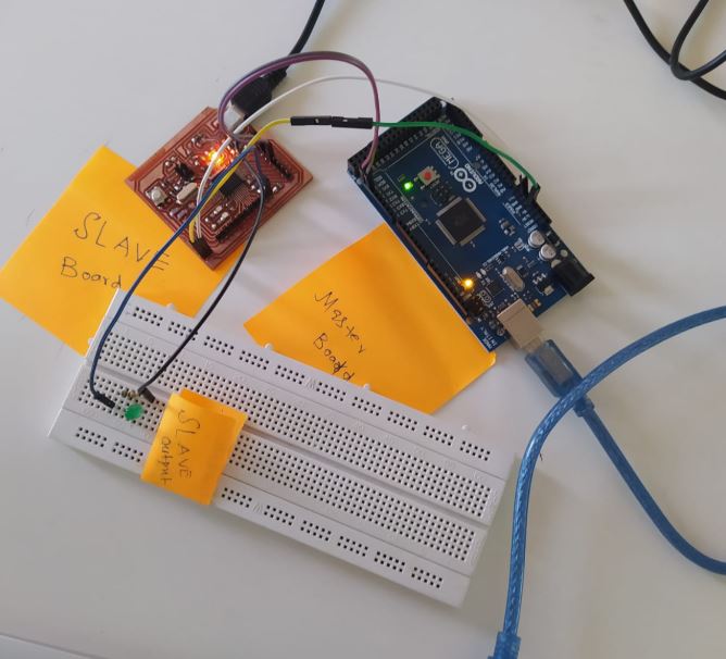
After the uploading the code in the respective board this is the result of our Group assignment in which master sent the command to the slave.bascialy in this assignment, we have considered one microcontroller board as a master board that will command on the other board that is a slave when I am going to press the button of the master board that will start blinking one time and sent the command to slave board for the blinking lED.even we have connected extra led on pin 13 for the blink that shows the communication between master and slave board.
Assignment:
Design, build and connect wired or wireless node with network or Bus addressess
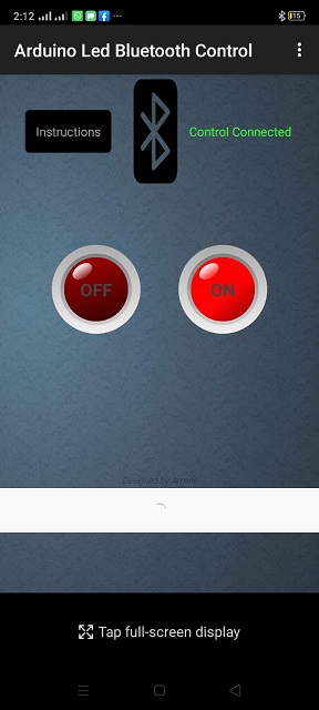
In this week my goal is to control the LED on microcontroller board via bluetooh. In my final project i want to use bluetooth to controll my mobile robot. I will make my own app for final project with some addiontional command. For this week i downloaded the app called Arduino Led bluetooth controllapp from play store. This app has two button, On and Off. By pressing On button, app send "1" and by pressing OFF button this will send "0".
Ardiod App
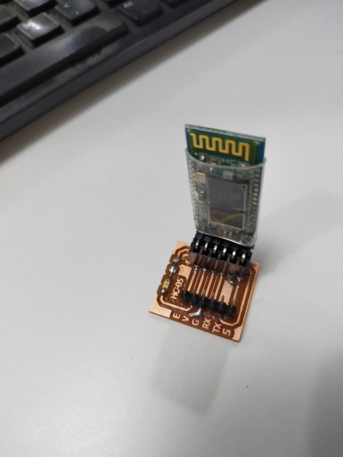
In hardware, i am using HC-05 bluetooth module.
Ardiod App
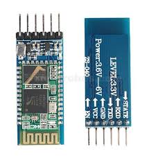
HC-05 module is an easy to use Bluetooth SPP (Serial Port Protocol) module,designed for transparent wireless serial
connection setup. The HC-05 Bluetooth Module can be used in a Master or Slave configuration, making it a great solution for wireless communication.This
serial port bluetooth module is fully qualified Bluetooth V2.0+EDR (Enhanced Data Rate) 3Mbps Modulation with complete 2.4GHz radio transceiver and
baseband. It uses CSR Bluecore 04‐External single chip Rluetooth system with CMOS technology and with AFH (Adaptive Frequency Hopping Feature).
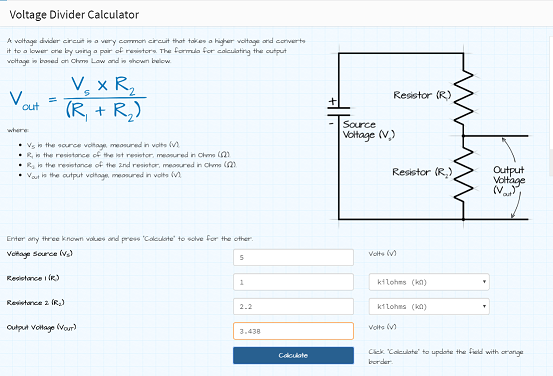
As you can see that RX pin of the HC-05 can only take 3.3v. Digital pin of microcontroller gives 5V output. I made PCB in which
i added voltage divider circuit.
Calculation for volatage divider
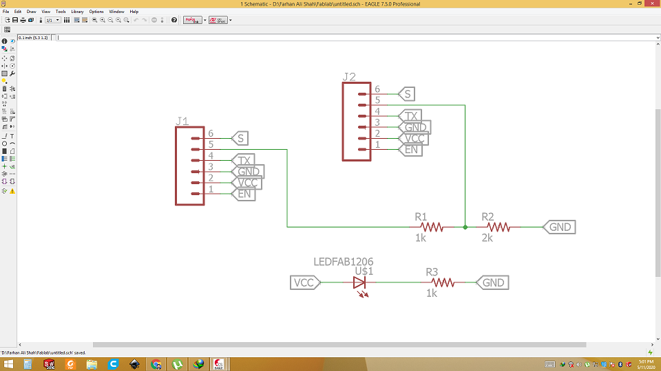
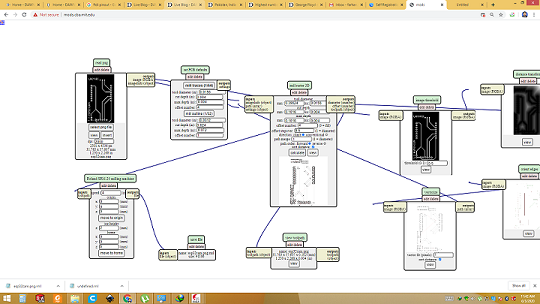
After the calcuation i start working in Eagle for PCB.
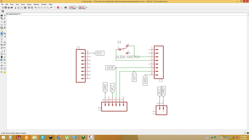
Schematic design
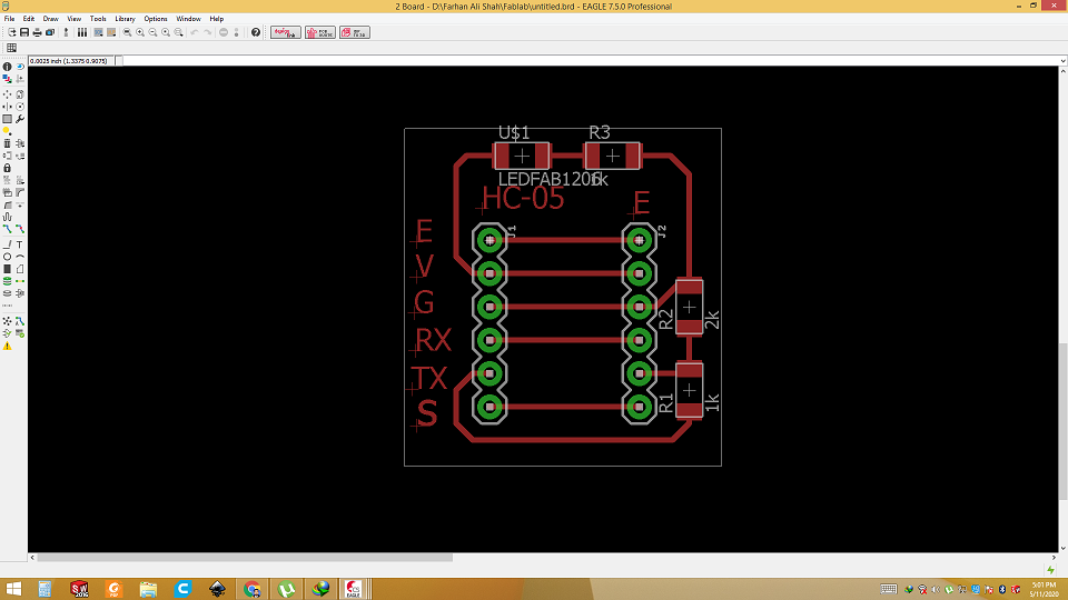
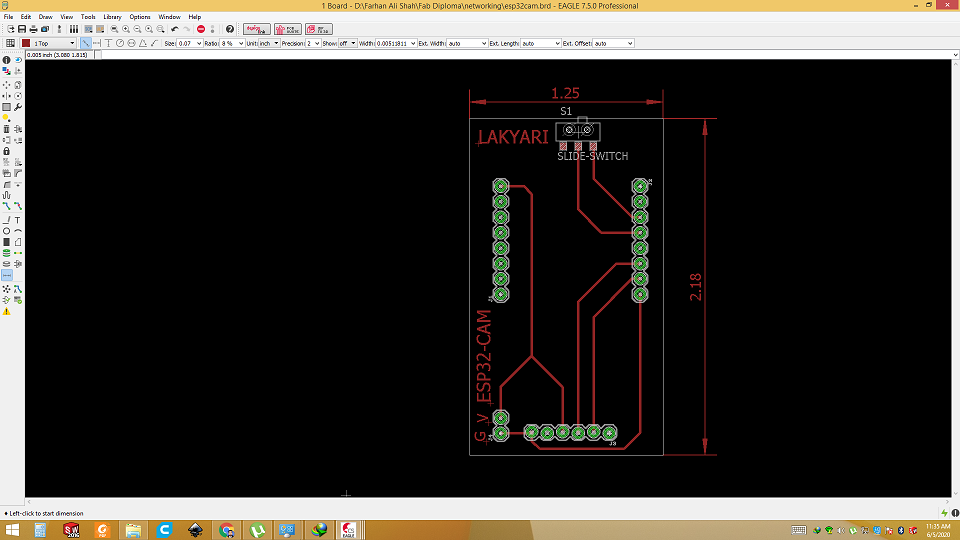
board layout
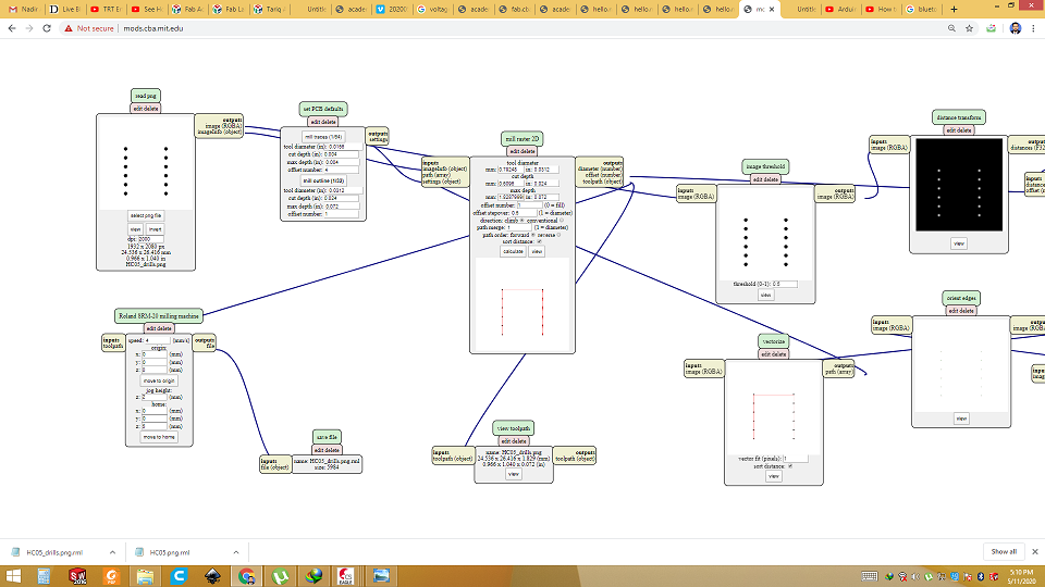
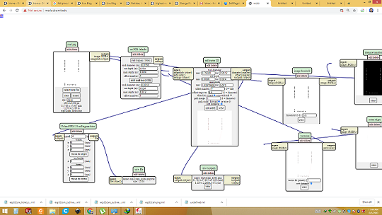
Generating RML
Milling
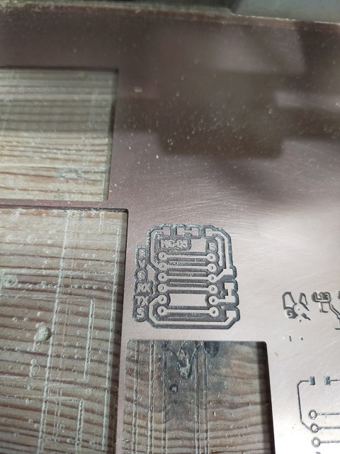
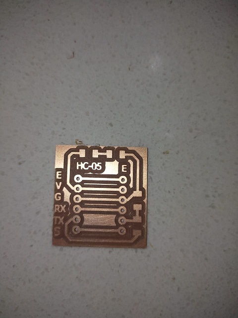
Milled
Components popualted
Test using Arduino
Final Test using Atmega32U4 board
Due to lockdown i was unable to mill the board for Embeded programming during that week. But now we got partial access of lab so i made the board of Atmega 32U4 breakout board for Embeded programming week. I am using that board with HC-05 for this week. In this video you can see the working...
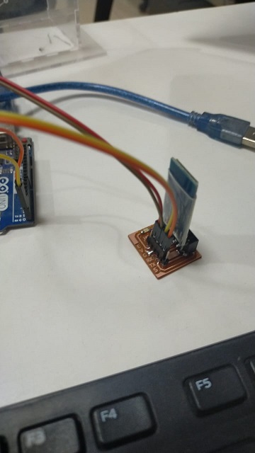
ESP 32-Cam for live video streaming
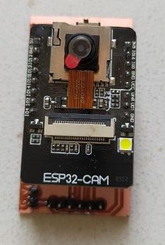
In this week, i have done one more thing which is part of my final project. I have used ESP 32-cam module for video transmission. In my final project, camera will be used to transmit the live video from mobile robot to mobile/PC. I took inspriration from Neil's ESP 32 cam hello board and designed my own board for ESP32-cam. This board will help user to easily program the ESP32-cam and also used to provide power to board when it transmit live video.
The ESP32-CAM: is a very small camera module with the ESP32-S chip that costs approximately $10. Besides the OV2640 camera, and several GPIOs to connect peripherals, it also features a microSD card slot that can be useful to store images taken with the camera or to store files to serve to clients.
PCB designing
Open schemtic design and import all the components. Make connections. then go to board layout and measure the distance between two lines of female connectors. That size should be same as of ESP32-CAM. Then route all the wires.
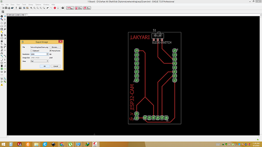
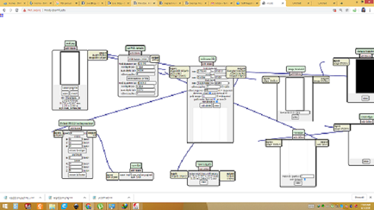
Save as .png and generate RML file
After design work is completed, go to file and export image as .png with 2000 dpi and monochrome. Then open that file in paint software and seprate the outline, hole and trace. Then open the mods and process all three file separate and generate RML file.
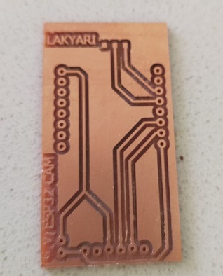
PCB milled
After generating RML files, we gave trace file first to machine. Then holes and finally outline file. After milling and soldering we got this result.
Programming
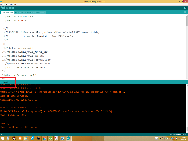
After hardware is setup correctly it is time for programming. Connect ESP32-CAM with computer via FTDI cable. Open examples and go to esp32 cam and select the camera. Comment and uncomment line as show in picture. Replace the wifi router credentials with your wifi router. Select the port and board. Then click upload.
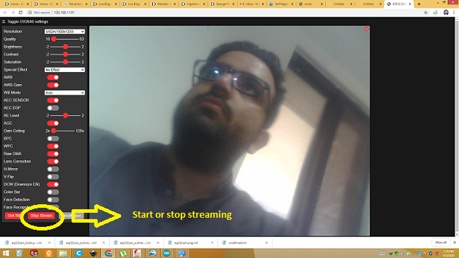
Video Streaming
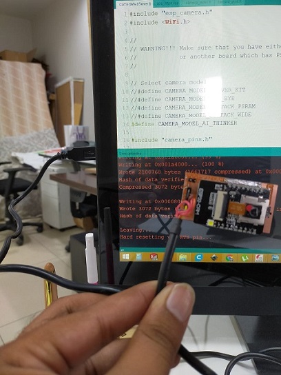
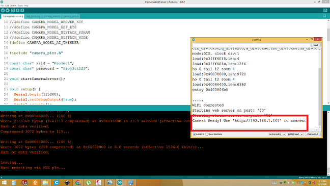
After done uploading open the serial monitor and hit the built in reset button. IP address will will appear on serial monitor. Copy that address and past it on your web brower. hit enter and page will open. Click on start streaming will start live video from ESP32-CAM. Video is attached for step by step guidance.
How to program ESP32-CAM
It is step by step video made my me on how to program esp 32-cam.
Download all files from here

This work is licensed under a Creative Commons Attribution-NonCommercial-ShareAlike 4.0 International License.