Project
Final Project
Outline design (ver 1.1), Joint
The outline design that I've done as ver 1.0 in week2(CAD) and week3(Computer-controlled cutting) was for initial idea that covers how I make outlike overall. I needed to re-think about:
- Re-design Pot outline in terms of size as an instrument and making a screw halls. Checked Rpi wide angle Camera focus point and keep relevant area on top acrylic table.
- Joint to construct and fix the shape of Pot
- The way to attache input devices (6 potentiometers and 4 switches) and output device(OLED)
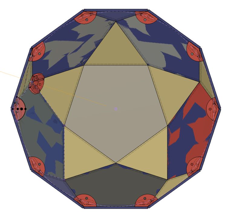
Re-design Pot outline
Basically the way to design is the same as outline design ver 1.0. I changed:
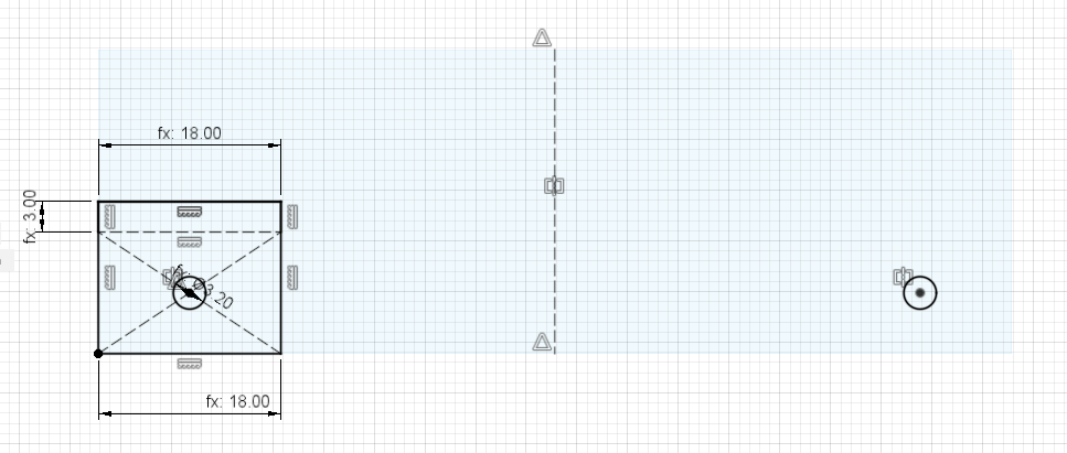
- The length of edge of the polygons(pentagon, triangle and the width of rectangle) : 90mm
- The height of top rectangle : 30mm
- Made screw halls of M3(3mm) for every vertex of polygon
3D model - PoTone_3DOutline_components (Autodesk A360)
Joint to construct and fix the shape of Pot
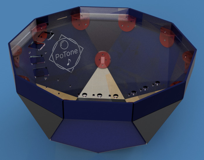
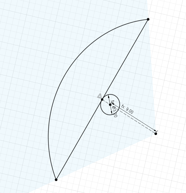
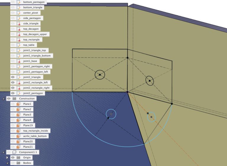
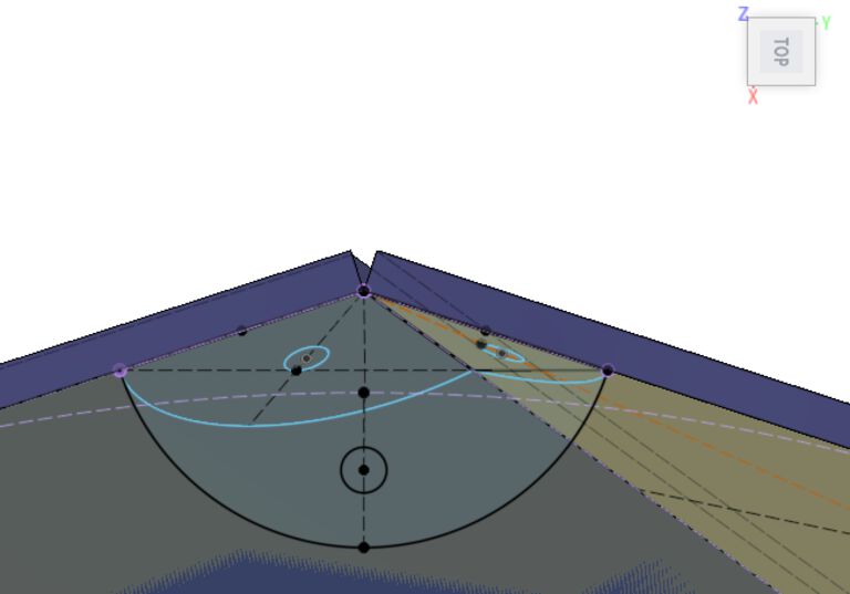
Write sketch to the body directly
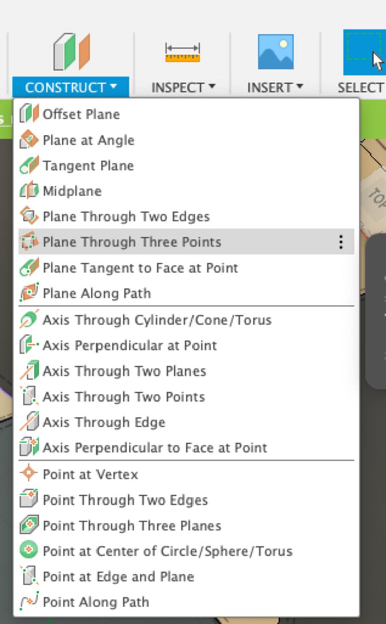
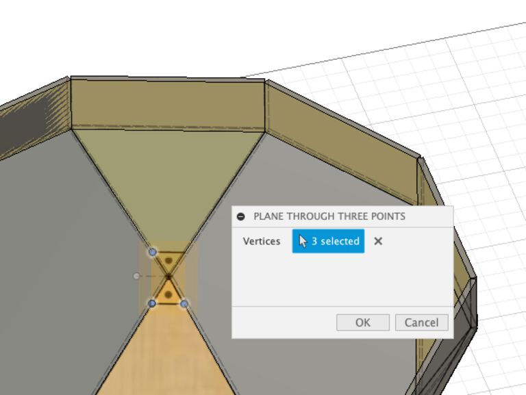
Construct > plane through three points
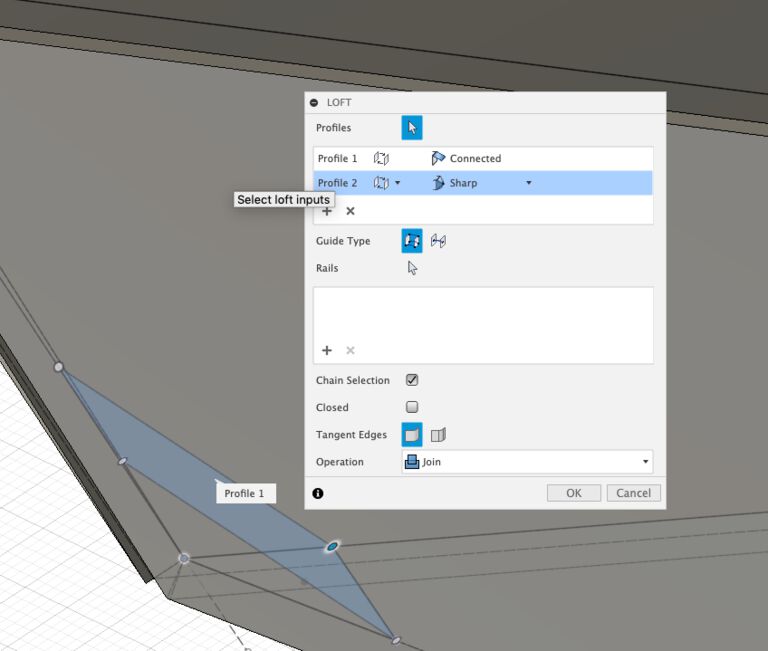
Loft - from constructed plane to the top edge.
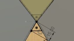
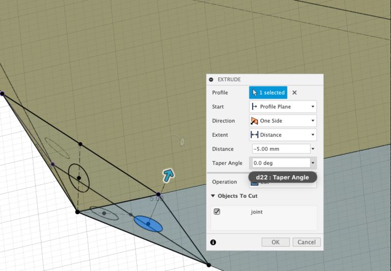
Create screw hole by vertical angle from the slant of each faces.
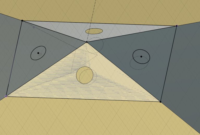
Then I moved the position of hole a little outer side for keep space to tighten screw.
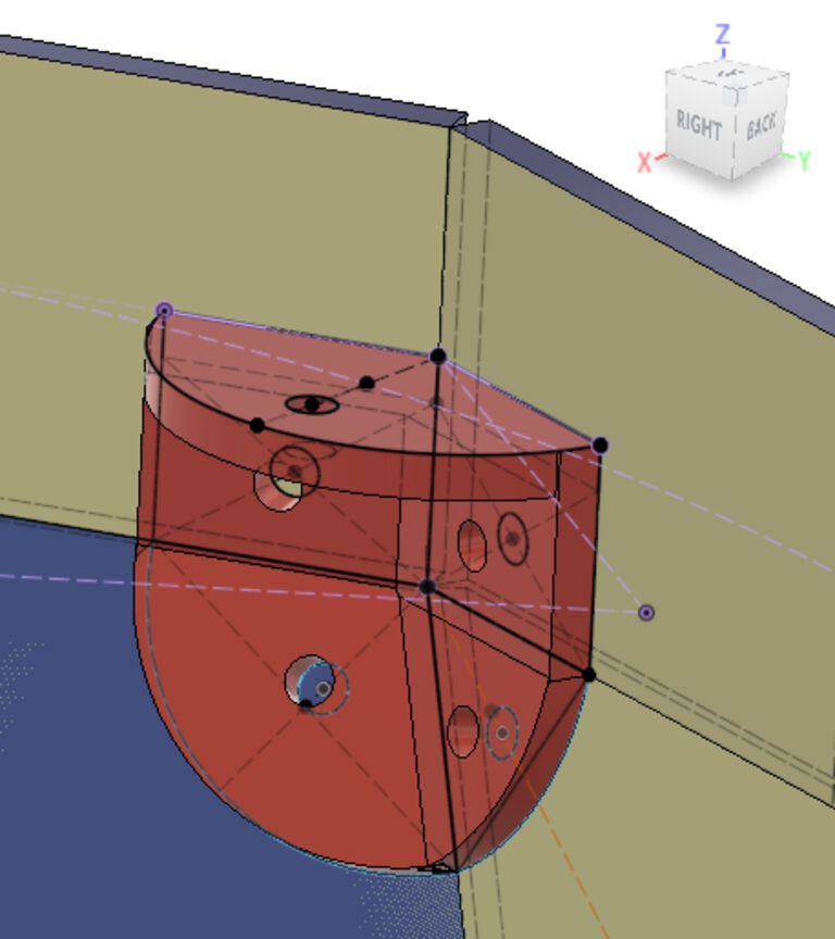
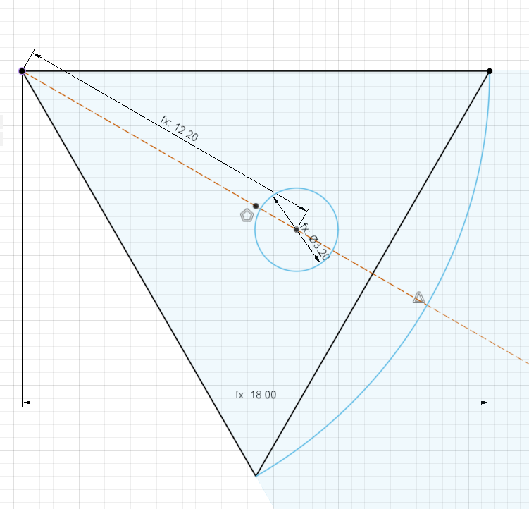
For joint to attache top decagon wall and acrylic table, I simply sketched to the bodies to be fixed and created screw hall.
Then extruded sketches for shape of joint.
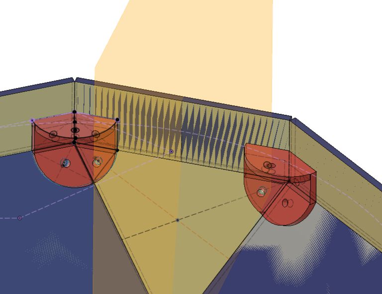
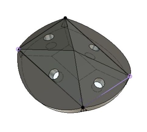
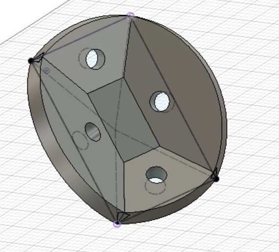
Once created one side of body, I mirrored to the other side of top rectangle by making center plane.
Then copied both by circular pattern of 5 for copying object and check the position of the screw halls of top decagon acrylic table.
The way to attache input devices
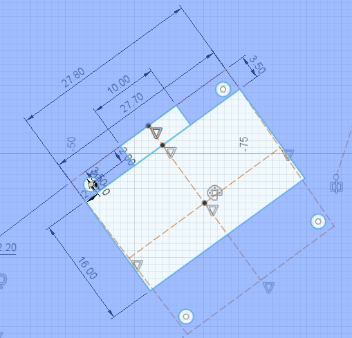
Potentiometers
I measured the diameter of knob of potentiometer(under 7mm) and a stopper(under 3mm) at the left.
Then distributes holes that align with pararel line of the edge of top decagon table.
OLED
For OLED, firstly I measured the screen size and the space for the pin head and made hole for the screen.
After experiment with real users(kids), they tend to push the OLED screen directly by their fingers and it looks to be fragile as an instrument.
That's why, I changed the design and just made a 2mm(+0.1 margin) hole of vertex of the device.
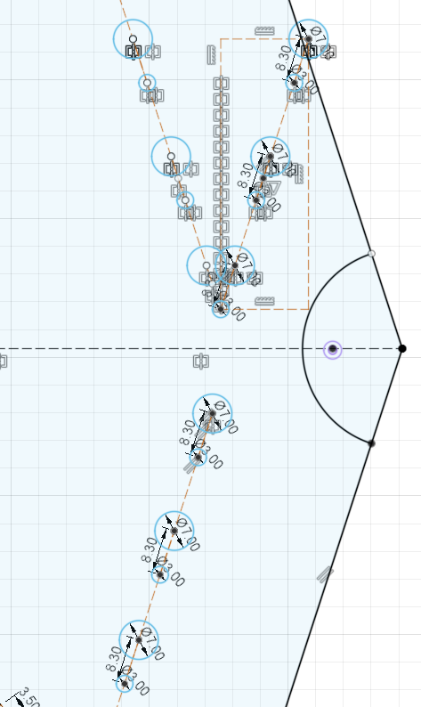
Tactile switches
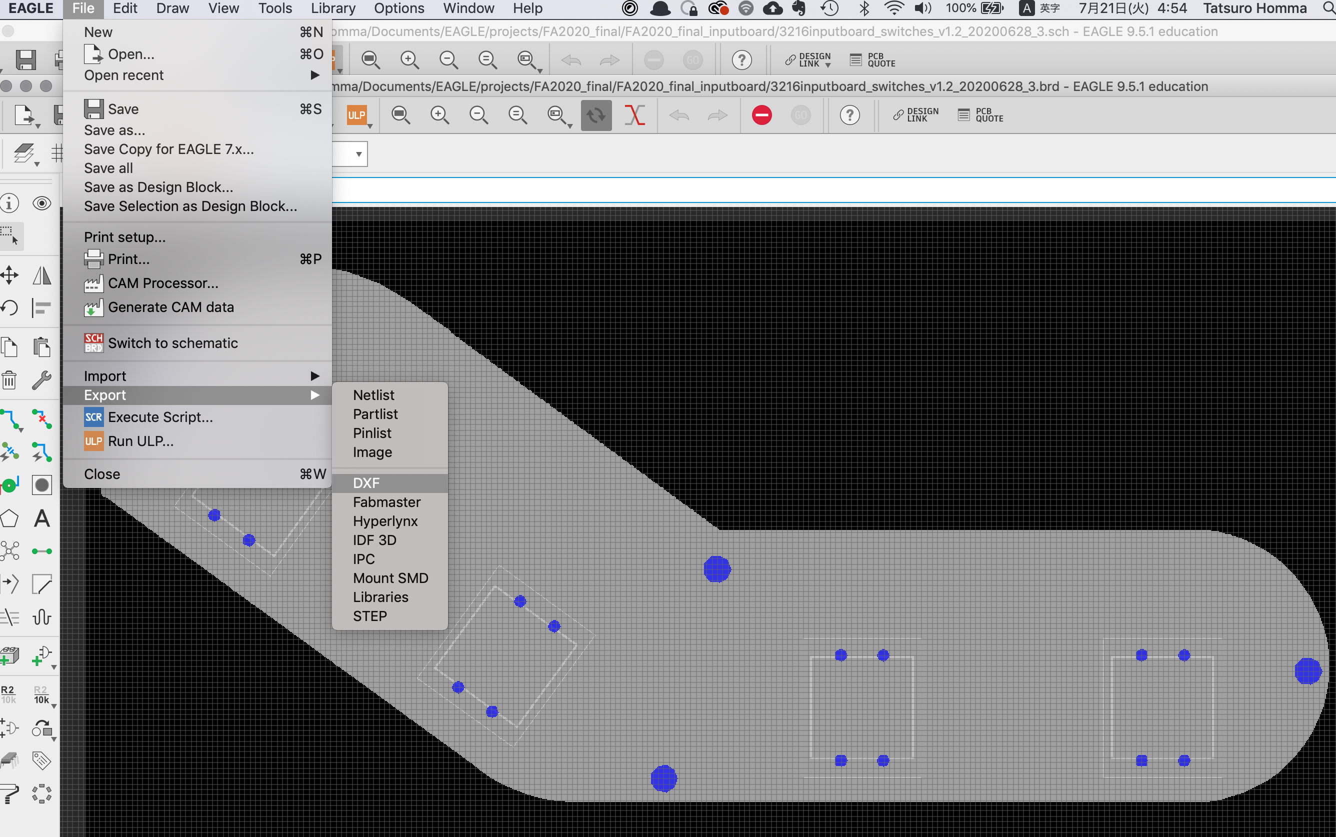
From EAGLE's board image (that activated limited layers of 48(document), 116(center drill) and 51(tDoc), I exported dxf file.
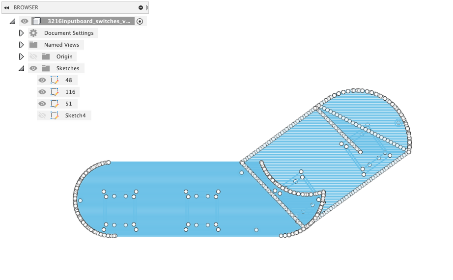
Importing dxf file into Fusion360 design, the image is quite heavy as it contains "48 document" filling the sketch by tons of edges.
It's good to use "51 tDocu" layer on Fusion360 sketch in this case.
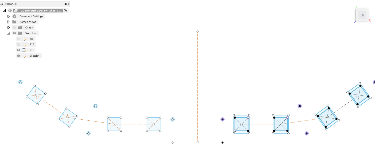
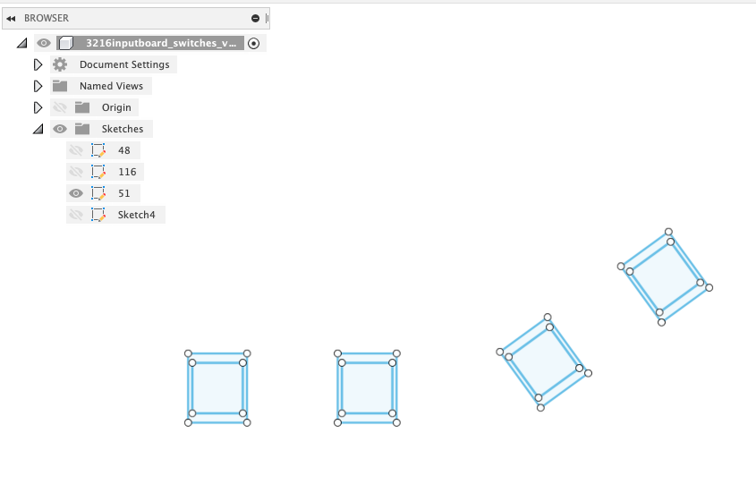
Then I mirrored the outline.
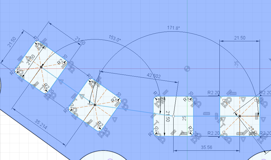
As I could not move the position of dxf file, I measurred the length, space between switches and angles, then redraw the sketch at the position where I want to create the hole on top.
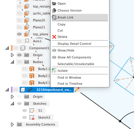
After making design, I found there is more efficient way to import EAGLE design to Fusion360.
- It's necessary to "Break link" to use the dxf design freely on Fusion360.
- Tamiya-san shared a procedure that "Convert To Wires" on 48 Document layer in EAGLE before exporting dxf.
Files
- PoTone Design
- 2D/3D design of PoTone : link to Autodesk A360, f3z
-
- Outline
- Joint
-
Fusion 360 models of joints are included in f3z file of 2D/3D design of PoTone
Reference
- Weekly Assignment