Project
Final Project
Week2-3 - Outline Design
Thorough week2 to week4, I picked some of my ideas about design in overall especially in outline of my Pot, then tried to use that in weekly assignment.
Outline Design (ver.1, week02)
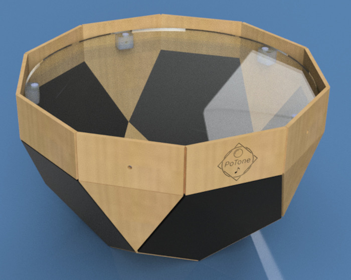
My final project needs a body in shape of "pot". For expanding user experience to take a photo, I want to make that body not only standing upright, but also standing diagonally. I came up with some ideas for holding the body in slanting degree (ex. fixing the body with screw that pinches the cover wrapping the base shaped in ball like right sketch). However, it adds complexity in design.
Instead, my idea is using "Johnson Solid", a set of shapes in convex polyhedron(凸多面体)each face of which is a regular polygon. My idea is using N25 Gyroelongated pentagonal rotunda that is likely to be a shape of pot (or cup?).
■Create 3D Model by Pentagonal RotundaInstead of folding, I make 3D design as follows. An instruction in this blog (in Japanese) helped me to make this.
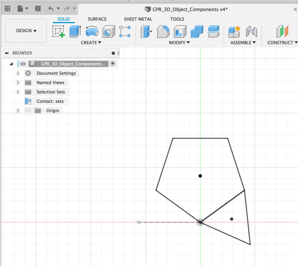
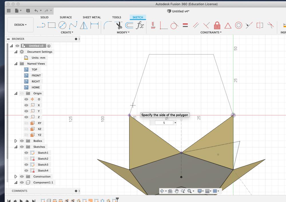
1. Sketch polygon(triangle and pentagon), add constraints of length as "dimension" and make construction line in horizontal position of opposite side, then end sketch.
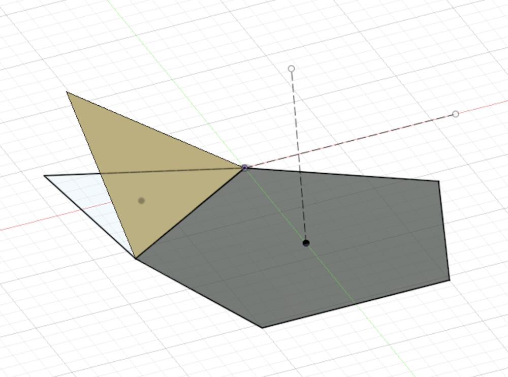
2. End sketch and check resolved line of revolve the side of triangle for finding intersect point of revolved vertex (pivoting bottom of triangle) and revolved side (pivoting the construction line at 1.).
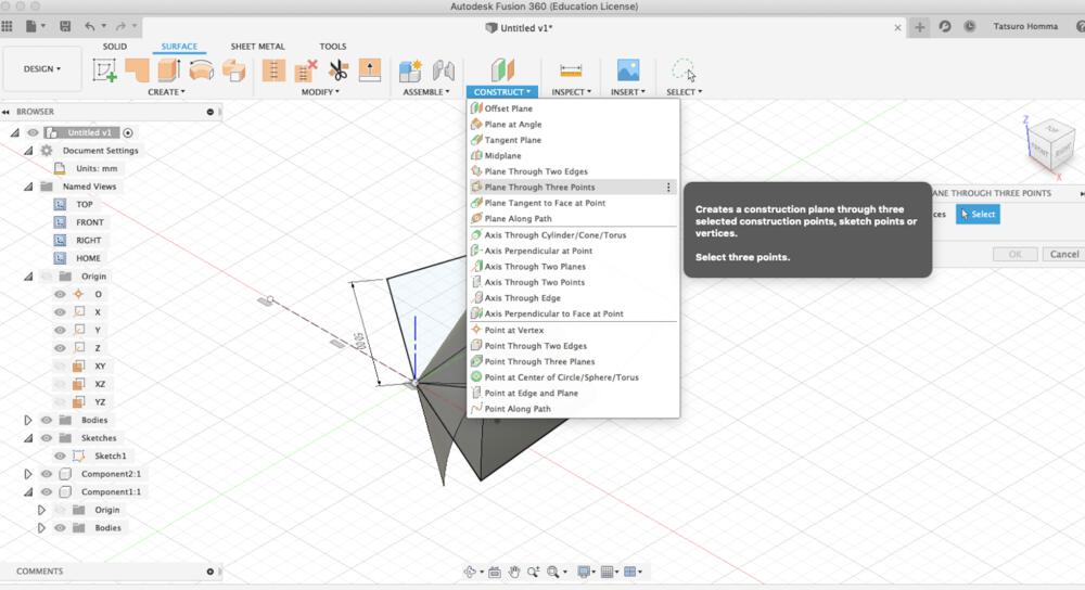
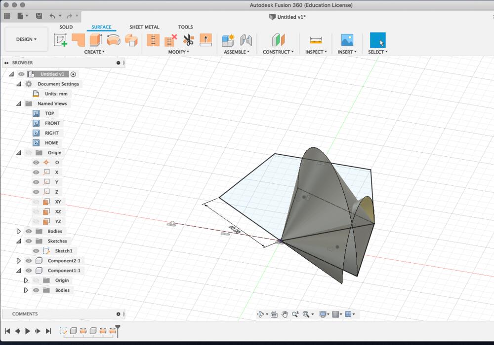
3. Construct > construction plane from three points
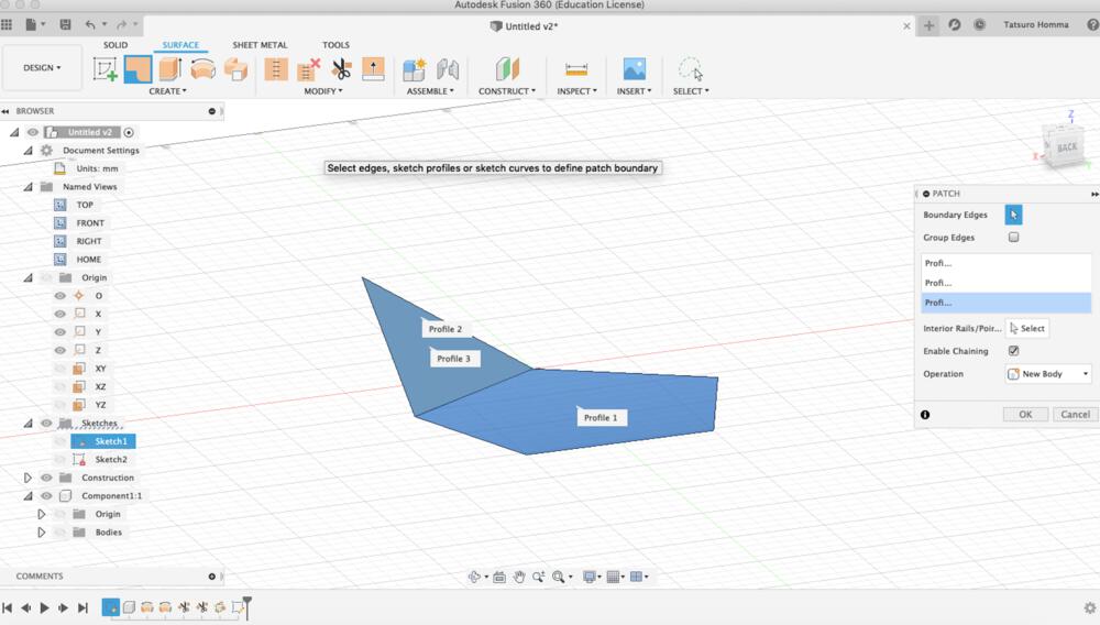
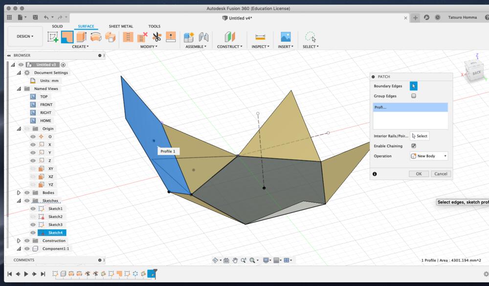
4. Sketch polygon(triangle) and create patch to surface of it and pentagon at the bottom.
5. Add a construction line as a central pivot of pentagon at the bottom.
_and_make_4_copies.png_1000x_q75.jpg)
6. Pattern > Circular pattern and make 4 copies of triangle by set a central contraction line(5.) as axis.
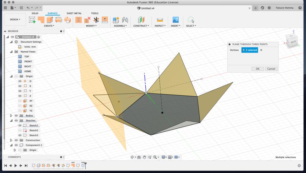
7. create a construction plane for side pentagon from three points of triangle.
8. sketch a edge polygon on construction plane of 7.
9. Add patch to added polygon.
_.png_1000x_q75.jpg)
10. Pattern > Circular pattern and make 4 copies of triangle by set a central contraction line(5.) as axis (same as 6.)
11. Repeat same process from 7. to 10. and make triangles to upper side.
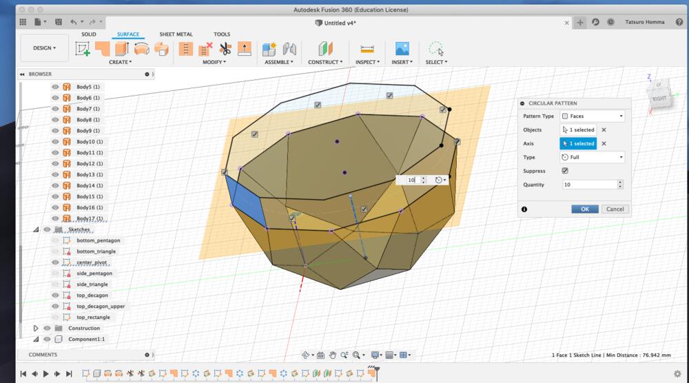
This image is making a circular pattern for side rectangle. I changed my mind to make rectangle instead of triangle for good usability to set or remove the front panel. For making the rectangle in the side, I constructed "offset plane" for upper side of decagon, create "project" line of the decagon and traced the line of it.
- "Thicken" the surface of patch. It's necessary to check the direction of the distance of thick. I set it into "from inside to outside"
- Sketch the "Center diameter circle" of top table at the "offset construction plane", then "extrude" it for giving thickness
- Sketch the "rectangle", "filet" and "extrude" of table stopper
- Make hole on the side rectangle using "extrude" the circle through table stopper ("to All")
- Make hole on the top table using "extrude" the circle through through the top table ("to All")
- Attach the tenon(ホゾ?) to the top of table stopper using "extrude" and "joint to obeject"
- "Make components from bodies"
- "Assemble > Joint" - attach table stopper to the inside of the side rectangle and top table to the table stopper
- "Design > Render" - set "appearance" and "scene"(background) of the object
- Put logo image to the surface using "Decal"
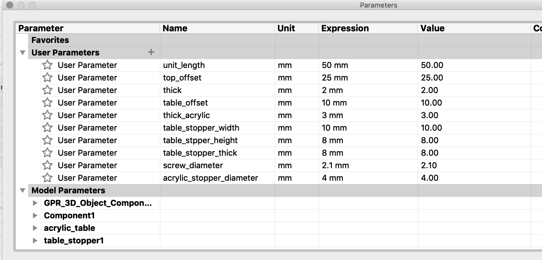
I tried to make every value of length, diameter and thickness as user parameter.
Some looks to be effective to reflect value to the model, but the others not because the way to make polyhedron(凸多面体) and constraint would have conflict..? This needs to be checked in next week activity of computer controlled cutting.
Paper Prototype (week03)
Concept of Construction Kit
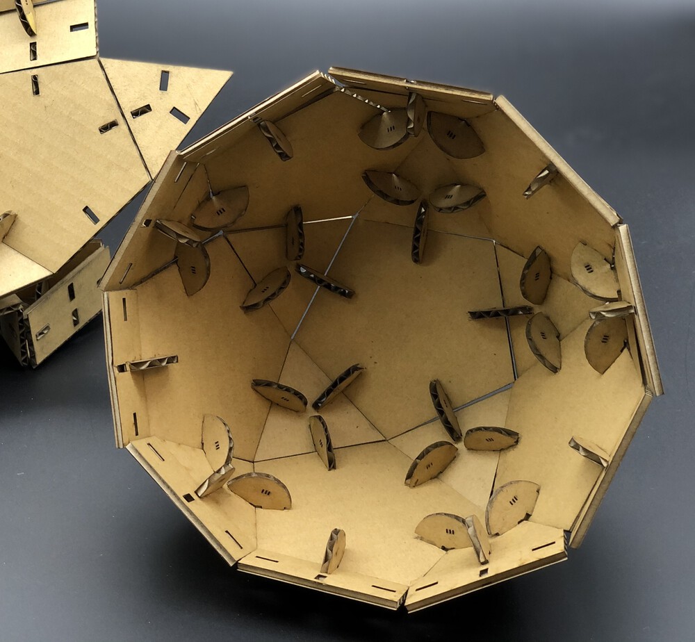
As the shape of my initial design of final project (a.k.a. "Pot") is polyhedron(凸多面体) - "Gyroelongated pentagonal rotunda" comprised by regular polygons, I came up with the idea of a constructional kit that can make polyhedron. The surface of shape would be polygons like regular triangle, pentagon and rectangle. Joint needs to have a function that can attache the surfaces in multiple angles.
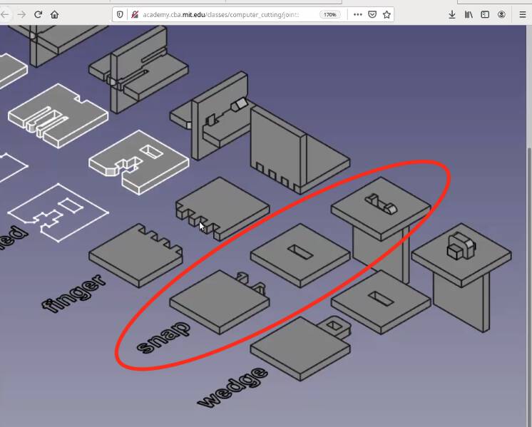
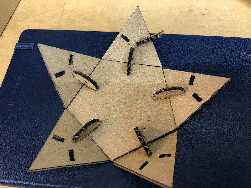
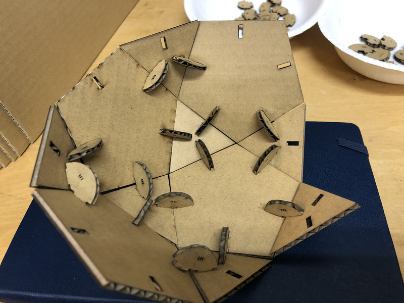
For attaching the surfaces, I decided to use the "snap" joint.
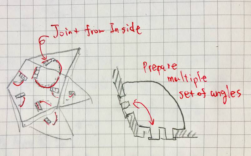
Joint from inside of polyhedron (not push out the edges as long as possible).
Multiple set of joint with different angles would allow players to make various constructional object!
Design of Construction Kit
Measure the angles in 3D Model
For attaching the surface of polyhedron, I measured the model that I made in week02.
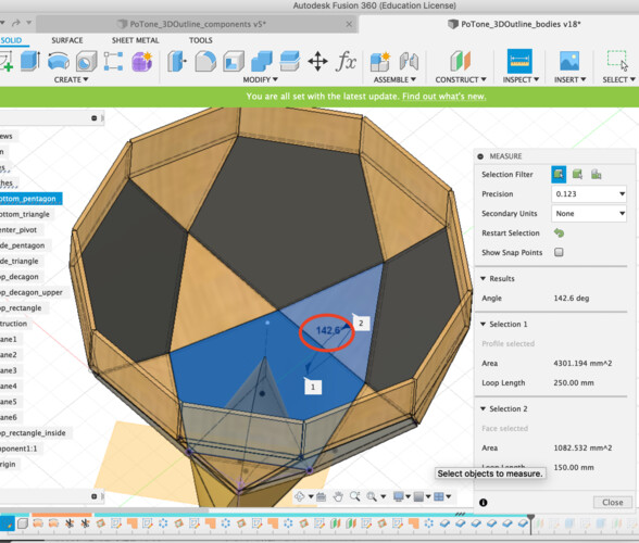
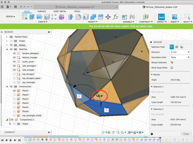
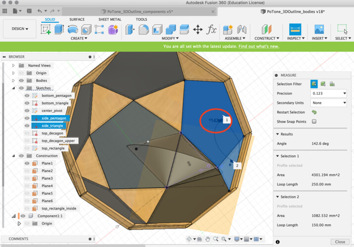
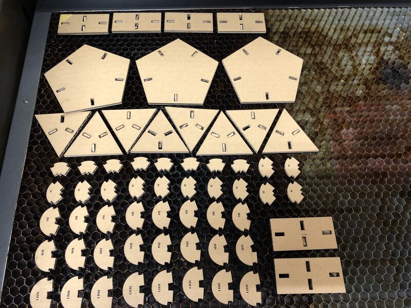
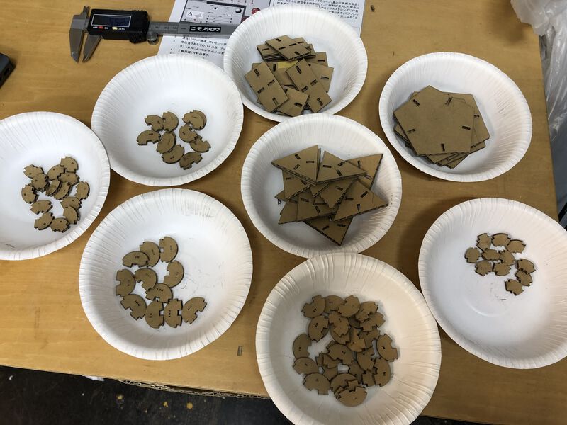
For making "Pot", I need at least following joint:
- 25 pieces of 142.6 deg. joint (pentagon and triangle)
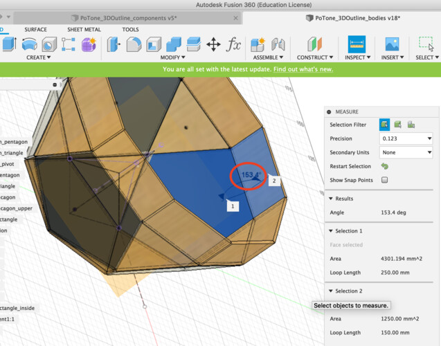
- 5 pieces of 153.4 deg. joint (pentagon and top rectangle)
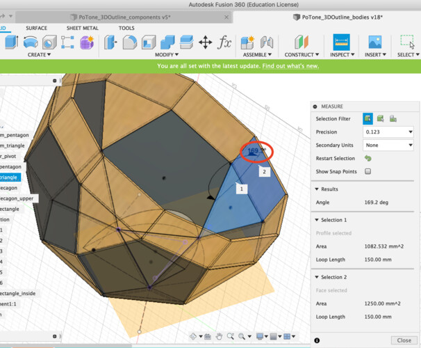
- 5 pieces of 169.2 deg. joint (pentagon and triangle)
And more for various constructions!
You can add the kerf as a parameter to every dimension of the shape for cutting. However, designing complex shapes like joint as above in that way is too difficult and too much constraint conflicts in CAD tool.
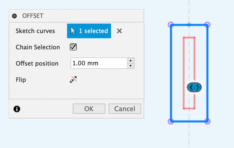
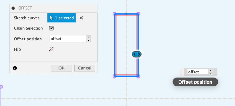
Instead, I used "Offset" function in the sketch of Fusion360 for spacint the line as the offset to desirable cutting edge.
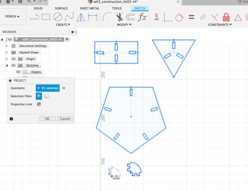
1. At the new sketch, create the projection line from original sketch (that is not reflected the kerf calculation).
2. In "offset" dialog, check the direction. If you want to cut outside of the shape, offset is external line. If inside, offset is internal line.
3. Reflect the offset line to the sketch.
Offset value is "a half of kerf". As I determined that the kerf for cutting cardboard in 3 mm thick is 0.35mm, the offset is set into 0.175mm
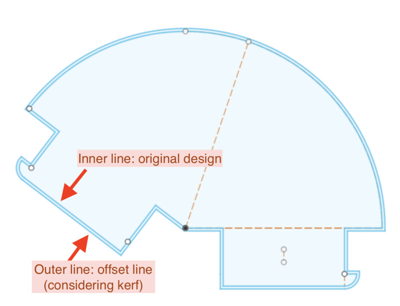
It's helpful to use offset function especially in considering kerf in complex design.
Generate the SVG file from Fusion360
There are several way to store the svg file to be accepted by cnc machines. For example, exporting dxf from Fusion360 and change it into svg from tools like Inkscape.
This time, I tried to use "Shaper Utility", a plugin of Fusion360. It's very straight forward to export svg file directly from 3D model using shaper utility.
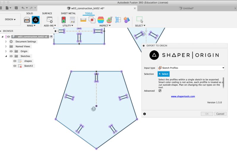
1. Tool > Shaper Utility and select "sketch profiles"
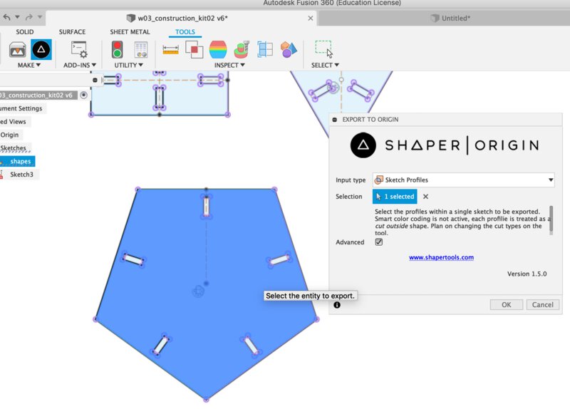
2. select the sketch profiles that you want to convert to SVG.
Occasionally, you cannot select the sketch profile especially in case of offset line. In that case, you can make body by extruding the offset sketch, check "single solid body" in 1., then you can get offset line of sketch.
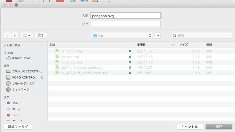
3. save the SVG file directly to local storage.
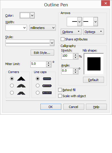
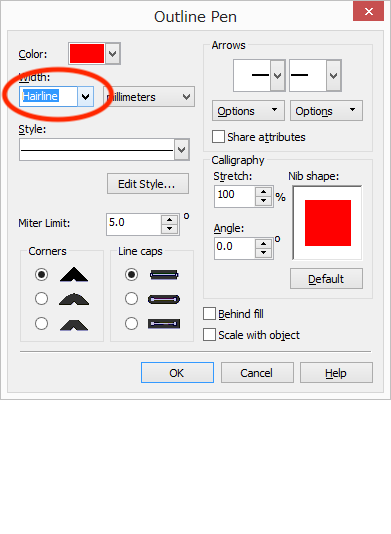
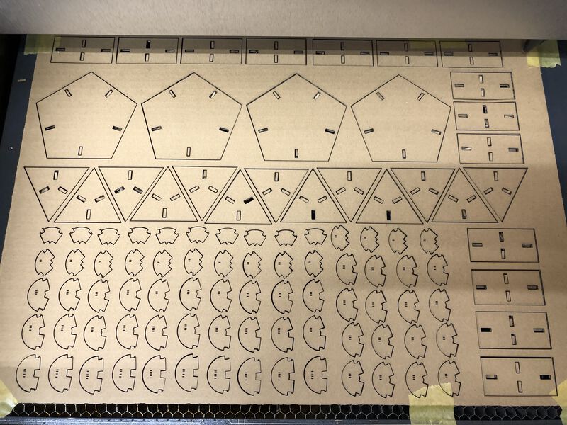
make the line for cut to ”hairline” and clear the color filled inside of the shape.
Following what I found on characterizing the laser cutter of Universal VLS Desktop VLS2.30 (especially in cutting a cardboard in 3mm thick), I set the parameter of Universal VLS Desktop VLS2.30 as follows.
| Color | Mode | Output | Speed | DPI |
| Black | Raster | 80% | 100% | 500 |
| Red | Vector | 50% | 4% | 250 |