Project
Final Project
The other board production for switches
I have created a schematic for connecting tactile switches. As I prefer the distribution fitting to the top decagon edges, I re-created a board design and assembled.
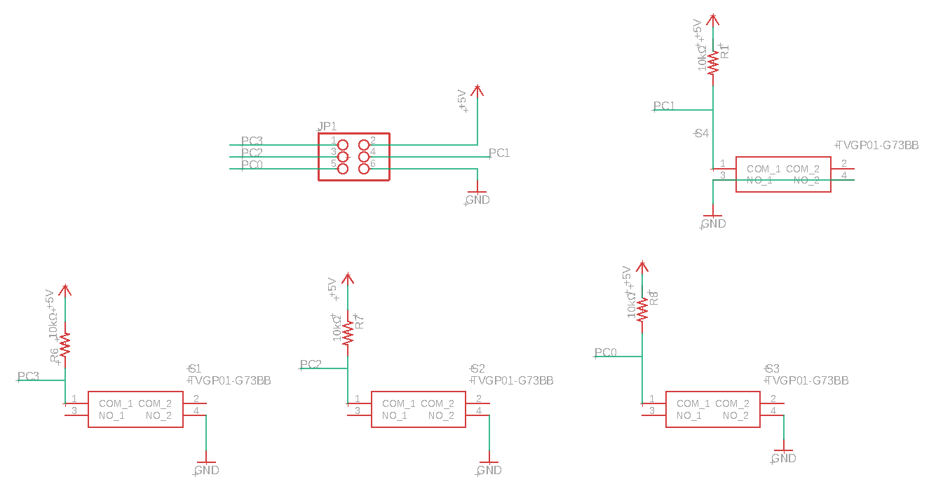
I used the same schematic connection. I copied it and made the new board pattern.
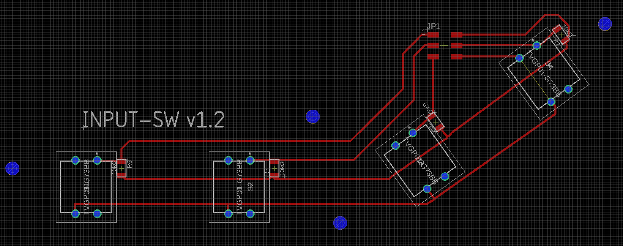
Made slant for 144 angle between 2 switches and 2 switches (that line gets along with edges of pentagon). The other circuit is the same as the former version.
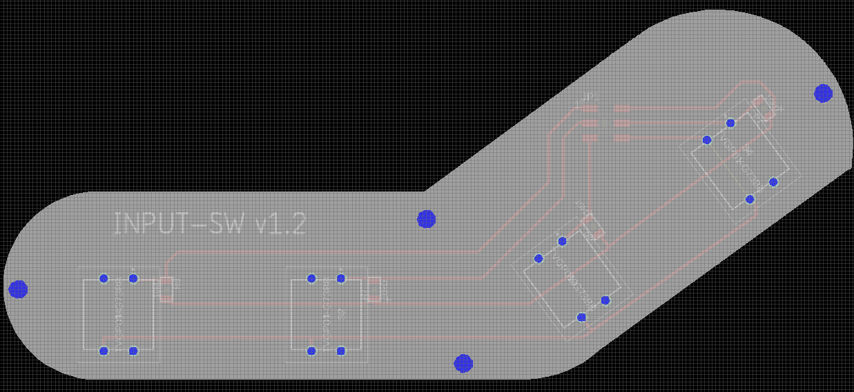
I added outline using polygon on EAGLE editor.
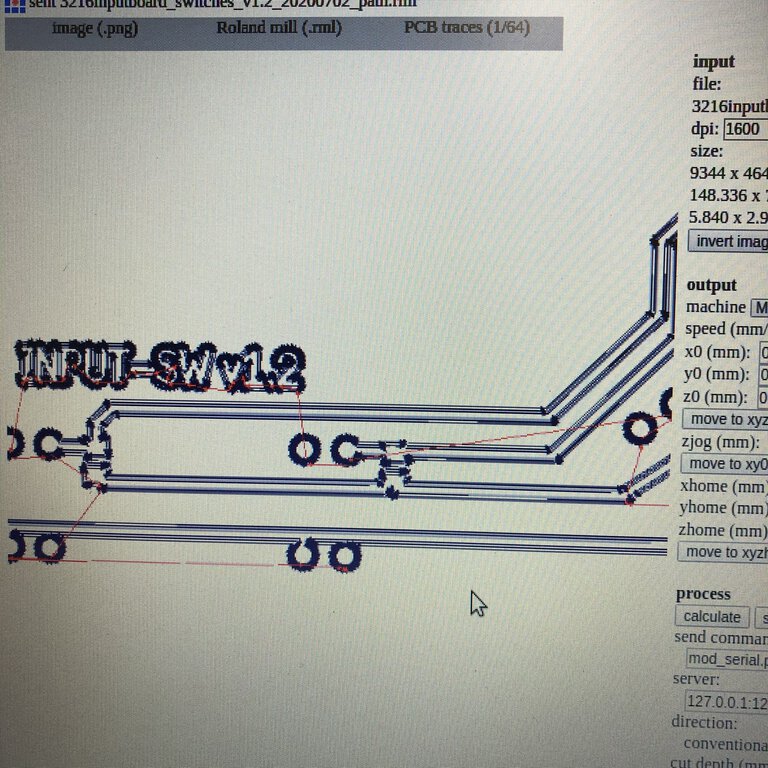
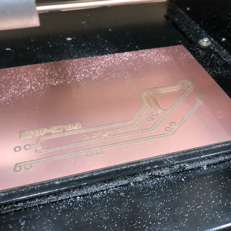
At this point, MODs did not work by unknown reason on the Xbuntu laptop PC at Fablab Kannai. So I crated cut path and mill it using Fab Module on the other laptop PC.
I used Roland MDX-15 for cutting INPUT-SW ver1.2 board using Roland MDX-15 as usual
Milling INPUT-SW ver1.2 board using Roland MDX-15
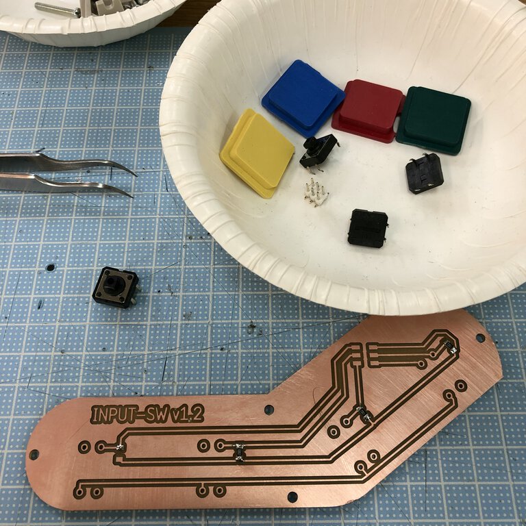
Soldered parts on INPUT-SW board. The parts are:
- 10kΩ (for pull up) resister x 4
- Tactile switches x 4
- 6(3x2) male vertical pin header x 1
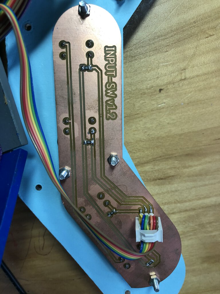
I solderred switches flipped side of the board, then kept a space between the board and top acrylic table by nut.
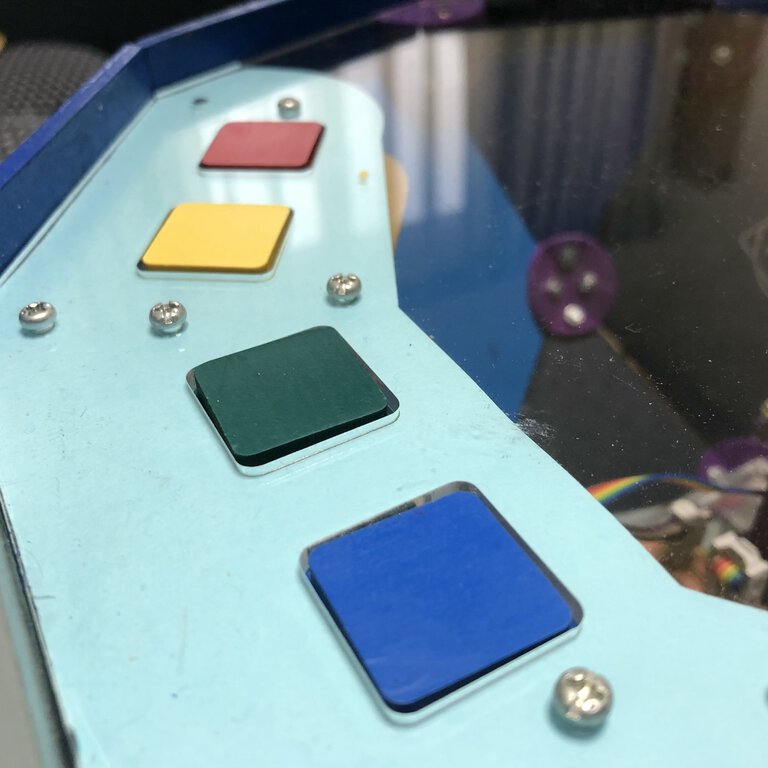
Finally, I put a cover item (that I made by casting) on top of tactile switch and fix it by acrylic table.