Project
Final Project
Output interface (Output devices(week 11) + α)
Requirement
For visualizing musical tempo, I add NeoPixel(WS2812B) as an output device.
Regarding NeoPixel(WS2812B), I added device information in weekly assignment page of output device.
Output Board
After I come back to lab from 2 months staying away days under COVID-19 situation, I created my original output board.
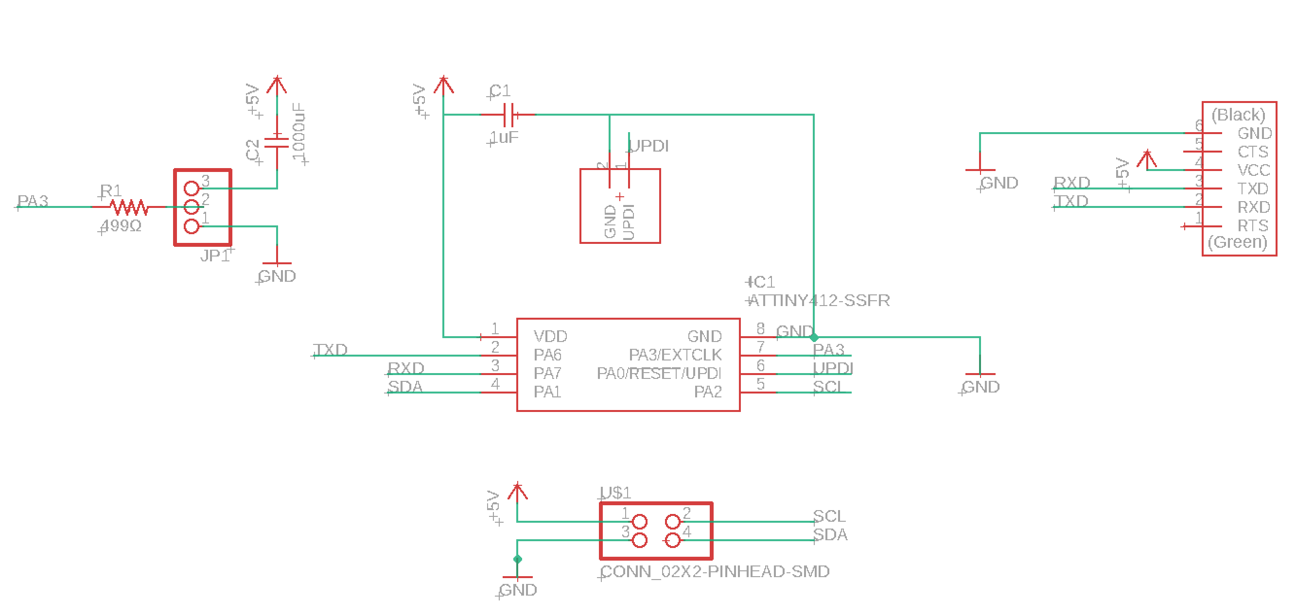
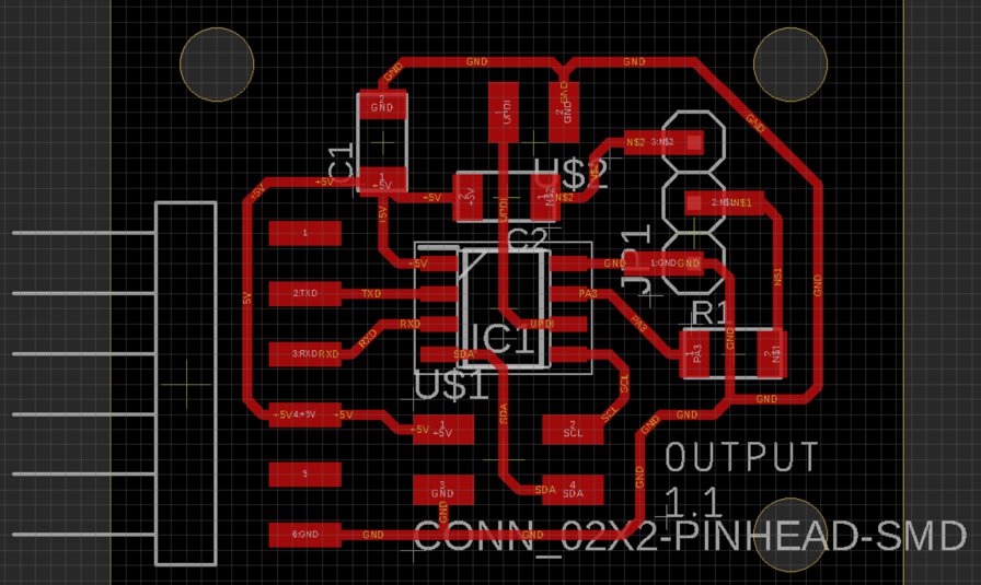
I use all the pins of ATtiny412:
- Control NeoPixel LEDs (PA3)
- Serial communication by FTDI-USB converter (PA6: TXD, PA7: RXD)
- I2C communication (PA1: SDA, PA2: SCL)
- Writing program by UPDI (PA0: UPDI)
- VDD, GND
Make Output Board
Firstly, I tried mods for milling output board. However, it did not work by some unsolved issue on the xbuntu machine in Fablab Kannai after coming back from staying away days under COVID-19 situation.
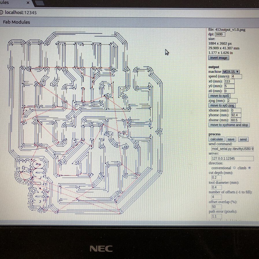
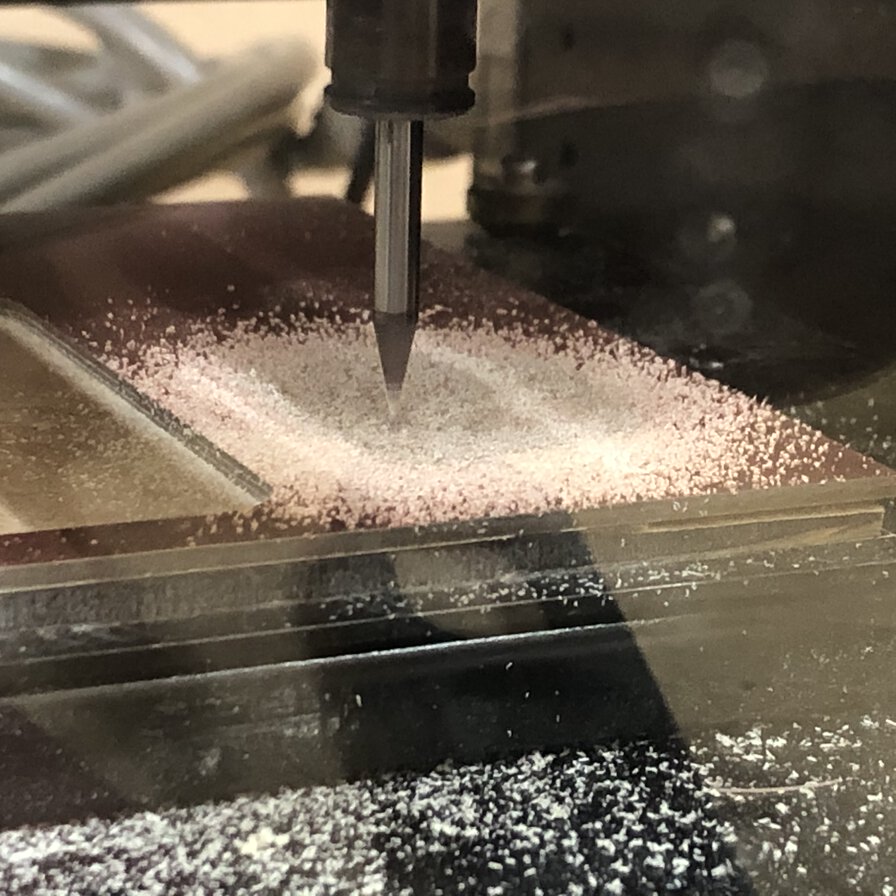
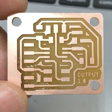
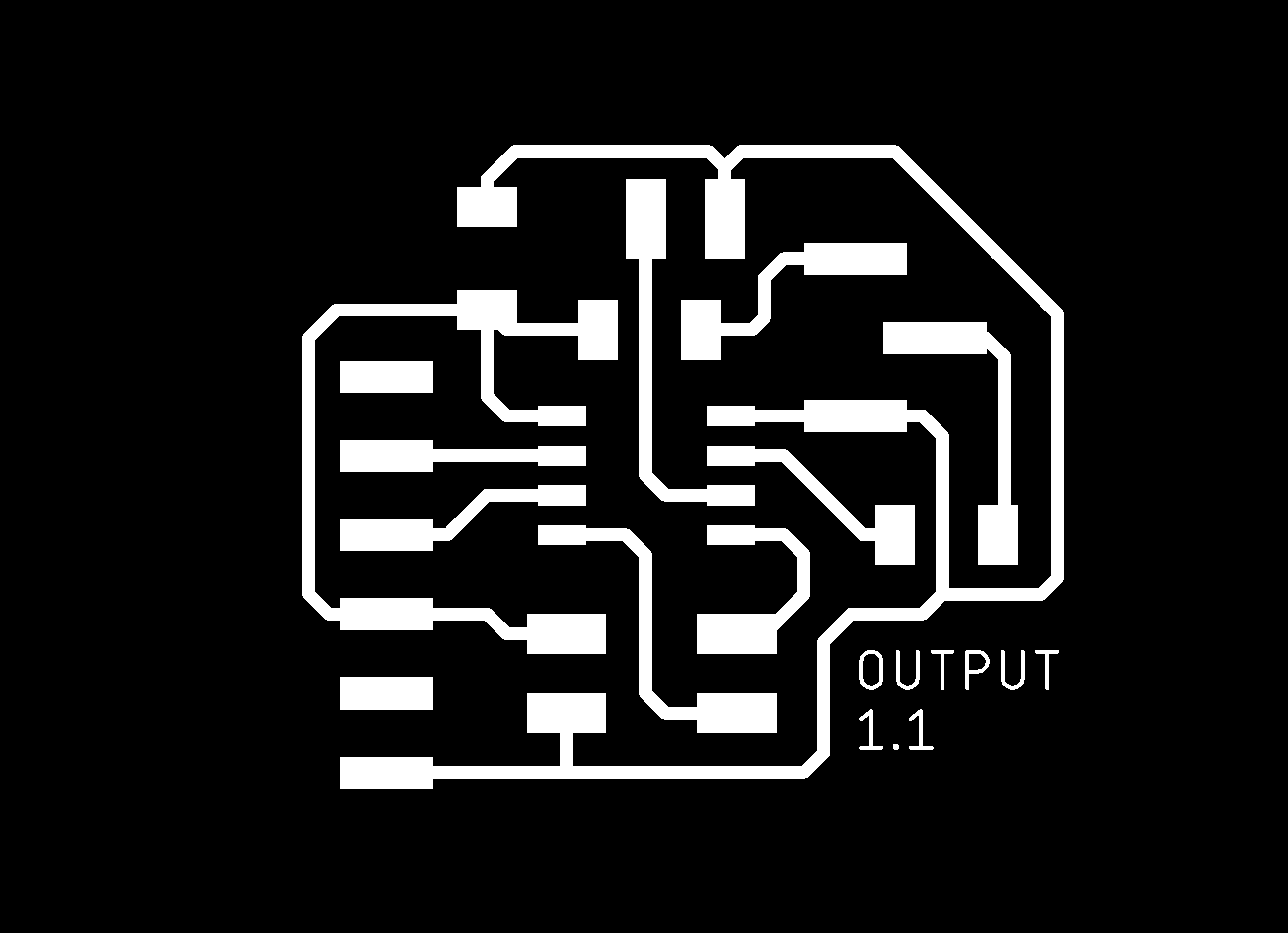
Alternatively, I used the other machine that installs Fab Module. It went well to make path, mill the trace by 1/64 inches endmill and the outline of board by 1/32 inches endmill.
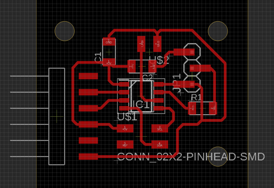
From lessons learned by making input boards in prior time, I tried to make it small as possible as I can. It would benefit me about low noise circuit and small milling time.
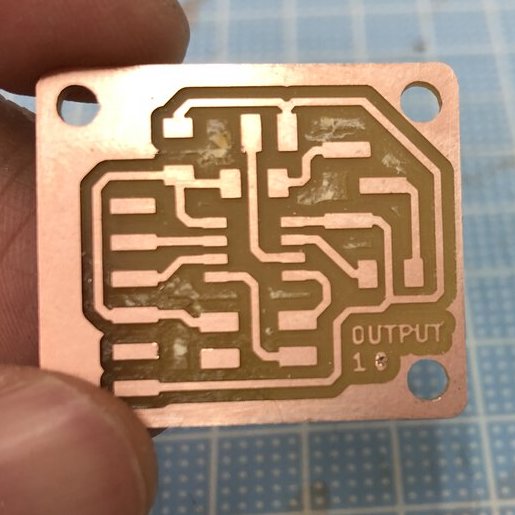
For avoiding noise or unintentional short in board, I debburred the board by steel wool(left). Then pealed off unnecessary parts by ultrasonic cutter.
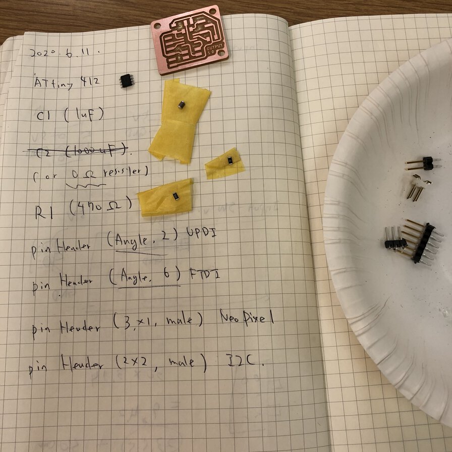
Soldered the parts.
- ATtiny412 micro controller
- Capacitor 1uF (C1)
- 0Ω resister (for bridging over a path line)
- 499Ω resister (prior to NeoPixel control pin (ref.)
- 2x2 pin header (I2C VCC and GND)
- 2 angle pin header (UPDI)
- 6 angle pin header (Serial communication over FTDI interface)
- 3 pin header for NeoPixel
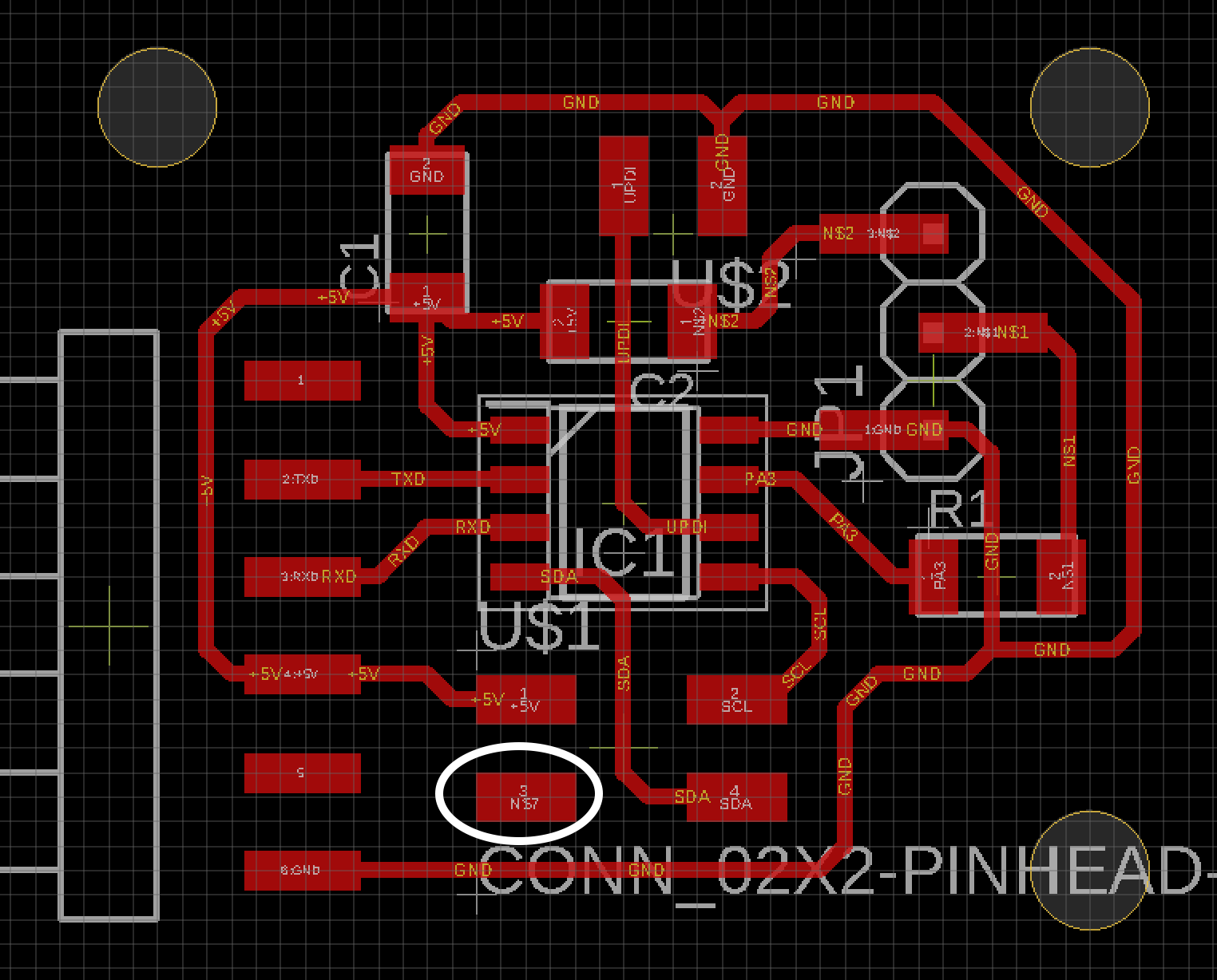
Then I found that a foot print of GND pin at 2x2 pin header is NOT connected to ground circuit on the board.
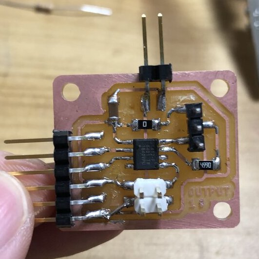
So, I patched to the above issue connecting the foot print of GND pin at 2x2 pin header to Ground circuit by foot line of resister and solder it.

Connection and test
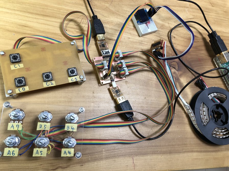
Then I connected the device and checked whether this board can controls LEDs on NeoPixel
I could check the interfaces (UPDI programming, serial communication and blinking NeoPixel) while I have an issue about blinking NeoPixel by ATtiny412.
Sample code that I embedded to test input board is tinyNeoPixel_sample_412_0613_2.ino. Above connection is a little bit complicated, but I tested output device only using 3 pins of Vcc, data(PA3) and GND for testing the board.
Experiment result (and related issue) was written in group assignment page of Fablab Kannnai in week of output device.