Assignment
Week11: Output Devices
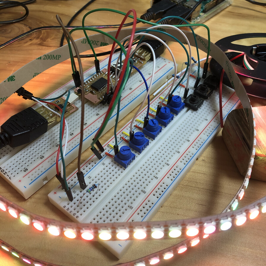
Table of content
- Assignment
- My Work
- Group Assignment
- NeoPixel
- NeoPixel with Arduino UNO
- Write NeoPixel program to AVR 1 series microcontroller
- NeoPixel on Attiny3216 controlled by potentiometer
- I/O Board Design and Test
- Refine I/O Board Design(version 2)
- Original board for output device
- Consideration about performance of I/O Board
- Files
- Lessons Learned
- References
Assignment
- individual assignment
- add an output device to a microcontroller board you've designed, and program it to do something
- group assignment
- measure the power consumption of an output device
My Work
Group Assignment
add an output device to a microcontroller board you've designed, and program it to do something(link )
NeoPixel
I got NeoPixel WS2812B Led Strip, array LED at Aliexpress.
NeoPixel is Adafruit's brand for individually-addressable RGB color pixels and strips based on the WS2812, WS2811 and SK6812 LED/drivers, using a single-wire control protocol
It was very straight forward to do an experiment using Arduino library for that device. However, using it in AVR1 Series controller requires some cosideration(TBD).
NeoPixel with Arduino UNO
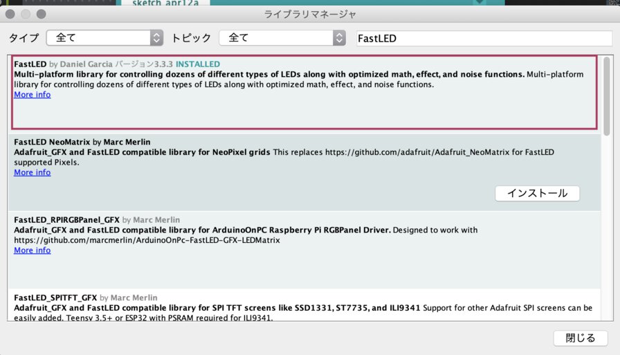
I referred information in WS2812B datasheet and a blog(in Japanese) and tried to experiment using "FastLED" library.
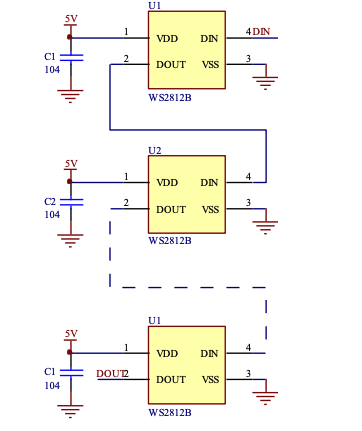
Because the circuits of voltage, ground are linked and the data transffer circuits are cascaded over multiple LED, we only needs one pin(PIN3 in this example) for controlling the device.
Library1: FastLED_arraytest.ino
Using FastLED, Arduino code can assign set of LEDs to the elements of array in Arduino language.
Library 2: NeoPixel_arraytest.ino
Using NeoPixel library by Adafruit, I could get the same outcome with FastLED.
Experiment
Libraries of FastLED and NeoPixel support to control LED arrays.
Write NeoPixel program to AVR 1 series microcontroller
I tried to write above programs to my ATtiny3216 breakout board. I could compile a program using library 2: NeoPixel by Adafruit while a program using library 1: FastLED cannot be complied
Compile program using "FastLED" library for Attiny3216 (Failed)
Compiling with the board setting of ATtiny3216 was failed with messages that some of register value in FastLED library are not supported in ATtiny3216.
Compile program using "NeoPixel" library for Attiny3216(Worked, but does not support 20MHz clock speed)
At first, compiling a program using "NeoPixel" library for ATtiny3216 was failed with the message of "CPU SPEED NOT SUPPORTED".
  /Users/tatsuro.homma/Documents/Arduino/libraries/Adafruit_NeoPixel/Adafruit_NeoPixel.cpp:1124:3: error: #error "CPU SPEED NOT SUPPORTED"
  #error "CPU SPEED NOT SUPPORTED"

           ^~~~~
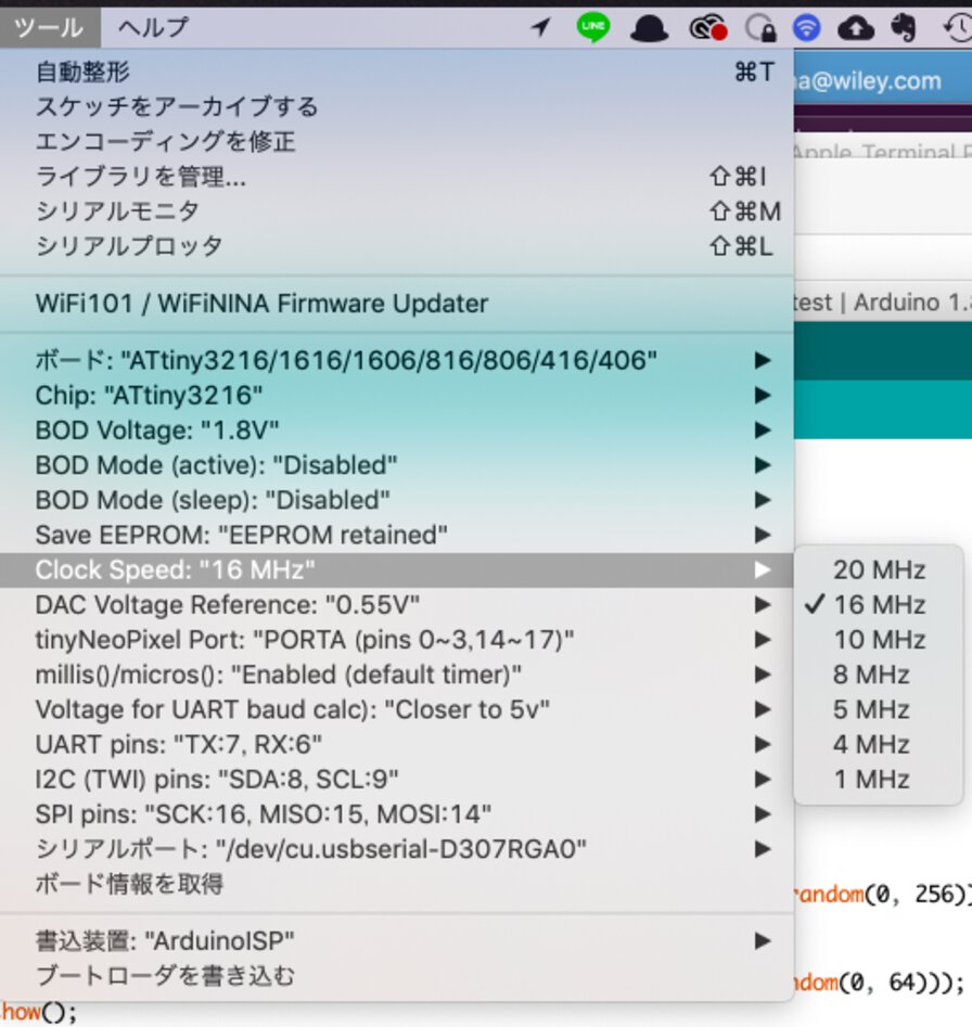
I changed the "Clock Speed" from "20 MHz" to "16 MHz". Then I could compile the program successfully.
Write "NeoPixel" program to Attiny3216 (Macbook Pro)
pin PA7 of ATtiny3216 is assigned to Pin 3 of Arduino.
// switch to build path on terminal
$ cd ~/Arduino/build
// set local into virtual environment
$ pyenv local 3.7.0
// check the python version of virtual environment
$ pyenv versions
system
* 3.7.0 (set by /Users/tatsuro.homma/Arduino/build/.python-version)
3.7.0/envs/scraping
scraping
$ pyupdi.py -d tiny3216 -c /dev/tty.usbserial-D307RGA0 -b 57600 -f NeoPixel_arraytest.ino.hex
Programming successful
It's the same way to write program in week of electronics design(week6), embedded programming(week8) or input devices(week9).
The behavior of the program on Attiny3216 is the same as the one on Arduino Uno.
NeoPixel on Attiny3216 controlled by potentiometer
NeoPixel_arraytest_potentiometer.ino
pin PA7 of ATtiny3216 is assigned to Pin 3 of Arduino.
pin PB4 of ATtiny3216 is assigned to Pin 5 of Arduino.
Experiment
A Library of NeoPixel support potenteiometer to control LED arrays.
While above component worked in terms of coordination between input and output devices, I found that serial monitor values did not show in correct format when I lowered the clock speed: 16MHz"
I added following code to above code of "NeoPixel_arraytest_potentiometer.ino"
  void setup() {
    /* other code */
    Serial.begin(115200);
  }

  void loop() {
    /* other code */
    Serial.print("sensor value: ");
    Serial.println(sensorValue);
  }
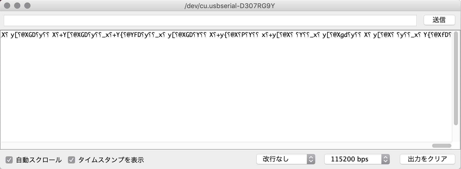
However, charactors in serial monitor of Arduino IDE is garbled and there is no line feed.
Though I tried to change the baud rate of Serial.begin() and serial monitor interface like 74880, 57600, ... 9600, 4800,.. it cannot be resolved.
Library3: FastLED_arraytest.ino
Compile program using "tinyNeoPixel" library for Attiny3216 - Worked!
After I took time to investigate this, I found a git hub page of "tinyNeoPixel - a megaAVR compatible library for WS2812 "NeoPixel" and similar". It says "This library adapts the Adafruit_NeoPixel library to work with the megaAVR architecture, and adds support for 10MHz and 20MHz clock speeds"
Viewing code base at Github, it seems to have already been unified to "Adafruit NeoPixel Library".
Then I changed the code as follows.
tinyNeoPixelTest.ino
And I could compiled the program with the "Clock Speed" setting to 20MHz successfully. Finally, I could get see correct value on monitor over serial interface.
I/O Board Design and Test
At this point(as of 21 April), my idea for final project is using the same microcontroller of ATtiny3216 to input (multiple potentiometers and switches for controlling MIDI parameters) and output device(NeoPixel displaying tempo).
To avoid making too large system, I prefer to make one board for input and output devices altogether using ATtiny3216 microcontroller.
I want to check program library dependencies, functional behavior and performance of input/output board.
As I do not have access to lab due to shutdown by COVID-19, I proceed by designing the I/O board.
In week of "Input device", I designed my original input board that can be utilized in my final project. For connecting NeoPixel(WS2812B) to my input-output board, I added 1x3 pin header library (from Libraries > Managed Libraries > Eagle Pcb > pinhead.lbr) to the input board schematic.
[ Input Output board v1 Schematics ]
Before designing board pattern, I experimented by original input/output board using original Attiny3216 breakout board.
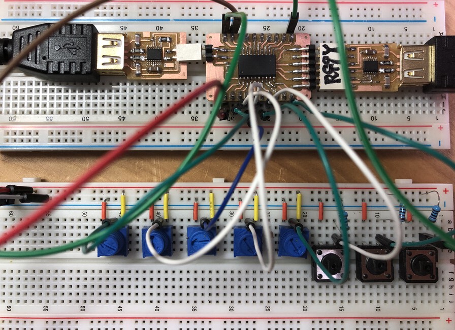
Then I wrote test code that controls NeoPixel behavior by 5 potentiometers and 3 switches.
testInOutBoard.ino
Overview of testIOnOutBoard program
- PA3: NeoPixel - output
NeoPixel is controlled by:
- PA4: potentiometer 1 - Color(Red)
- PA5: potentiometer 2 - Color(Green)
- PA6: potentiometer 3 - Color(Blue)
- PA7: potentiometer 4 - length of LEDs
- PB5: potentiometer 5 - blink interval
- PB4: switch 1 - delay of loop()(+250 msec)
- PB1: switch 2 - delay of loop()(-250 msec)
- PB0: switch 3 - mode(single:0, rondom:1)
Experiment of testInOutBoard.ino
Refine I/O Board Design (Input Output Board version 2)
When I experimented above using tinyNeoPixel library, I found that it worked but a connector of jumper pin on breadboard linked to NoePixel data pin got hot several minutes after switched on.
Also, I found some cases (an example) that uses resister for data pin and capacitor for VCC pin for NeoPixel(WS2812B).
My instructor, Tamiya-san, checked an sketch example of tinyNeoPixel library and found an important alert in comment of source code of "Sketch Example > tinyNeoPixel > strandtest" saying:
// IMPORTANT: To reduce NeoPixel burnout risk, add 1000 uF capacitor across
// pixel power leads, add 300 - 500 Ohm resistor on first pixel's data input
// and minimize distance between Arduino and first pixel.  Avoid connecting
// on a live circuit...if you must, connect GND first.
Then, I changed the schematics of I/O board pattern
[ Input Output board v2 Schematics ]In my home, I have 470Ω resister but I do not have any capacitor. So that, I added only 470Ω resister and experiment how it works.
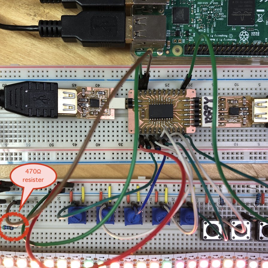
This is the compostion of experiment at this time. I added a 470Ω resister between data pin of NeoPixel(WS2812B) and microcontroller on breadboard.
After I added resister, the issue of heating pin of NeoPixel seems to be resolved.
Also, for writing program to ATtiny3216 breakout board and serial communication monitoring with it, I changed my host computer from macbook pro to Raspberry Pi. This is because it looks that the behavior of USB type C connector or the adapter of USB type C-A is not stable. After I changed to Raspberry Pi, failure of pyupdi works very fine :) About setup, see page of Raspberry Pi Tips - Setup pyupdi
I changed testInOutBoard.ino for easier experiment that can adjust the number of LEDs in 0, 18, 36, 72, 144(max number of my NeoPixel LED is 144) by pushing switch.
testInOutBoard_v2.ino
Hero shot of this week!
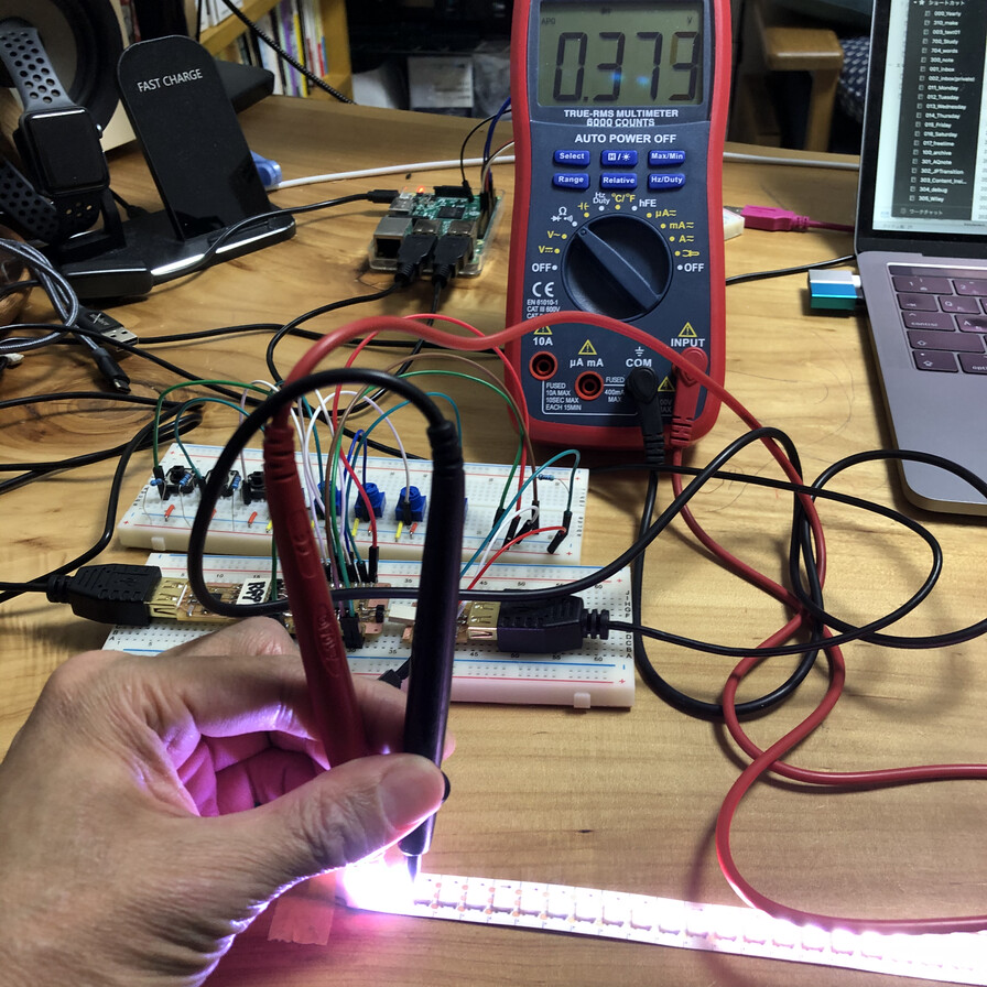
Then I checked voltage, current, resister, diode or frequency. I add the outcome to group assignment page
Timelapse - checking current value by number of LEDs in NeoPixel
Original board for output device
After I caught up with the access to lab (it's caused by government restriction under COVID-19), I made my original board for output devices for my final project. I documented about it in my output device page in my final project.
Consideration about performance of output device
My I/O board program(testInOutBoard_v2.ino) waits until NeoPixel finishing the blink of sequence of LED in loop() of Arduino code. As I want to blink light in interval of music tempo, It might be better to have separate microcontrollers for input and output device.
I checked "protothread" (Original C library by Adam Dunkels and Arduino library provided by Robotics Back-end) that makes progarm behave "like" worker thread. Basically, AVR serires does not support multi thread programming, but protothread and similar libraries provide infinite timer value for separate blocks of program function. Using that timer, we can provide program work like worker thread on Arduino.
Reading through Arduino Protothread tutorial by the Robotics Back-End website, and experimented simple example, I could compile a program including "pt.h" library for Arduino Uno board or ATtiny3216. However, when I call "Serial.write("message") inside of protothread, another protothread is blocked.Seeing the tutorial, there is a description saying:
Important things to know about Portothreads
- The execution of your code inside a protothread must be fast (between two PT_WAIT_UNTIL), or else you will block the rest of the program. Remember: true multi-threading doesn’t exist on Arduino, only one line of code is executed at a time. So, don’t use delay() or any other blocking function, ever.
Files
Lessons Learned
- It's important to check library dependencies to the microcontroller feature. Even it is compiled safely, it's not possible to work expectedly (like Serial communication with tinyNeoPixel on 20MHz clock speed).
- There are many consideration points on designing electronics circuit - current, voltage, heat, capacitor etc.
- At this point, I did not experiment PWM setting as I will not use that in my final project so far. However, seeing the other Fab Academy students works, I want to check that if I have a chance (in week of mechanical design?)
References
- NeoPixel
- WS2812B (Ver.5) datasheet
- "tinyNeoPixel - a megaAVR compatible library for WS2812 "NeoPixel" and similar"
- Astroai-Digital-Multimeter,-Trms-6000-Counts-User-Manual-jp.pdf