Assignment
Week15: Molding and Casting
Assignment
- individual assignment
- design a mold around the stock and tooling that you'll be using, mill it (rough cut + (at least) three-axis finish cut), and use it to cast parts
- group assignment
- review the safety data sheets for each of your molding and casting materials, then make and compare test casts with each of them
My Work
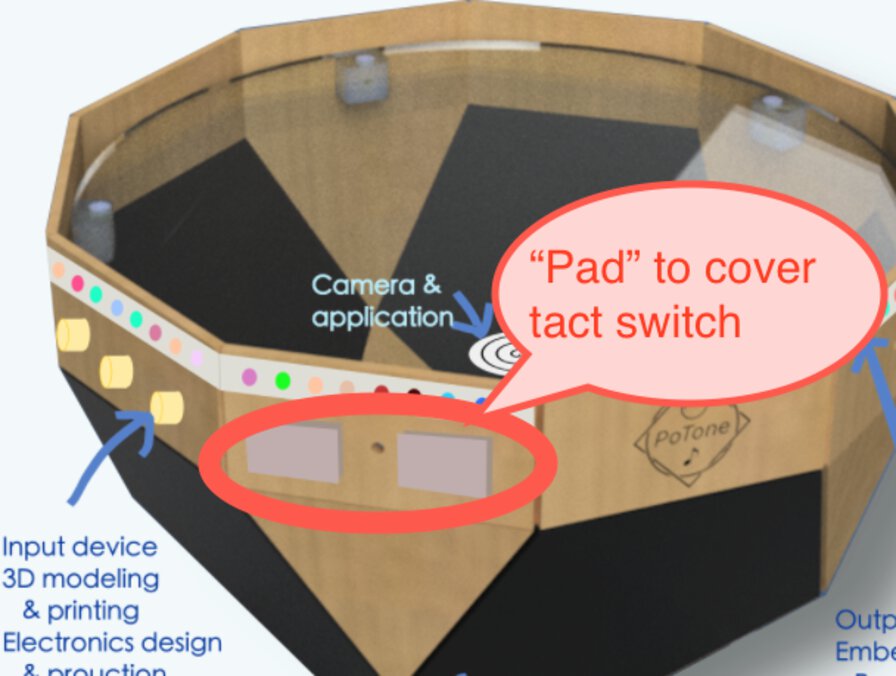
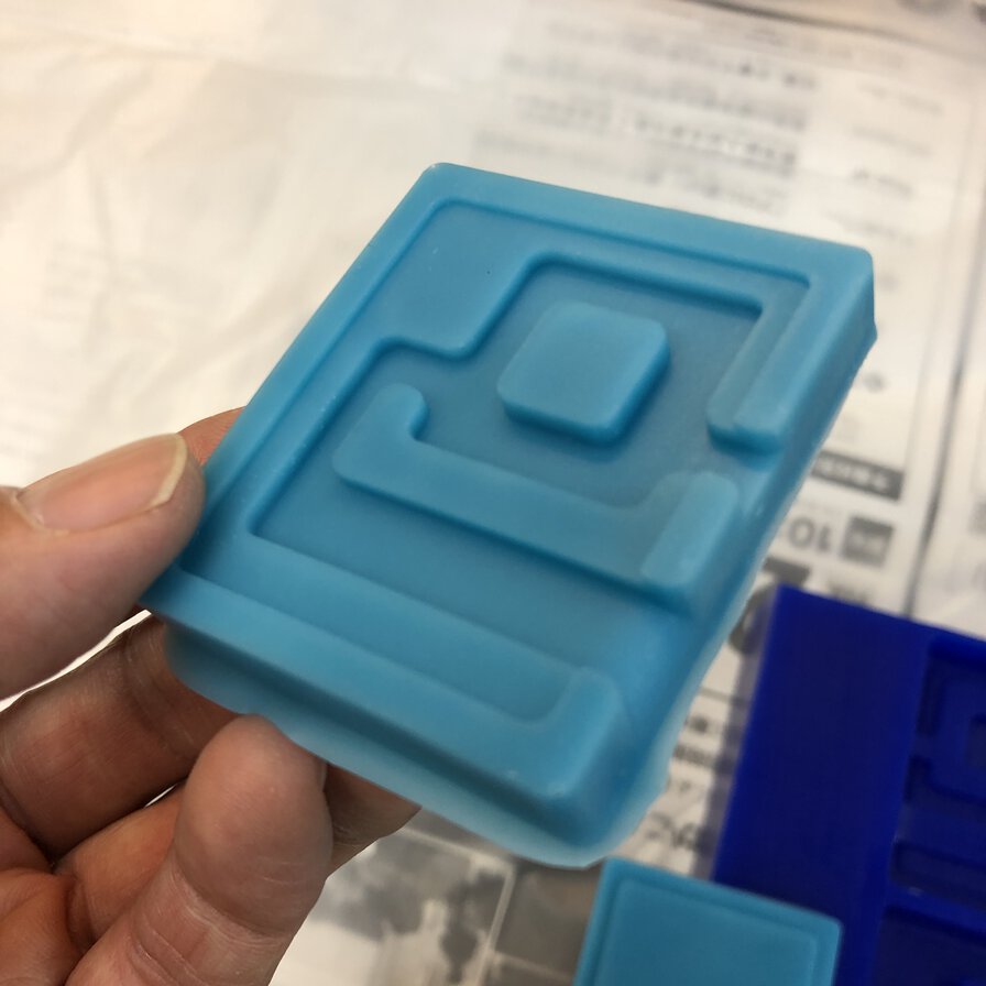
I want to make a cover top of tact switches by urethanes resin that I will use for my final project.
After input week(25 March), we've never had chance to access to lab at Kannai due to virus. Under that situation, what I did for this week are:
- Read through safety data sheet (as a group assignment)
- Checked tools and materials
- Make models for 1)"pad" (final material to be cast), 2) a mold of "pad" and 3) a cut wax to cast the mold.
- Make tool path to cut wax and simulate that
I will make mold and cast physically after I go back to lab.
Group Assignment
review the safety data sheets for each of your molding and casting materials, then make and compare test casts with each of them(link )
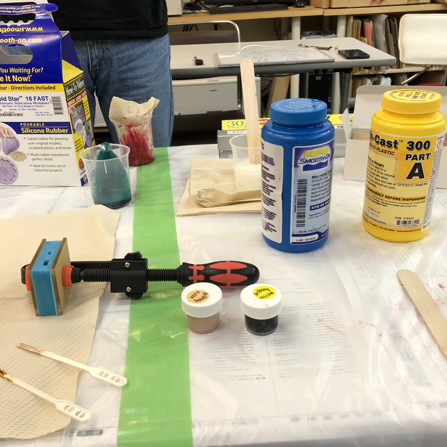
Tools and materials at Fablab Kannai
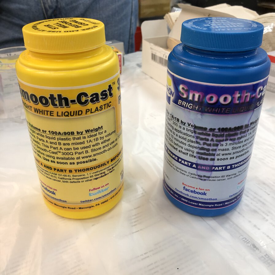
My instructor, Tamiya-san shared tools and materials that I can use for molding and casting. For this assignment, I will use modeling wax for milling the "mold" of "mold", use Smooth-on MOLD STAR 16 FAST for mold and use Smooth-on Smooth-Cast 300 to cast.
Tool
- Milling machine: Roland MDX-15
- Endmill (Ref: Carbide Depot
- CAM software: MODELA player 4
- Simulator: Virtual MODELA
| No. | Type (FL: number of flutes, SE: square end) |
|---|---|
| CU 130007 | 0.0625” DIA 2FL SE AlTiN 1/16 |
| CU 136596 | 0.1250” DIA 4FL SE LONG AlTiN 1/8 |
| CU 132075 | 0.0625” DIA 2FL BALLNOSE AlTiN 1/16 |
| CU 137212 | 0.1250” DIA 4FL BALLNOSE LONG AlTiN 1/8 |
Material
- Modeling wax (machinable wax)
- Ferris File-A-Wax, Blue
- 92 x 152 x 39 mm
- Safety Data Sheet & Technical Data Sheet
- Mold
- Smooth-on MOLD STAR 16 FAST
- Color: Blue-Green
- Mix Ratio: 1A:1B by volume / 1A:1B by Weight
- 0.9 kg x 2
- Pot Life: 6 min (Time to be dispented)
- Cure Time: 30 min (Time to fix)
- Temp: 450F 232C (dualable tempercher)
- Technical Bulletin
- Shore A Hardness: 16A
- Safety Data Sheet
- Cast
- Smooth-on Smooth-Cast 300
- Mix Ratio: 1A:1B by volume or 100A:90B by weight
- Mixing Tool: metal, glass or plastic
- 0.9 kg x 2
- Color: White
- Pot Life: 3 min
- Cure Time: 10 min
- Technical Bulletin
- Safety Data Sheet
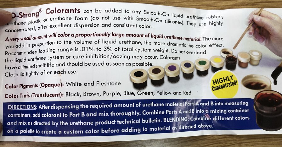
- Liquid urethane colorants
- Smooth-on SO-Strong
- 0.01% - 3% of the total weight (Parts A + B mixed) of the material being cast
- Technical Bulletin
- Safety Data Sheet
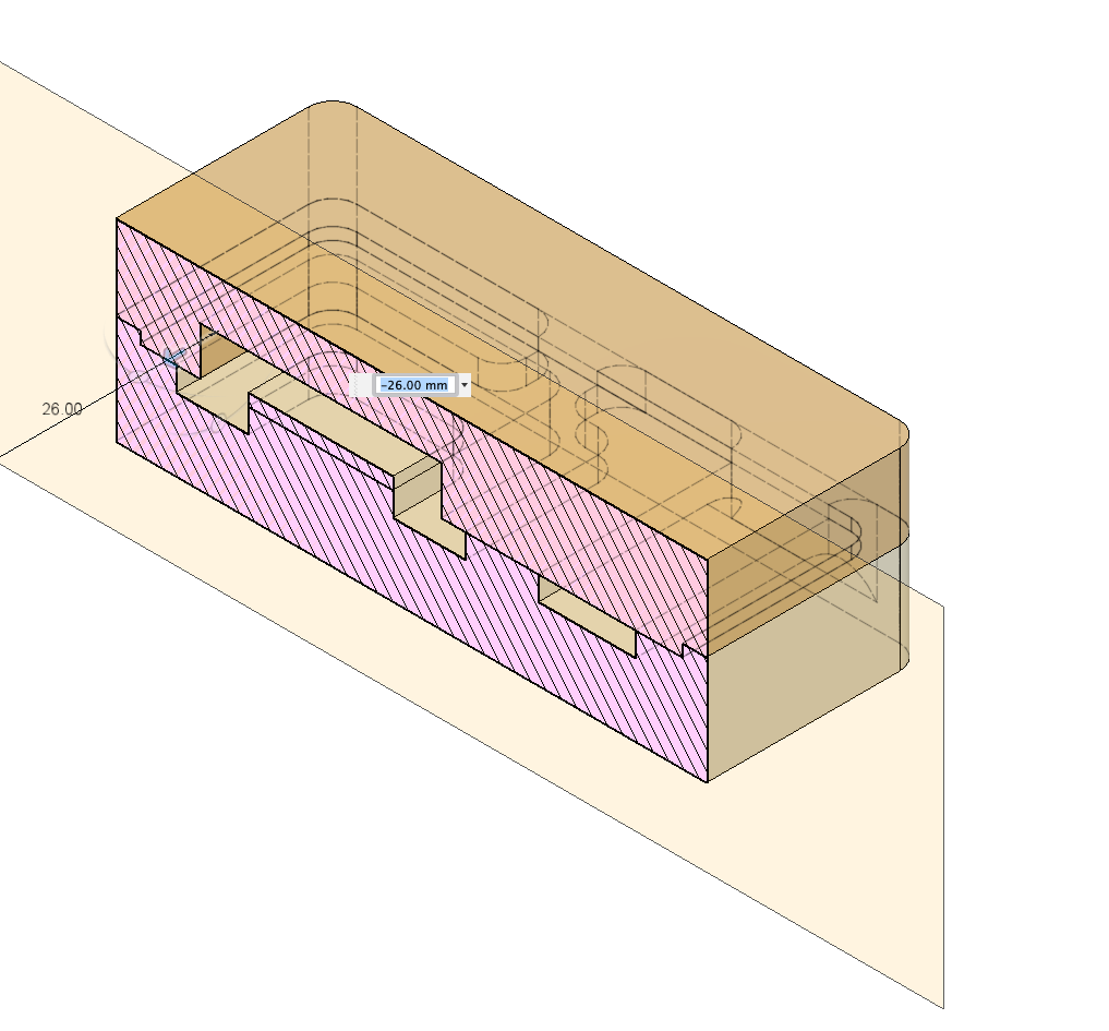
- divide the mold into two parts calculating height of the surfaces
- made the bulge and hollow surrounding the edge parts of pad for fixing the joint position of top and bottom parts (this works as registration key between two parts' mold).
Fablab Kannai has the other materials like low melting-point metal and plaster.
Model
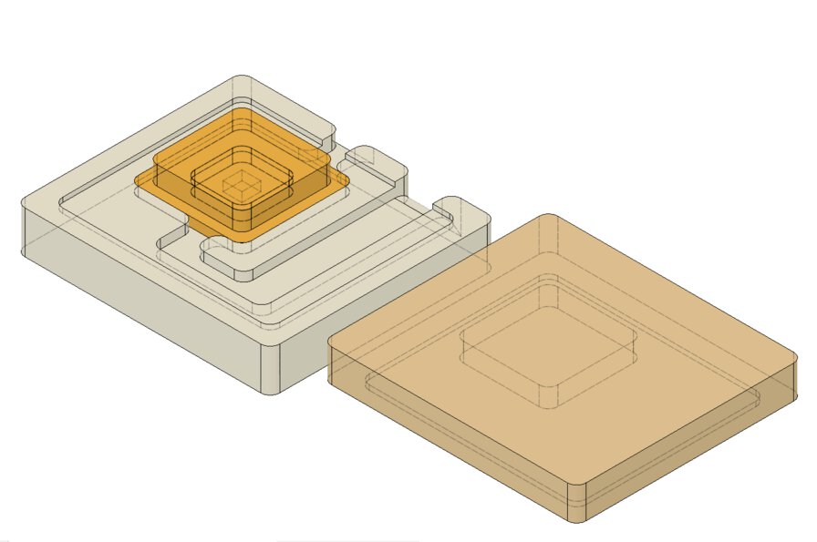
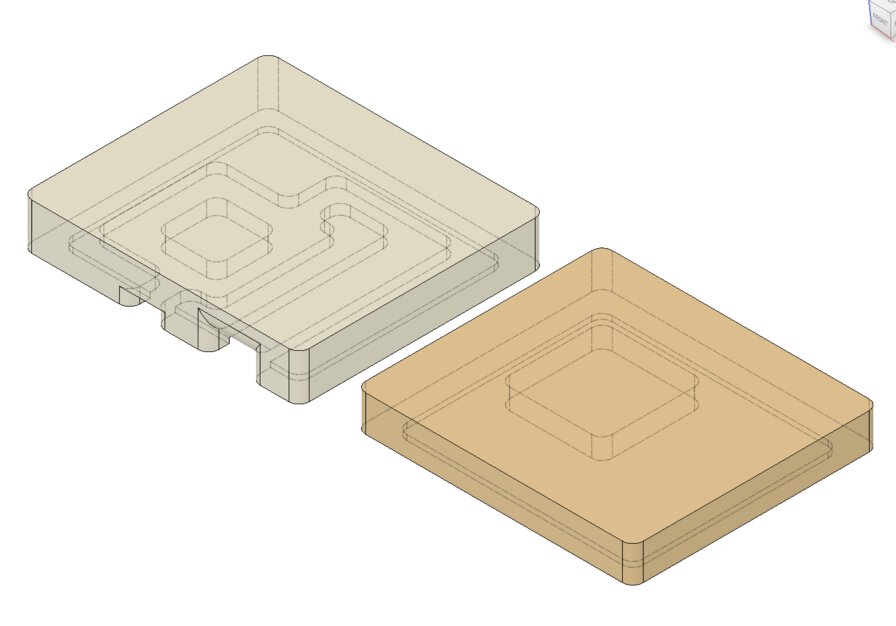
For making the mold, I made a 3D model of 1)"pad" (final material to be cast), 2) a mold of "pad" and 3) a mill wax to cast the mold by Fusion360.
1) Model: Pad - final artifact to be cast
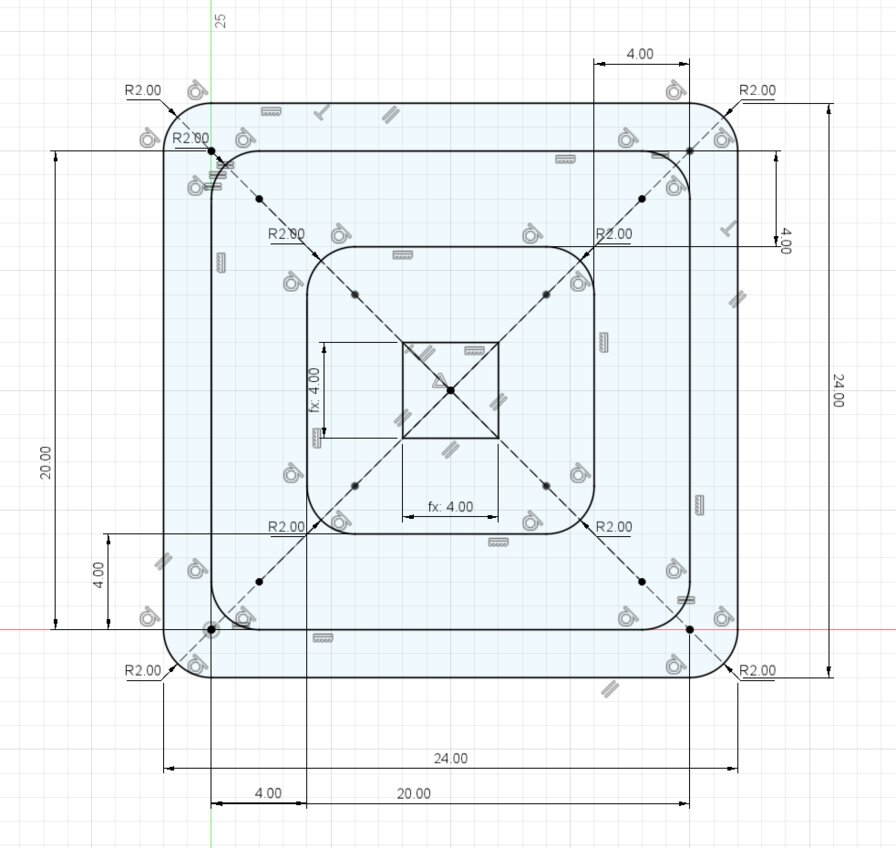
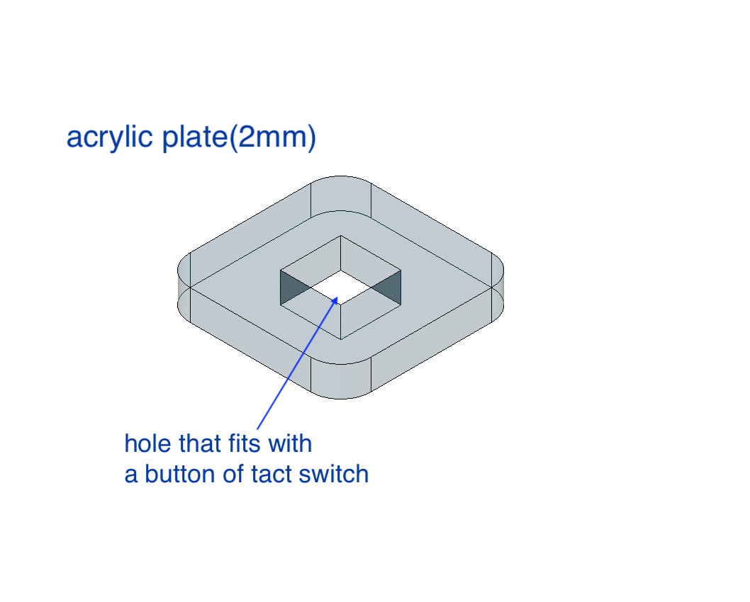
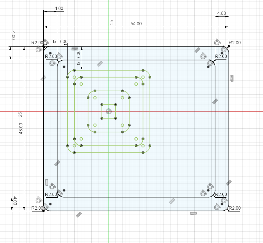
I started from "pad" as a cover of tact switch that I want to cast finally.
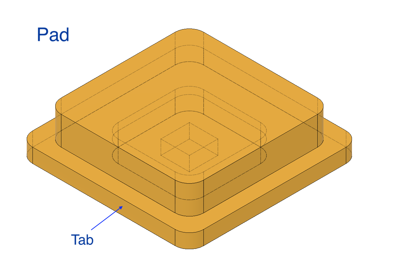
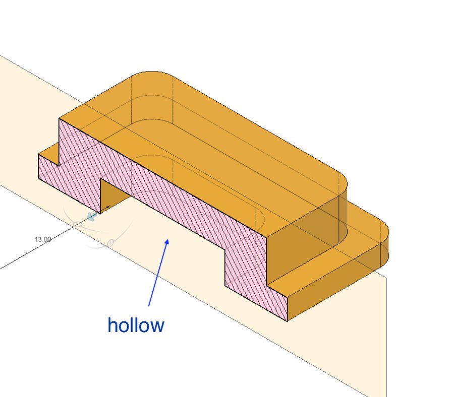
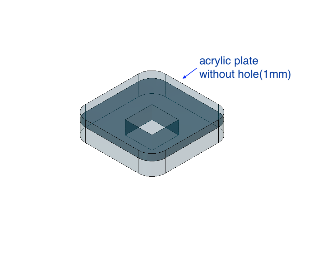
There is a hollow under the "pad". In this part, I will put the acrylic plate as a joint between "pad" and tact switch. This makes the whole button stable.
Tab of the edge at "pad" works as a hook underneth the cover surface of product and work as a stopper of the button.
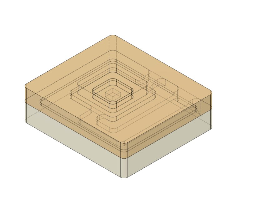
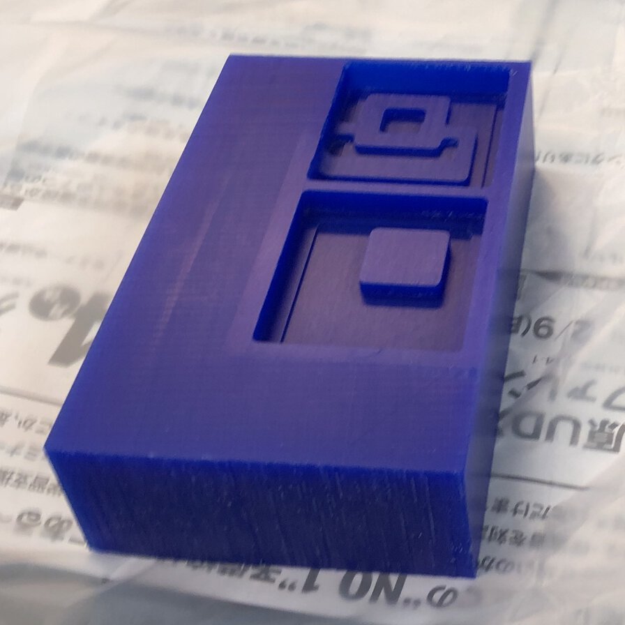
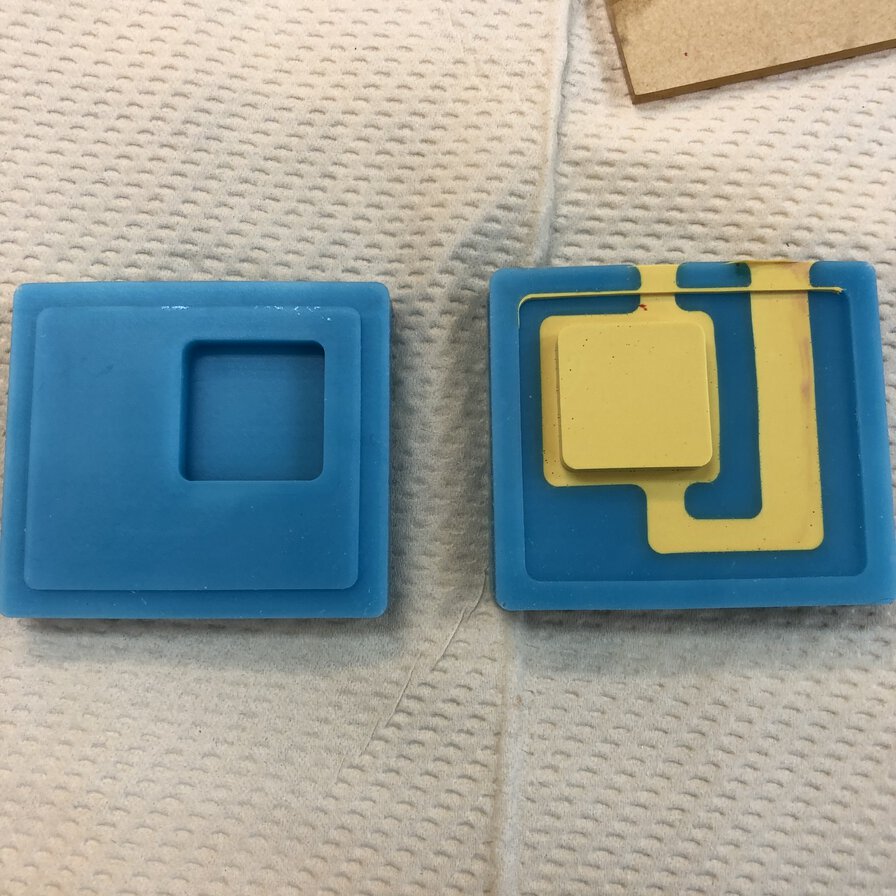
2 )Model: Mold
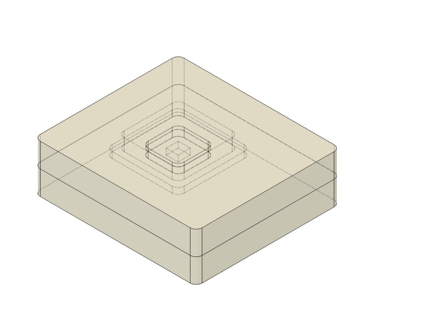
I made a mold in negative design by "pad" body. The mold needs to be two parts - top and bottom.
For designing tow parts of mold, I did:
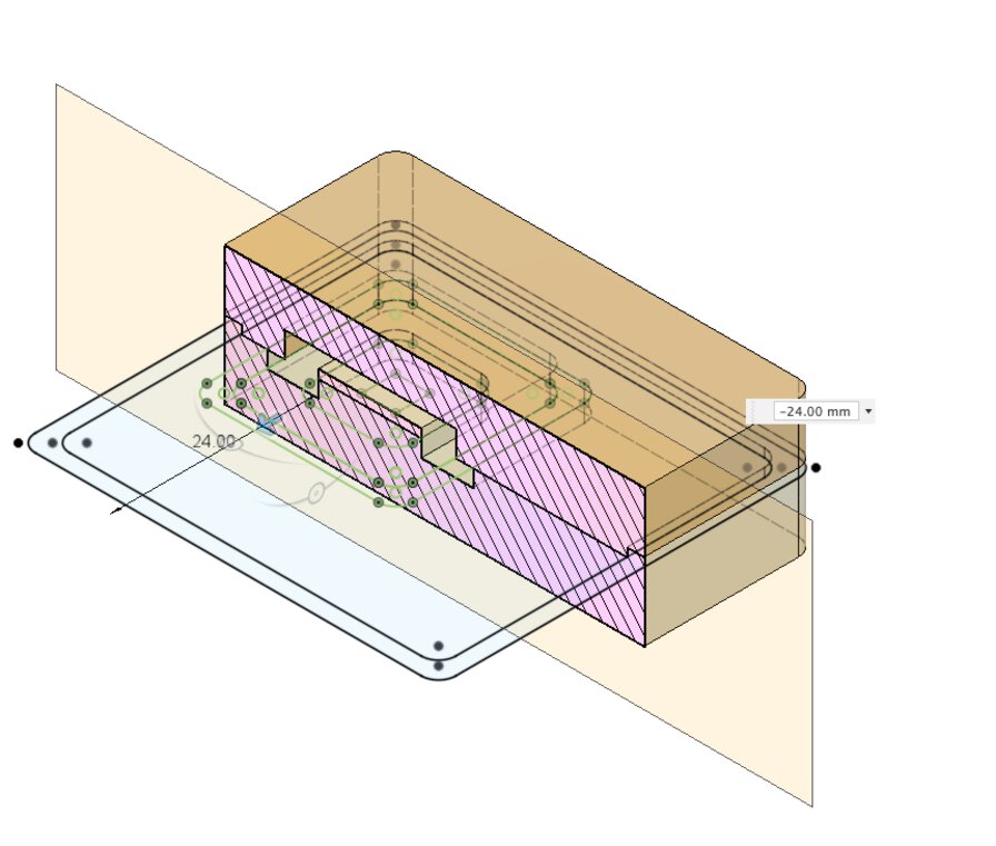
At first, I made the "bulge & hollow joint" too narrow. After some trials, I found that is too narrow as a hollow for 1/8 inch endmill for rough cut.
So, I changed the "bulge & hollow joint" a little wider (4mm).
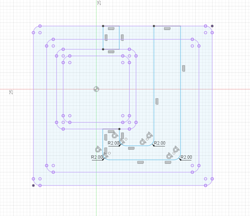
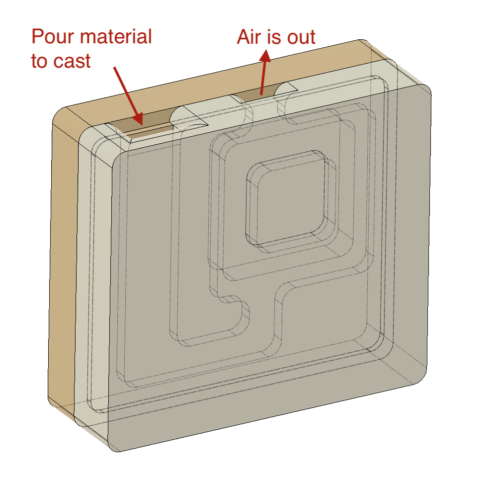
Then I made a sketch for making hole to dispent the material in and emit the air out
For pourint the material smoothly, I made fillet for the edges. This would also work for smooth cut path considering the kerf of endmill.
The cast material will be a little sticky like "honey in summer" according to Tamiya-san. This mold is small (the section of hole is 8mm square), so I might need to confirm whether it works.
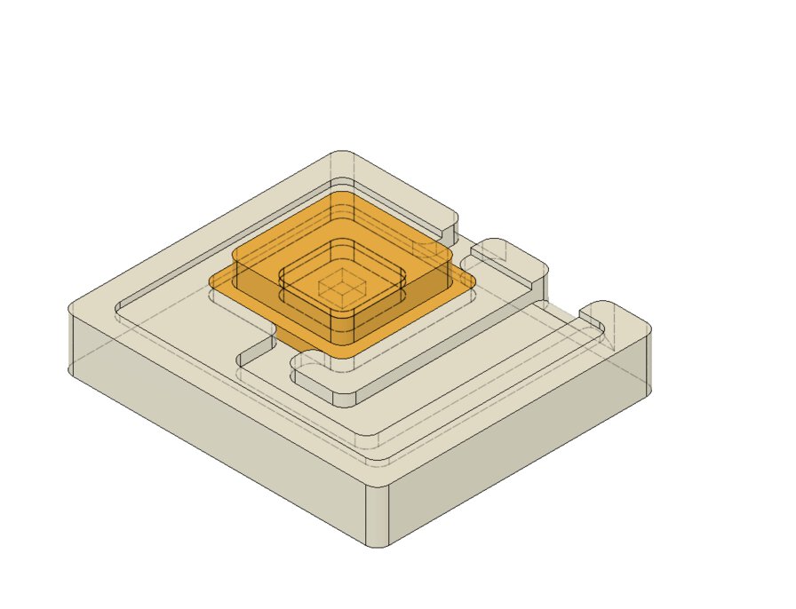
3) Model: Machinable Wax
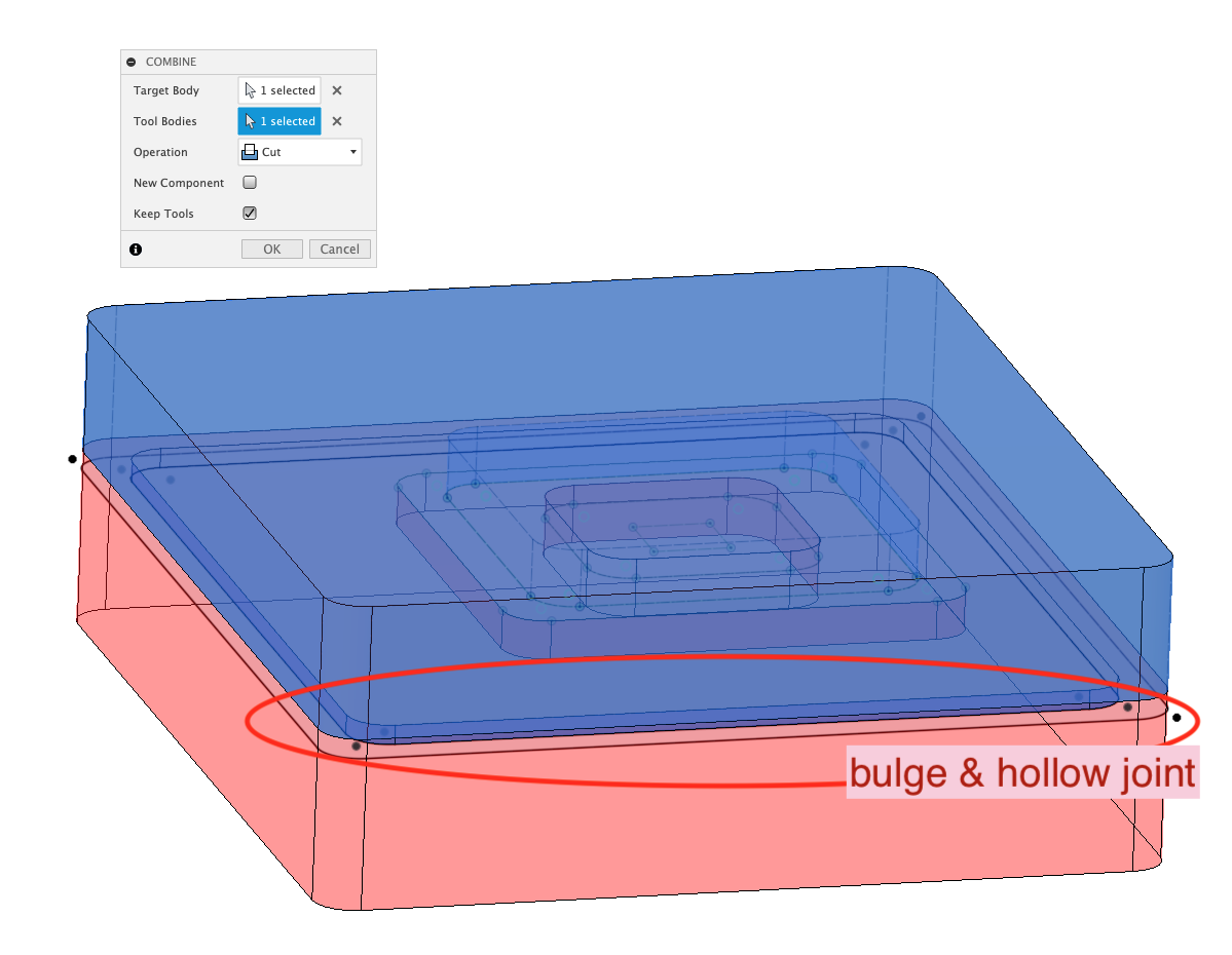
Flipped the mold design
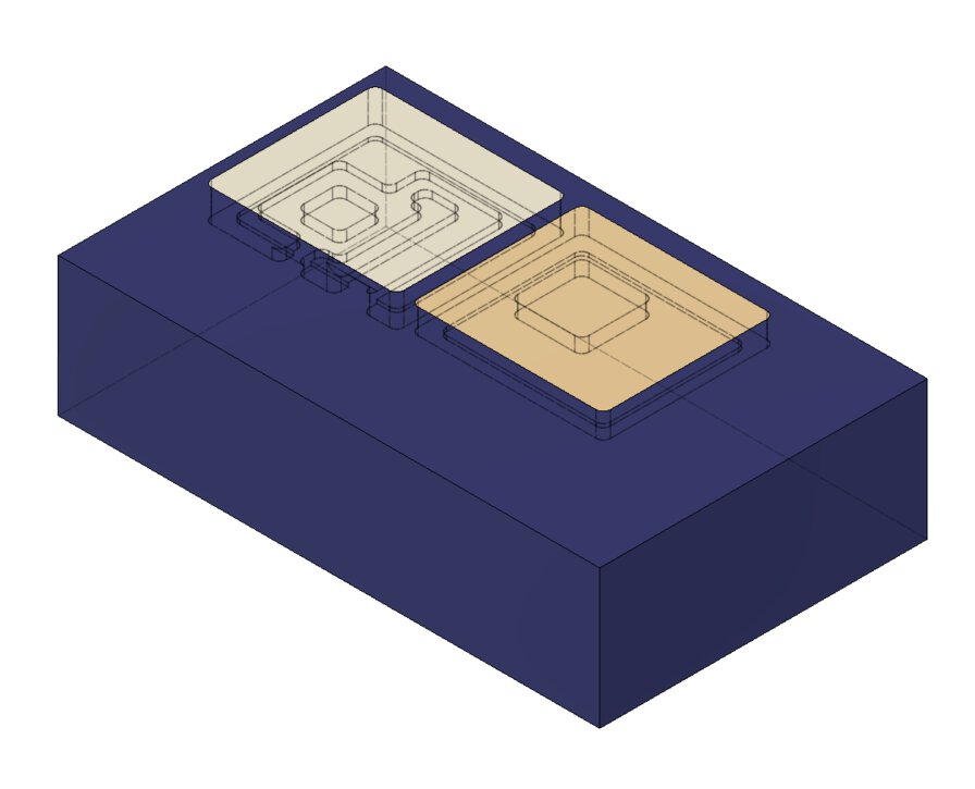
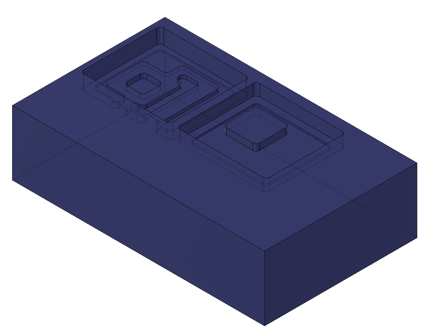
Made the wax design in negative by the mold design by "combine" by "cut" the target body and "keep tool" in Fusion 360.
Tool path
I made a tool path from cut wax model by MODELA player and checked the simulation result by Virtual MODELA player.
Setup CAM tool
I installed CAM Tool(Modela Player 4) and it's simulation viewer(Virtual MODELA) to Windows laptop PC.


At first, I tried to add tool by copying from defaut pre-set and change the diameter of tool. This failed because I did not set the machine as MDX-15 that I'll use at Kannai Lab

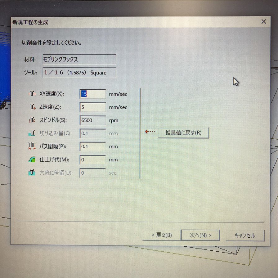
After I setup the machine as "MDX-15", I could setup tool for rough cut and finish cut. I will use the recommended parameters for the material of "modeling wax".


Tool for Rough Cut (Diameter: 1/8 Inch=3.175mm)


Tool for Finish Cut (Diameter: 1/16 Inch=1.5875mm)
Rough Cut


1. Select "modeling wax" as material

2. Select rough cut

3. Select cutting surface (top)

4. For rough cut, select 1/8 square (that I prepared preliminary)

5. Select partial area to cut

6. select "contour" and Up Cut

7. updated the values for rough cut
- XY speed: 15mm/sec
- Z speed: 1mm/sec
- Cut volume: 1 mm
- Path interval: 1.5mm

8. Name the task and made path immediately

My first rough cut path is over the edge of wax

Then I updated the selection to the cutting area again.

This time, the path it looks fine.
Finish Cut

1. Select "finish cut"

2. Use "1/16 Square" for finish cut

3. Select partial area to cut

4. select "scanning line" and select "X"

5. For finish cut, use recommended value that is configured as default value of MODELA player4.

6. Created finish cut path

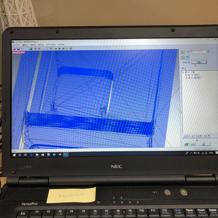
Simulated result (2D) is presented on Virtual MODELA

Simulated result (3D) is presented on Virtual MODELA
Milling wax as of 18 June
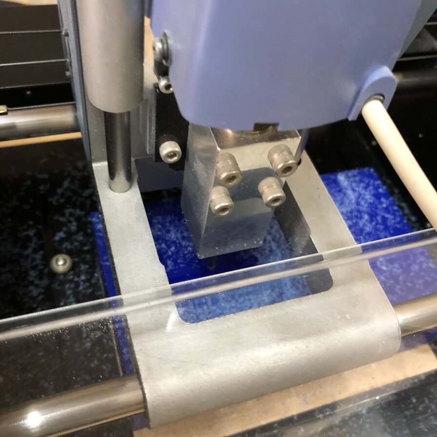
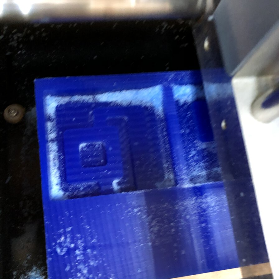
After coming back to lab from staying at home days under COVID-19, I went though physical work - milling wax, molding and casting.
Wax is Ferris File-A-Wax, Blue
Regarding material and safety information, please refer group assignment page.
Regarding milling wax, basically I followed what I simulated by Roland MODELA player 4 and Virtual MODELA at home. Following picture is what I did at lab differently from simulation.
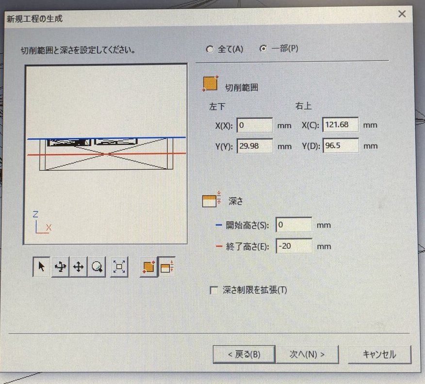
After checking the actual material, the size of wax is 87mm x 140mm (that is different from 92mm x 152mm in datasheet). I adjusted the cutting aria by setting X position as 0mm and dragging the top line (Y) to the edge of design.
Also, I set the height of finish as -20mm as my design is not deeper than 20mm.
I followed recommended value in MODELA player 4 at Fablab Kannai that is usually used in lab.
This is the cutpath of finish cut that I made by the cutting condition above.
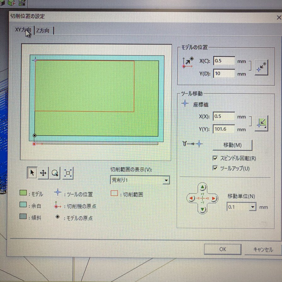
Though my model is made by the outline of 92mm x 152mm (in datasheet),I need to offest the postion slightly upper than default. I set the position of model as X: 0.5mm and Y: 10mm.
Milling wax 3D simulation - Roland Modela player 4
Cut wax by Roland MDX-15
Milling wax 3D simulation - Roland Modela player 4
Molding
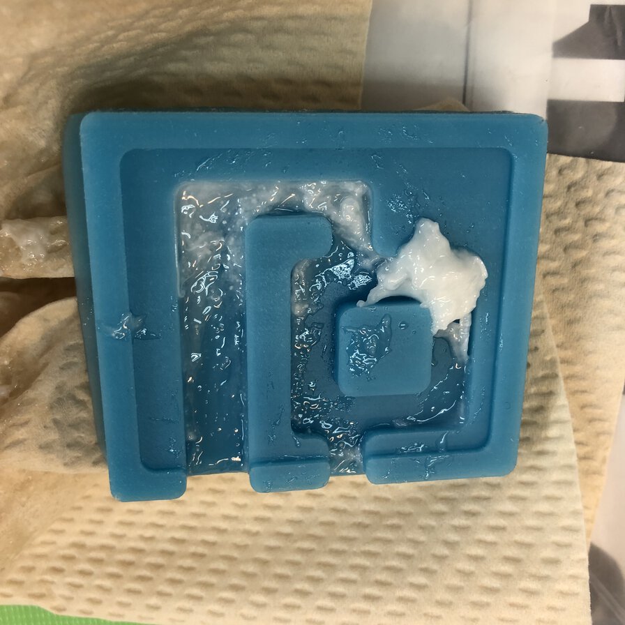
Cleaned up wax after milling. The surface is very smooth after finish cut.
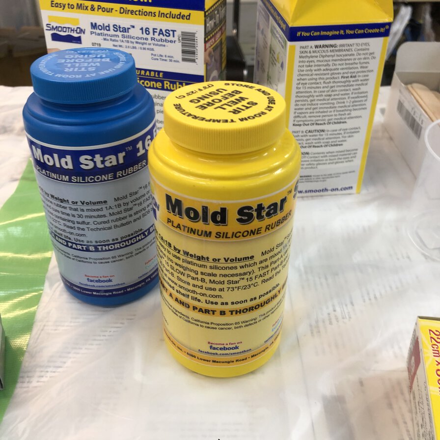
I used Smooth-on MOLD STAR 16 FAST.
Regarding material and safety information, please refer group assignment page.
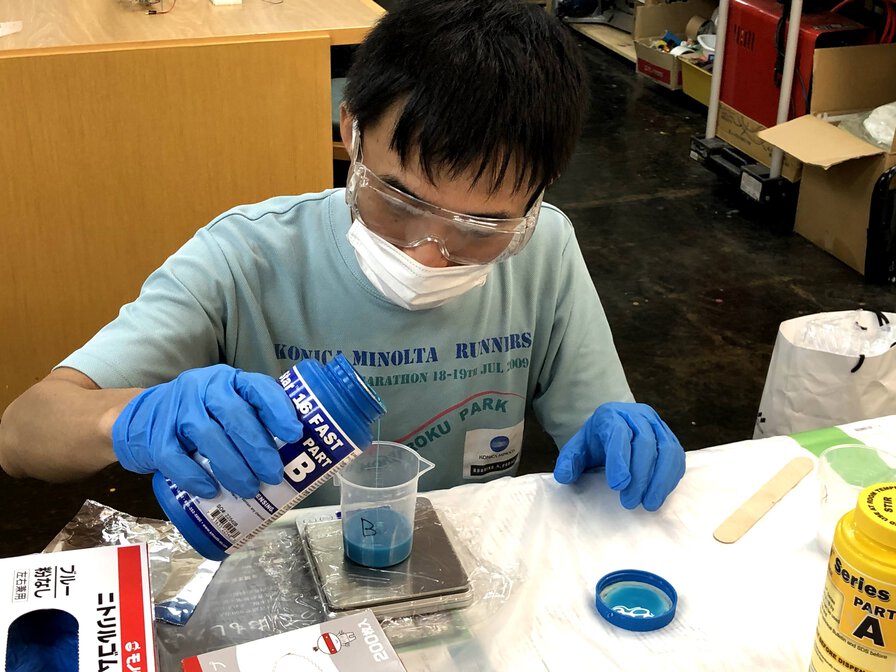
Dispenting materials carefully wearing gloves, mask and protection glasses.
We covered working desk by newspaper and vinyl sheet for avoiding sticky silicon to put on the working place
It would be better to cover my arm by long shirts actually
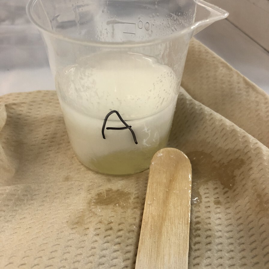
Material A:B is mixed by ratio of volume=1:1 and weight=1:1
Pot life is 6 minutes.
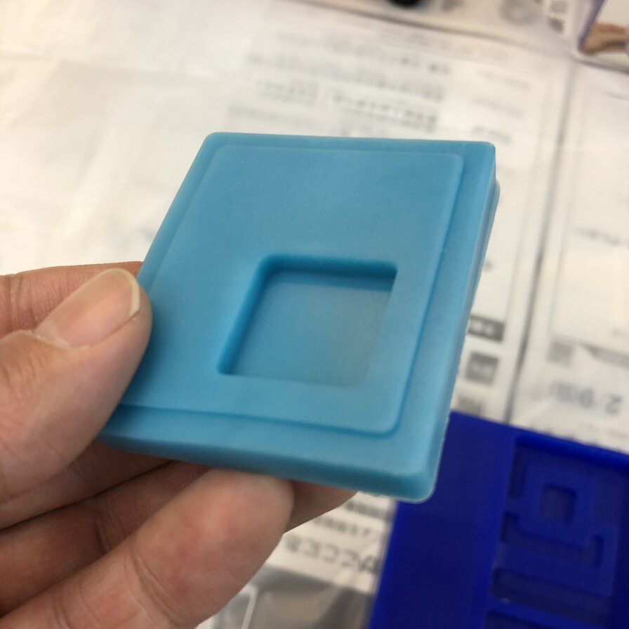
After 30 mintues of cure time, the material was fixed successfully.
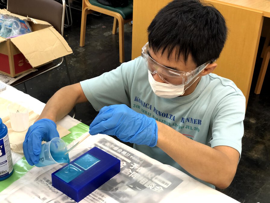
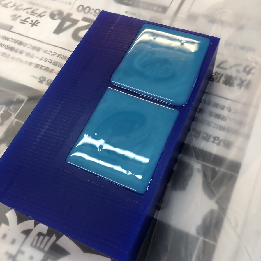
Casting
I used Smooth-on Smooth-Cast 300.
Regarding material and safety information, please refer group assignment page.
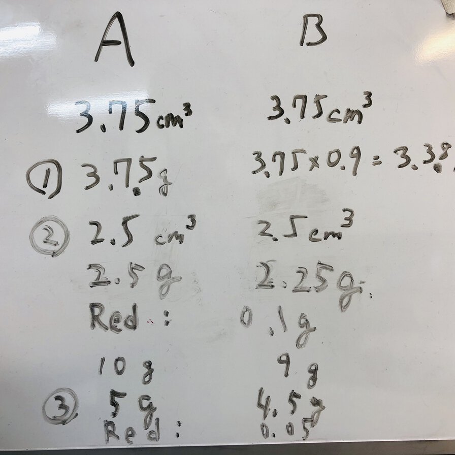
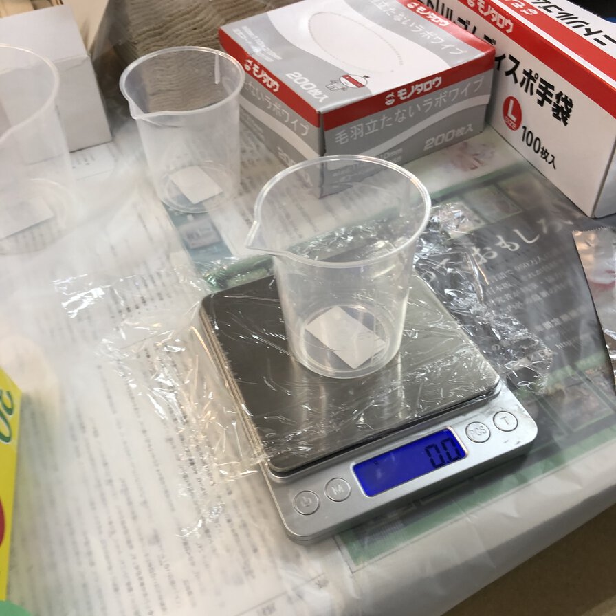
As this materials mix ratio of weight is 100(A):90(B) and coloring material needs to be in 0.1%-3% of total weight, I checked the weight by digital scale(volume ratio is the same but it was difficult for me to measure the volume for each material by beaker as I worked on very small sized casting)
For casting, I had 2 kinds of errors.
The 1st error is "not enough mixing" materials". When I dispent the casting material at first time, even 20 minitues ( 2 times longer than 10 minutes of cure time) passed, the silicon was not fixed.
It seems to be caused by too short time to mix materials. After I mixed materials sufficiently, it resulted in fixing as expected.
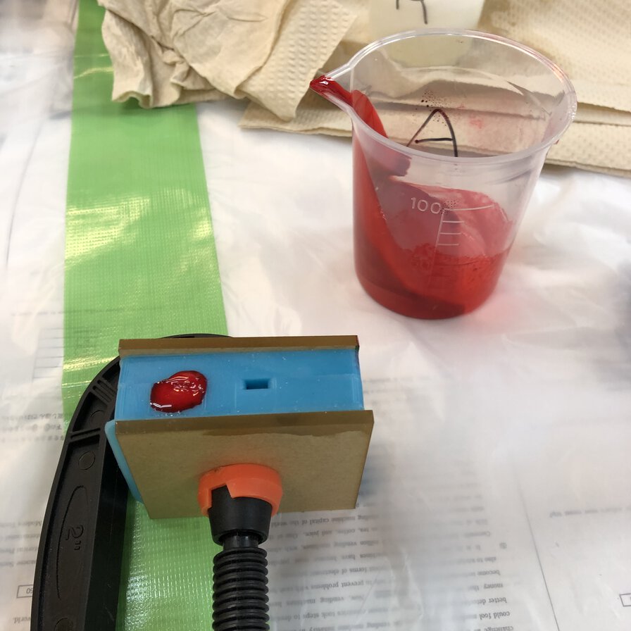
Without color, it's difficult to check the mixing status by sight. Putting color to material "B" and mix it to A (following guidance of Smooth Cast) helps to check the mixing status.
The second error is "delay to dispent the cast material". As the material pot life is short as 3 minutes and throat of my mold is narrow, I needed to dispent it quickly before the mixed material get fixed.
Tamiya-san checked my "sprint time" to dispent the material by stop watch. After I get accustomed to the work and complete mixing A & B and dispenting it under 2 or 2 and a half minutes, it went well.
I put color to cast materials by Liquid Urethane Colorarants.
Regarding material and safety information, please refer group assignment page.
including coloring process, I went thorugh following process.
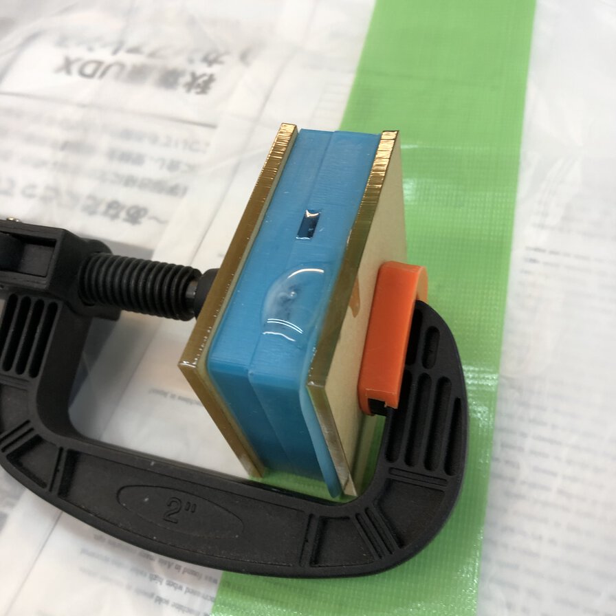
- Fix a mold silicon by clamp (adjust the edge parts as a registration key)
- Setup beakers and write "A" or "B" by magic penfor clarification
- Dispent and measure 5g of "A" by digital scale
- Dispent and measure 4.5g of "B" by digital scale
- Drop color 3 or 4 times of color 1 (e.g. yellow or blue) to material "B" (It's because too tiny amount of colorant cannot be measured by digital scale at lab)
- Drop color 3 or 4 times of color 1 (e.g. white) to material "B"
- Mix thoroughly colors in material "B"
- Dispent "A" to "B"(8.) and mix total materials thoroughly
- Dispent total material(9.) to mold. It's necessary to complete the work from 8. to 9. in 3 minutes of pot life
- Wait 13 minutes(pot life(3 minutes) and cured time(10 minutes)) from 8. until getting the urethane material cast by mold.
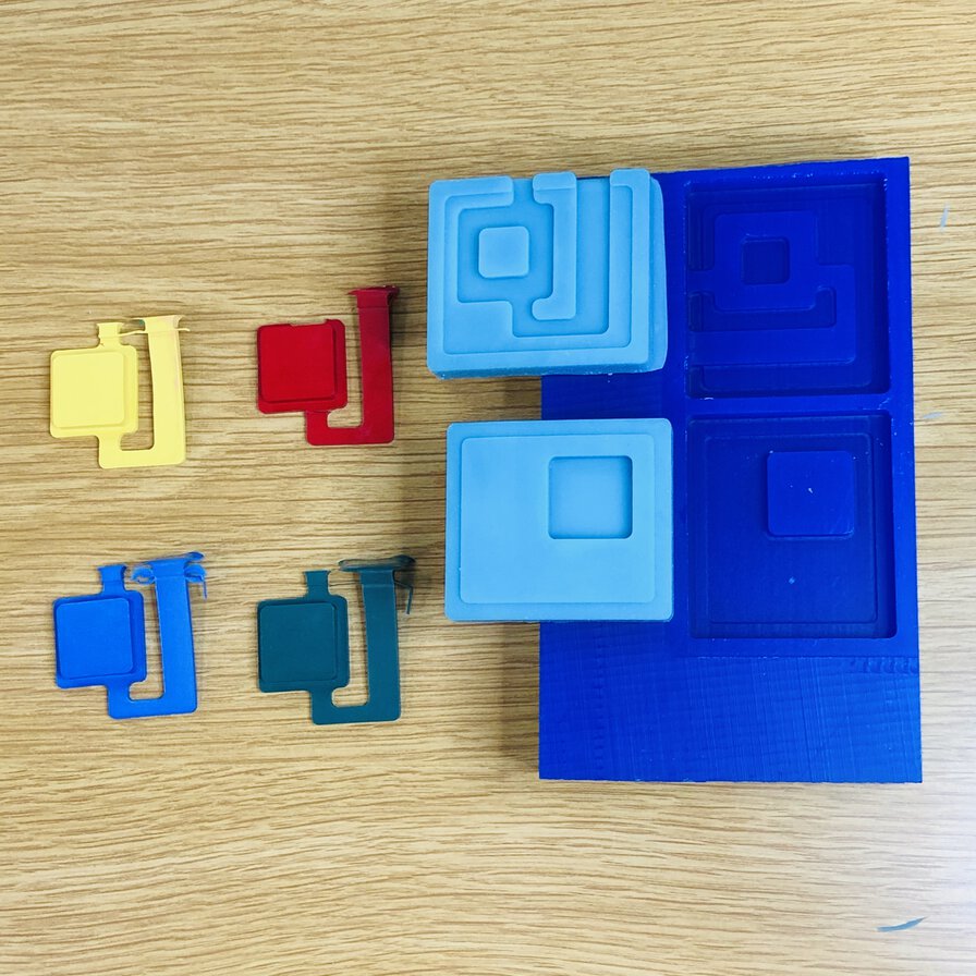
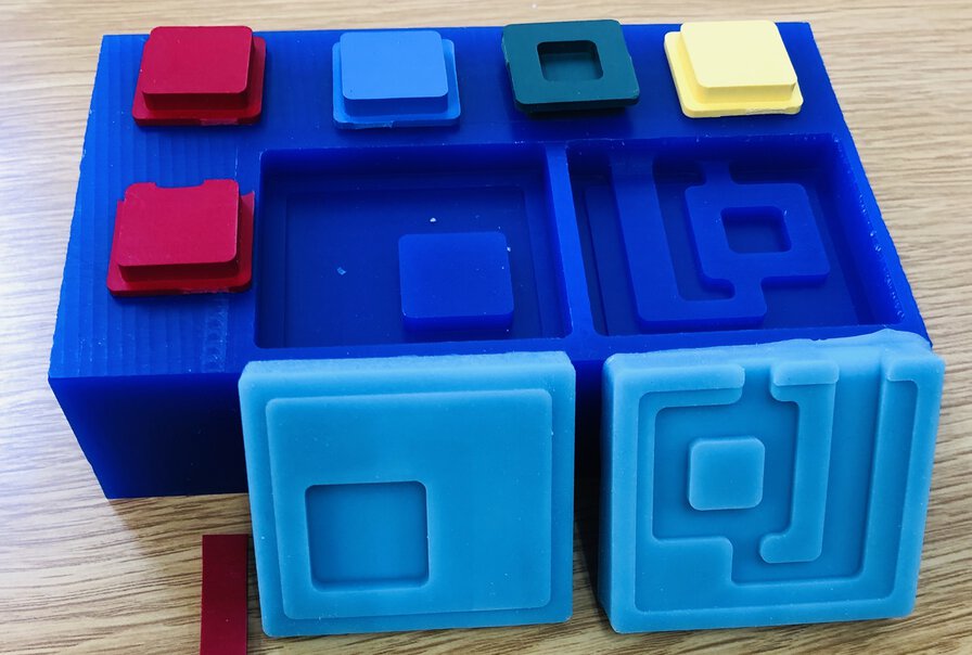
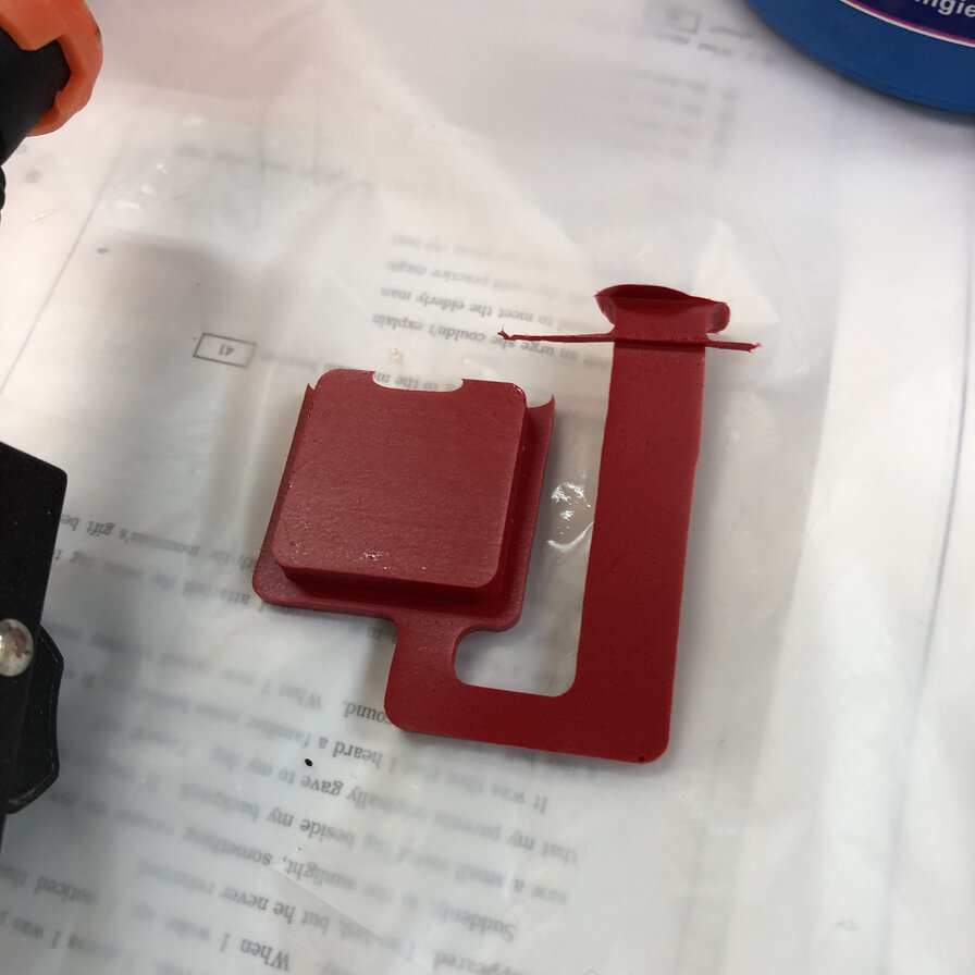
I made following colors of pad cover in tactile switch that I'll used in my final project.
- Red
- Sky blue(blue + white)
- Green
- Mastered color (yellow + white)
Lessons Learned
- "Mold" is a negative shape to make cast as a master. "Cast" is copies of the positive shape made by "mold". It's simple concept but require process to be considered well.
- It's very important to understand the tools and materials(for example, consider diameter of the mill(rough cut is 1/8=3.73mm) and cut depth that depends on the length of mills and collet height)
- There should not be undercut for design of the mold. Otherwise, we cannot pull off the mold by hand.
- For making 2 parts mold, it's important to make registration keys to fix the joint between parts of mold.
References
- Milling machine: Roland MDX-15
- Endmill (Ref: Carbide Depot
- CAM software: MODELA player 4
- Simulator: Virtual MODELA
- Caribde Depot (End mill catalogue)
- Ferris File-A-Wax, Blue
- Ferris File-A-Wax, Blue - Safety Data Sheet & Technical Data Sheet
- Smooth-on MOLD STAR 16 FAST
- Smooth-on Smooth-Cast 300
- Liquid urethane colorants
- Roland Modela player 4 - Instruction page by Yuichi Tamiya
- Molding and Casting lecture for Fab Academy 2020 (shanhai, Saverio)
Files
- 3D models for pad, cast and mold : link to Autodesk A360, f3d
- STL file for wax : wax.stl
- Tool path - an exported file from MODELA player : wax.mdt