Electronic Design
Regarding the electronics of my machine I decided to be as efficient as possible, meaning if a componant is cheaper to make it on my own I make it, If otherwise I buy it.
First design
Following this approach I decided to make a microcontroller board and a distribution board but buy the stepper drivers. The microcontroller board is a slightly compact version of SatshaKit and the Stepper drivers are A4988 . I used Eagle to design the PCBs .
Microcontroller board
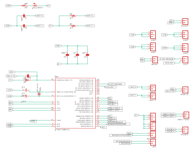
I used the original Satshakit schematic, since I'm going to use just 2 axes, I eliminated some pins connected to the z-axis and other pins and added a small circuit for the soleniode and for the sensor.
Distribution board
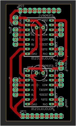
I started by drawing the schematic, this board is designed to support two A4988 stepper driver. It is designed to prevent the microcontroller board from being a bit complicated.

Final design
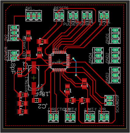
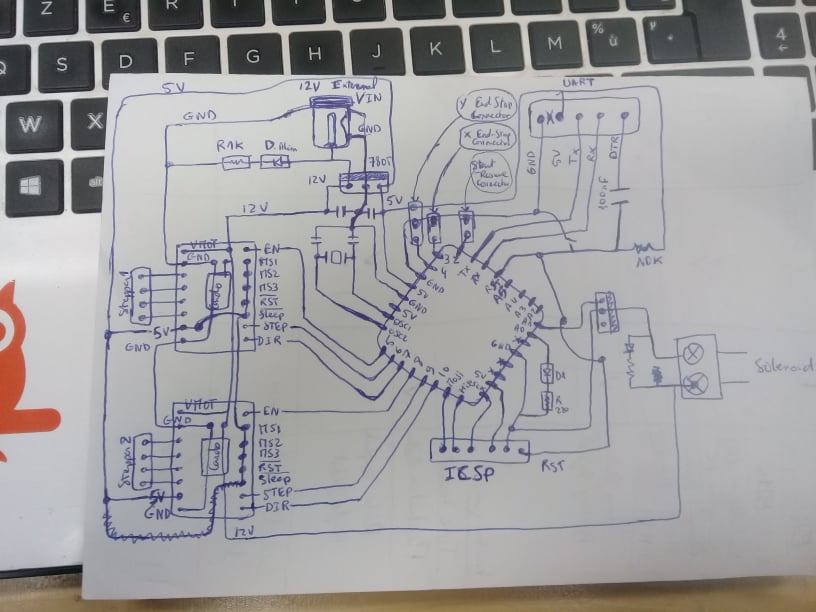
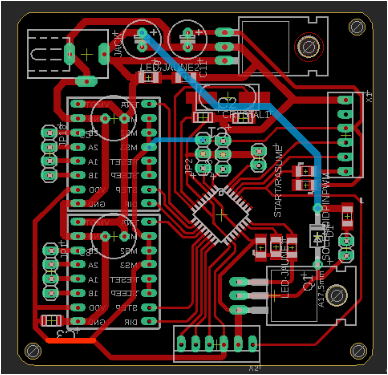
Following the same approach tried to combine the two boards on one to compact the volume of my machine. This final board contains the two steper drivers as well as the microcontroller, pins for the two sensors "END_STOP_X" and "END_STOP_Y" , 2 pins for start/resume and 2pins for the solenoid.
I started by drawing the diagram on a paper, it helps me a lot in the routing phase...
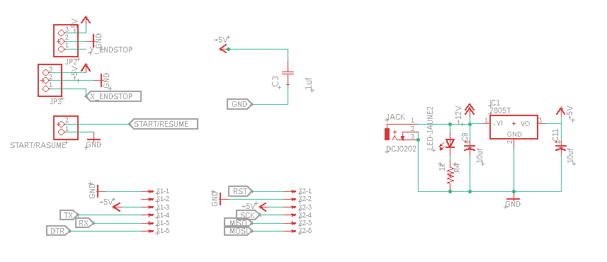
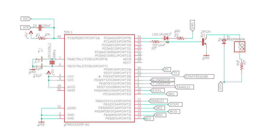
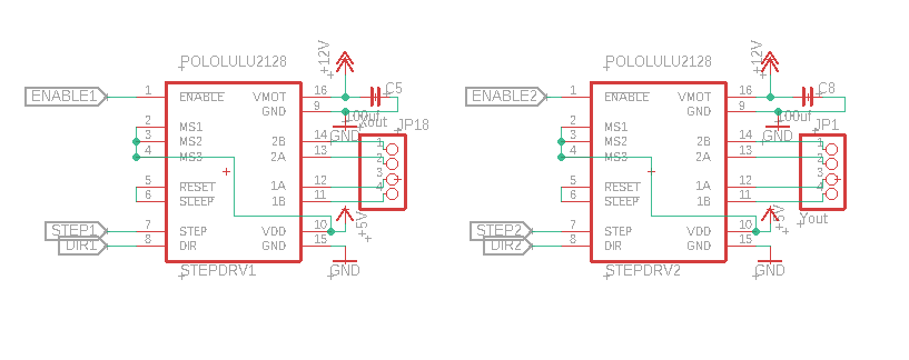
Then I drew the schematic of the board on eagle
I routed the board and this is how It looked
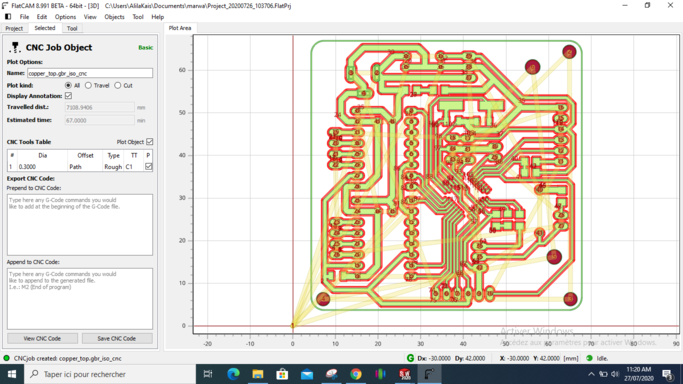
Then I used FlatCAM to generate the Gcode for the cnc machine and I use a mini CNC to mill the board
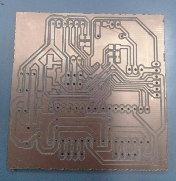
This is how the boards looked after milling
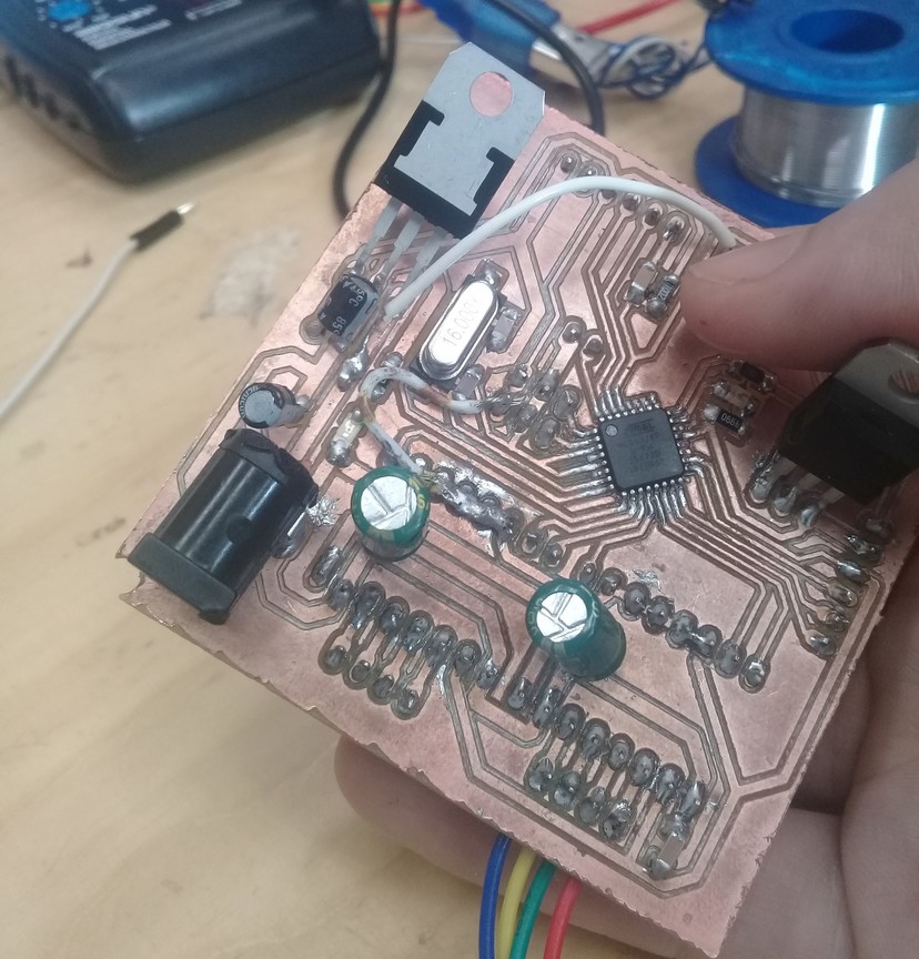
Soldering is not easy since my board was small but here it is after soldering.
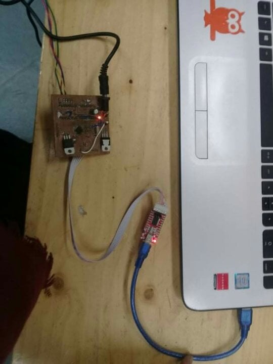
After soldering the board, I wanted to test and see if my soldering and connection are okey or not. Like in electronic production week, I used Arduino as ISP to program the board. I burned the boot loader successfully, and it was a promising start.
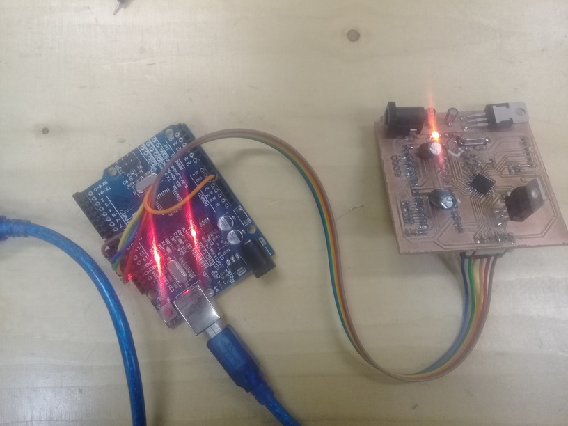
After that I used an FTDI programmer to comunicate with the board via serial communiction and test the motors and the sensors. I connect :
DTR –> DTR
RX –> TX
TX –> RX
Vcc –> Vcc
Cts (Not connected)
GND –> GND