Final project progress
- 1. Computer Aided Design CAD
- 2. Computer Controlled Cutting
- 3. 3D Scanning and Printing
- 4. Electronics Design
- 5. Ouput Devices
- 6. Electronics Production
- 7. Programming
- 8. Interface and Application Programming
- 9. Networking and Communications
- 10. Bill Of Materials
- 11. Files
Computer Aided Design CAD
Introduction
For my final project, I decided to make a wall hanged interactive world map. I have been always fascinated by the idea of being a traveler, and I love buying map related merchandise. And since I wanted to make for my final project something I am passionate about, I think this might be the best idea.
But considering the current global situation, and the lack of accesses to the lab, and the fact that I adopt this idea little bit late, I decided to narrow the scope of the project and make it a certain region from the world, and after the graduation I will get back to it and make my dream come true, hopefully.
So, my project will be an interactive Arab world map, that should be used as an interior decoration masterpiece with some features like lighting up each country area, interactive voice with some brief about the country.
Concept Generation
The first step was the hardware concept generation, I had to decide the scale, shape, joints and many other things in the hardware design to make it as what I have dreamed of.
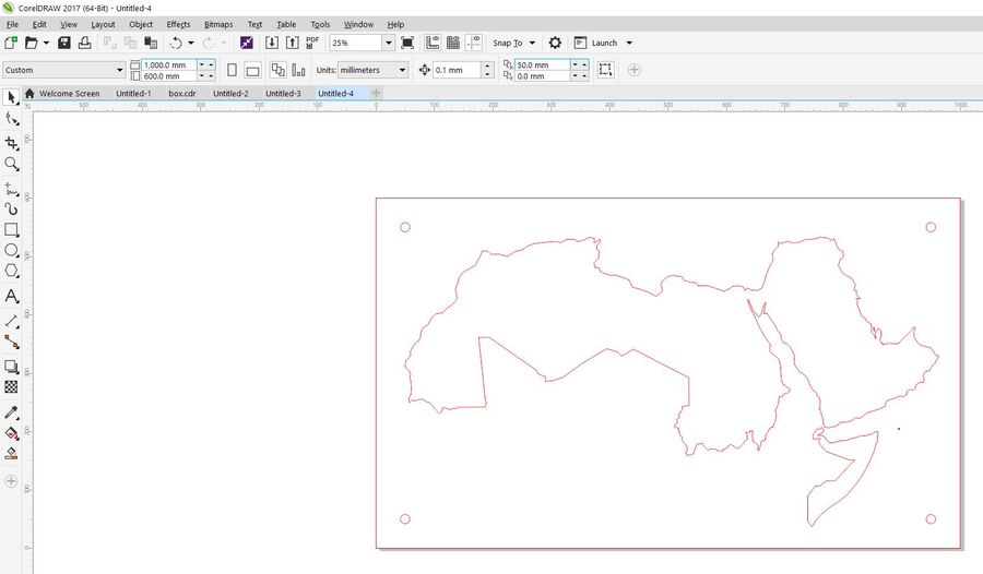
Since it will be a wall hanged decorative object, and because I’m planning to make it using the laser cutting machine, I decided to set the size 100*60 cm. fortunately, the ratio of the Arab world map fits perfectly in that scale.
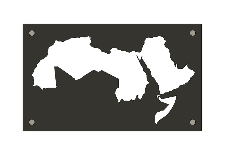
For the shape, it will be like any other regular wall map, rectangular dark frame around the white land boarders.
I don’t think that I will use joints to connect the layers of the map itself, the adhesive will be enough. And to hang it in the wall I will use four large mounting screws.
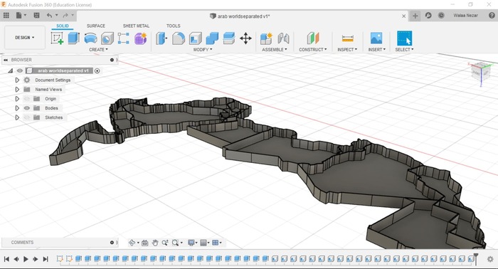
3D Design
To have a visualized version of my project I started designing it using Fusion 360 software, I downloaded a SVG file for the Arab world map, and extruded each country as a new body.
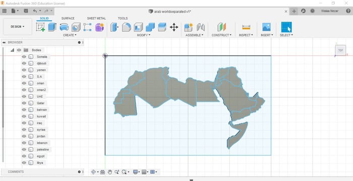
After that I created a shell of thickness 2mm for each county, to create 4mm thickness boarders between each closed area (country).
This boards will be covered by the front layer which contains black and white acrylic snapped together. The white acrylic will be in front of the land area and the black will be in the surrounding areas.
Computer Controlled Cutting
Materials to Cut
I used 3mm white and black acrylic boards for the front layer of the map, and for the back I used a 3mm black acrylic too.
Cut files
As I mentioned before, I will make the front layer and the pegboard using the laser cutter to cut them to the shape I designed. To do that I exported the sketches from fusion 360 as DXF filesand cut them using the laser cutting machine as shown below.
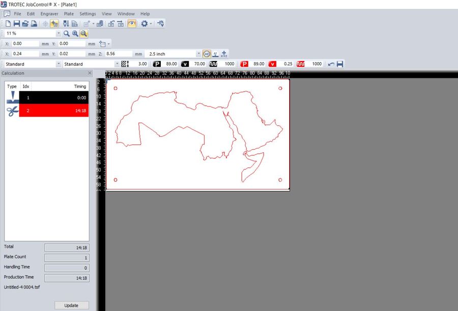
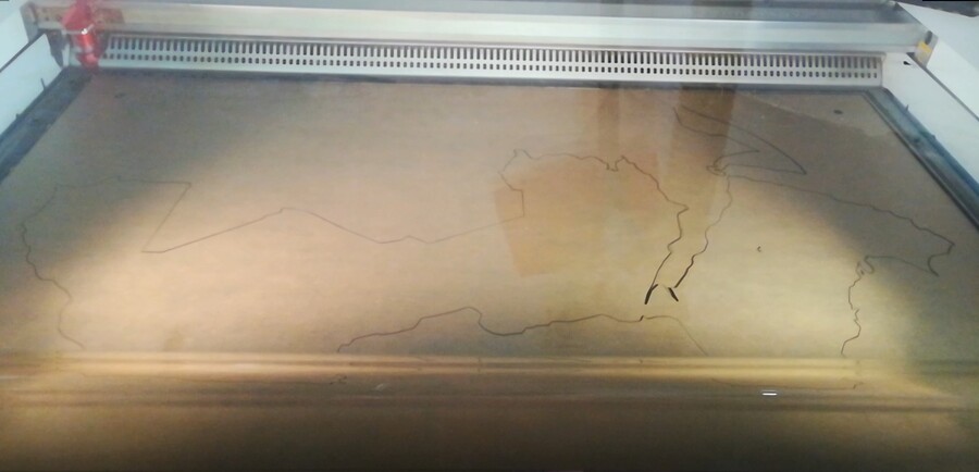
For the cutting I used the acrylic cutting settings, speed .25 power 89 frequency 1000 .
And for the engrave I used speed 70 power 89 frequency 1000 .
3D Scanning and Printing
Boarders Walls
For the middle layer that separates the front from the pegboard, it contains only thin lines represents the boarders wall between the countries. I needed this layer to keep the light concentrated inside each area and have a brighter look.
But to decide the exact height of this layer, I needed to test the LEDs to figure out the best distance between the LEDs and the front acrylic that gives me the better light diffusion, because I don’t want the LEDs to look like small dots from the front, I want it to have a smooth clean lighting for the full area.
I tested this distance in the lab, trying to make the LEDs defuses homogeneously. The result was about 3cm. so I decided 3D print boarders separated and glue the parts together.
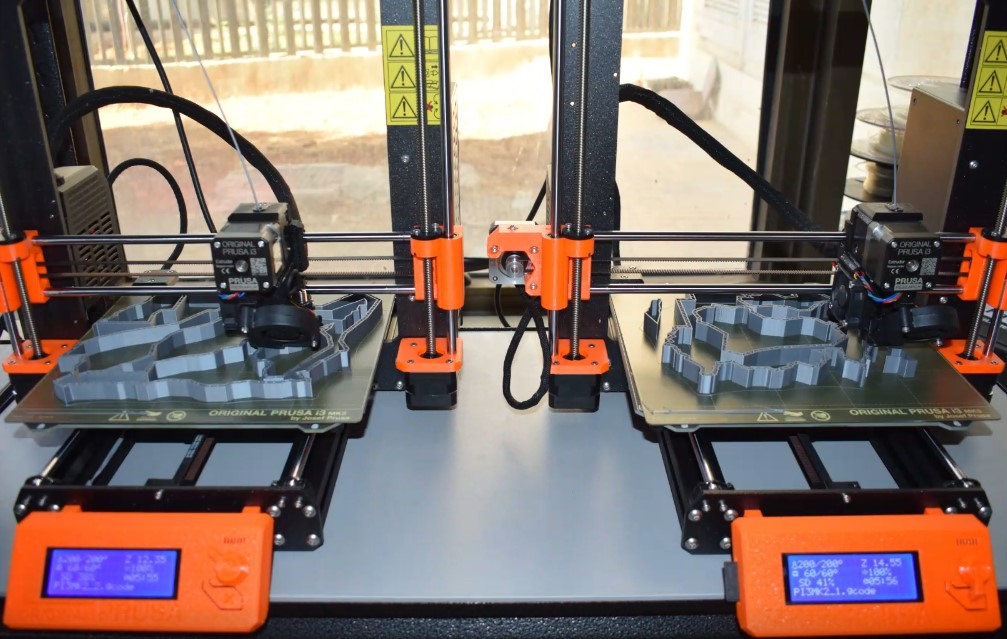
I started with the 3D design and exported the bodies as STL , then imported them to the Cura slicer. I tried to distribute the bodies to the minimum number of printers to make the process easer. i was able to distribute them to 4 print files, which was not bad, but i used two printers to finish faster. See below the cura images.
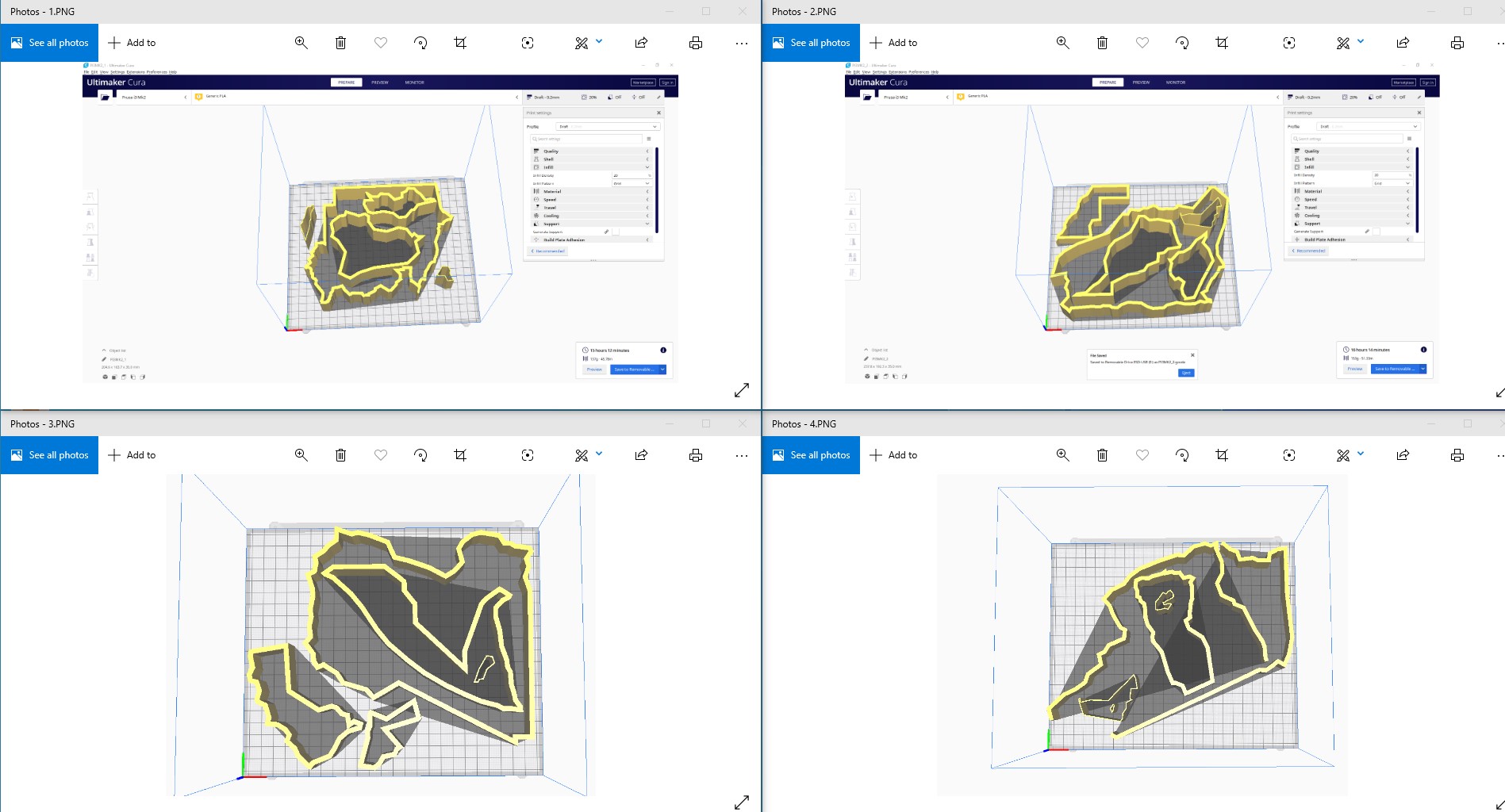
printed them using Prusa mk2, it’s really a powerful machine. I used the layer height to be 0.2 mm since the finish was not critical for me, the infill density 20%, speed 60, and without any support or build plate adhesion.
I glued all countries to gather as seen below.
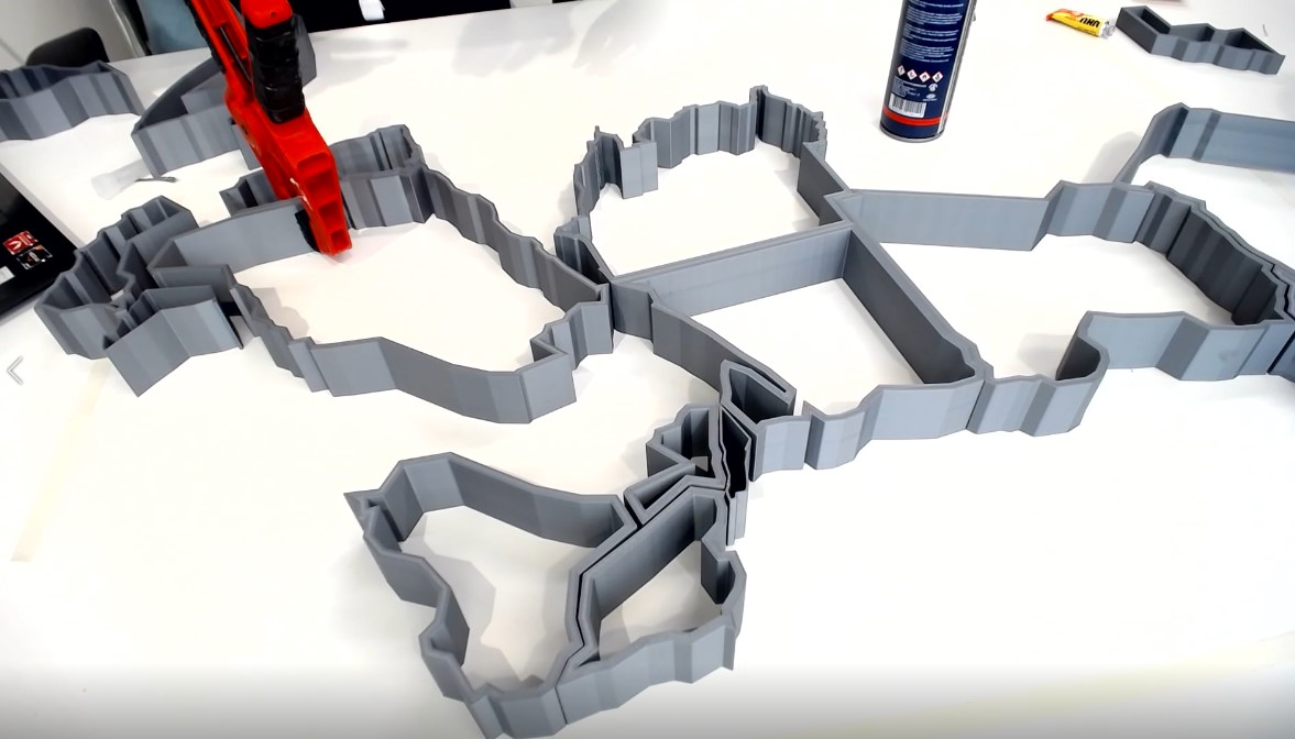 gluing
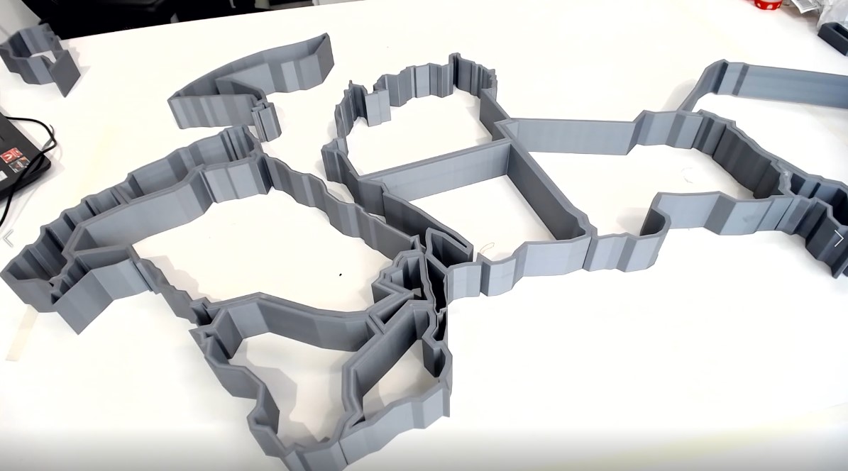 resulted boarders
Electronics Design
PCB Design
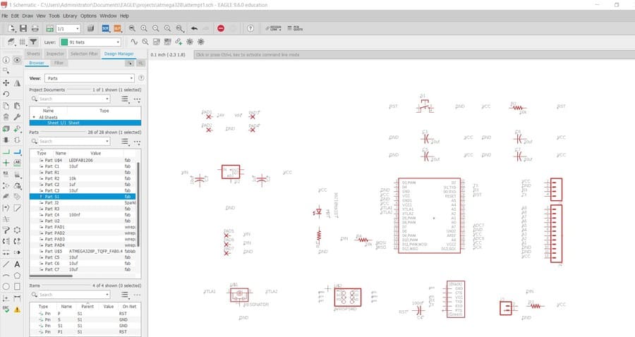
This stage was the scariest thing for me, I delayed it for more than 3 weeks, But I had to face it after all. I started with a meeting with Eng. Yazan who’s the electronics engineer in the lab, he helped me recognizing what I have to do first and how to do it. So I started gathering all the components I needed for the PCB that will control my LEDs panel in eagle schematic workspace.
PCB Components
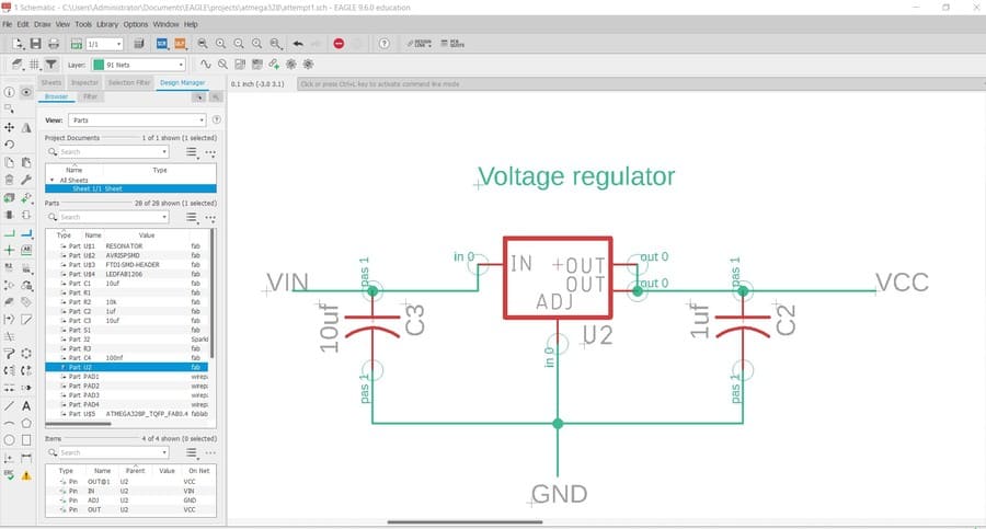
the exact objective of this PCB is to control the LEDs lightning depending on the instructions given to them by the Arduino code. the 5 volt should inter to power the microcontroller and the surrounding components, so we needed the voltage regulator to control the flow of these 5 volt to protect the components from overloads.
In the image below, the VIN is the power coming from the power supply and VCC is the output voltage from the regulator.
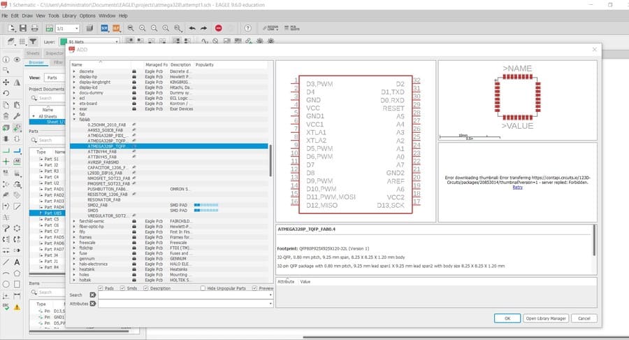
I used the Atmega 328p as the microcontroller for this project, since it available at the lab and has the desired number of pins I need. I selected it from the Fab Lab library created by Eng.Yazan.
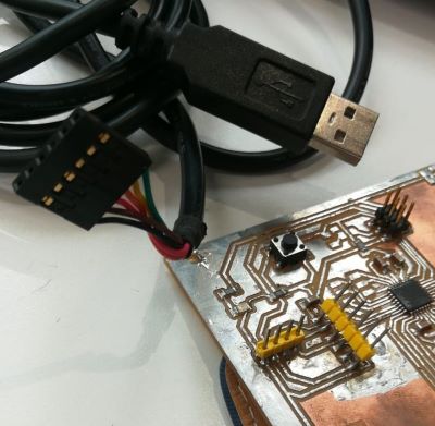
To be able to program the microcontrol, I used ISP as in the electronics design week, and FTDI for serial communications. connected them to the Atmega 328p as shown below.
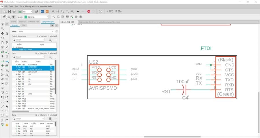
to filter undesired noise from power supplies, I used decoupling capacitor at each VCC pin in the microcontroller. These capacitors should be close physically to the microcontroller, and each of one connected directly to a VCC pin.
To reset the board any time I may need, I used a reset button connected to a pull-up resistor.
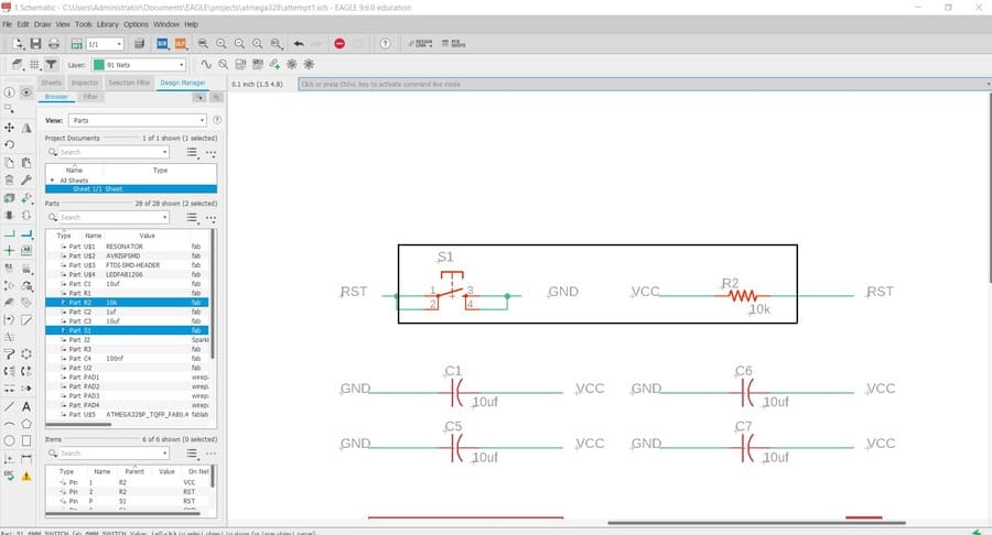
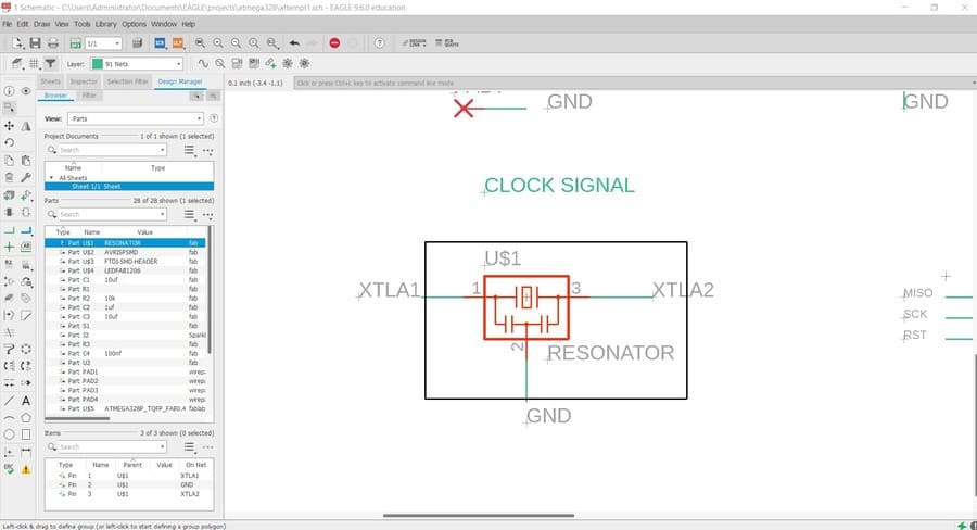
And of course we need something to drive the microcontroller, which means I should connect a clock signal (everything happens inside the microcontroller is based on this clock signal). The Atmega 328p do have a built in oscillator to generate the clock signal but it could be considered slow and it’s not accurate. External clocks in the other hand can run almost any speed we want and much higher accuracy. So I added a16 MHz resonator to my schematic as shown below.
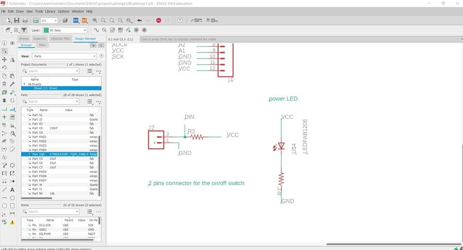
And I added a power indicator LED and resistor, also I added some pads for the LEDs wires and the ON/OFF external switch.
For the power supply, I had to calculate the power needed depending on the amount of current that the LEDs will draw. Since I will use 160 LED each one of them needs 60 mA (20 mA for each color from RGB in its max brightness from the data sheet), so I will need 160*60 = 9600 mA which means 9.6 A. this current is the max amount will be drawn by the LEDs if they all lightened up together with their max brightness.
The power equals the voltage multiplied by the current, so it equals 5 volt* 9.6 A = 48,000 watt ( 48 KW) as a max power needed.
in the lab I couldn’t find a 5volt, 48 KW power supply. so I had to use the 24 volt, 48 KW power supply and use a buck converter with it, to convert the 24 volt from the power supply to a 5-volt interring the LEDs, and the voltage regulator and then from it to the microcontroller and the components.
The buck converter concept is pretty cool; it uses a switching concept to decrease the input DC to a smaller output DC. below paragraph from Wikipedia best explains this concept.
“Beginning with the switch open (off-state), the current in the circuit is zero. When the switch is first closed (on-state), the current will begin to increase, and the inductor will produce an opposing voltage across its terminals in response to the changing current. This voltage drop counteracts the voltage of the source and therefore reduces the net voltage across the load. Over time, the rate of change of current decreases, and the voltage across the inductor also then decreases, increasing the voltage at the load. During this time, the inductor stores energy in the form of a magnetic field. If the switch is opened while the current is still changing, then there will always be a voltage drop across the inductor, so the net voltage at the load will always be less than the input voltage source. When the switch is opened again (off-state), the voltage source will be removed from the circuit, and the current will decrease. The decreasing current will produce a voltage drop across the inductor (opposite to the drop at on-state), and now the inductor becomes a Current Source. The stored energy in the inductor's magnetic field supports the current flow through the load. This current, flowing while the input voltage source is disconnected, when concatenated with the current flowing during on-state, totals to current greater than the average input current (being zero during off-state). The "increase" in average current makes up for the reduction in voltage, and ideally preserves the power provided to the load. During the off-state, the inductor is discharging its stored energy into the rest of the circuit. If the switch is closed again before the inductor fully discharges (on-state), the voltage at the load will always be greater than zero.”
And below video shows this process briefly.
VideoExternal Boards
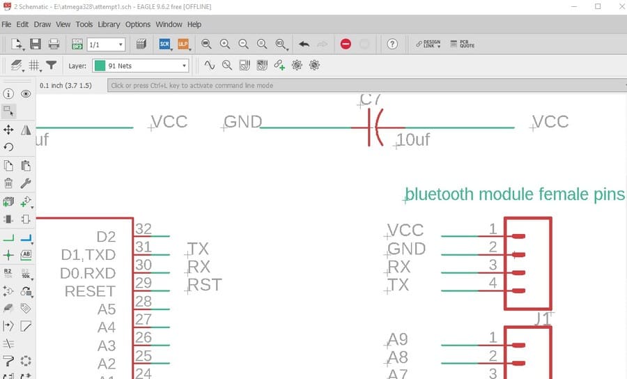
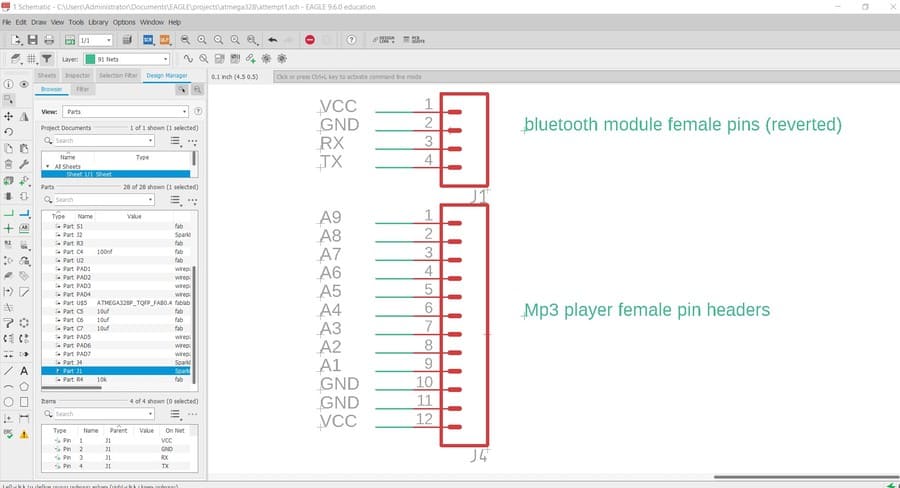
In addition to the power supply, I will be using 3 external boards with my PCB, the first is the buck converter, I explained the need of it above. The second board is the Bluetooth module which I needed to facilitate the communication between the board and the mobile application. Its connection is very easy, I used it before in the Networking and communications week, it has 4 pins only, so I added 4 pin header and connected to the microcontroller as shown below.
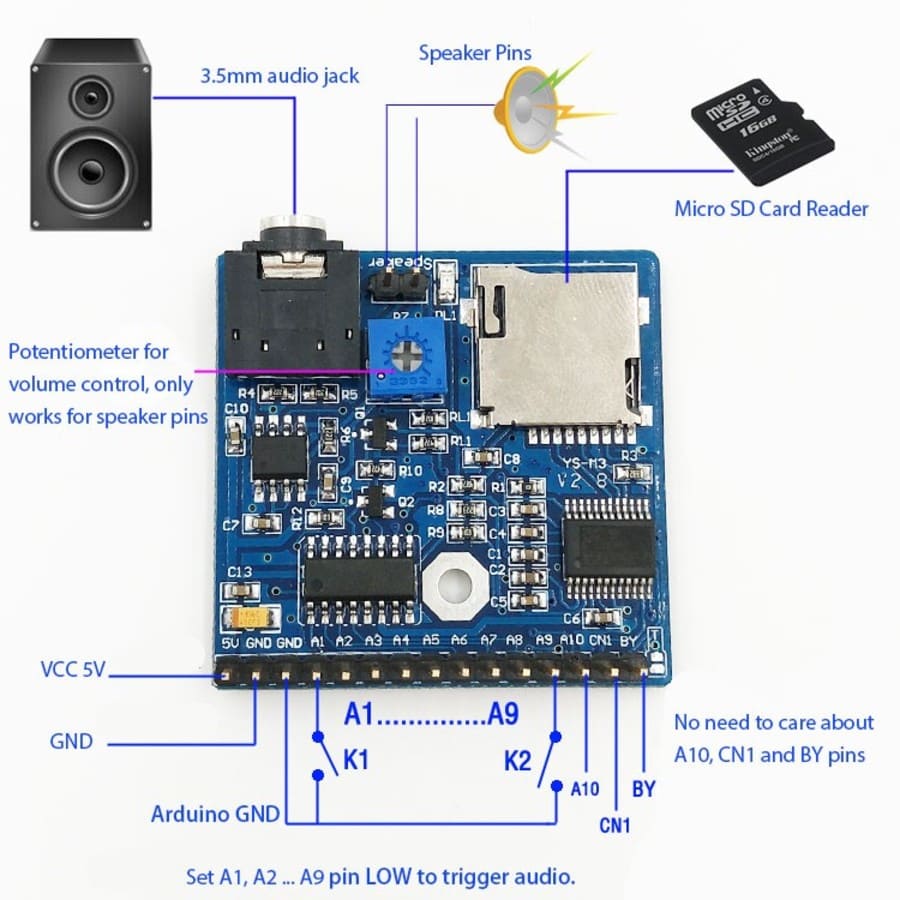
The third board is the MP3 player shield, which I needed for the recorded information feature, I bought it from a local online store, it had all the pinout information I needed to connect the shield to the microcontroller. So, I added a 15 pin headers to my schematic to easily insert the pins of the shield into my board.
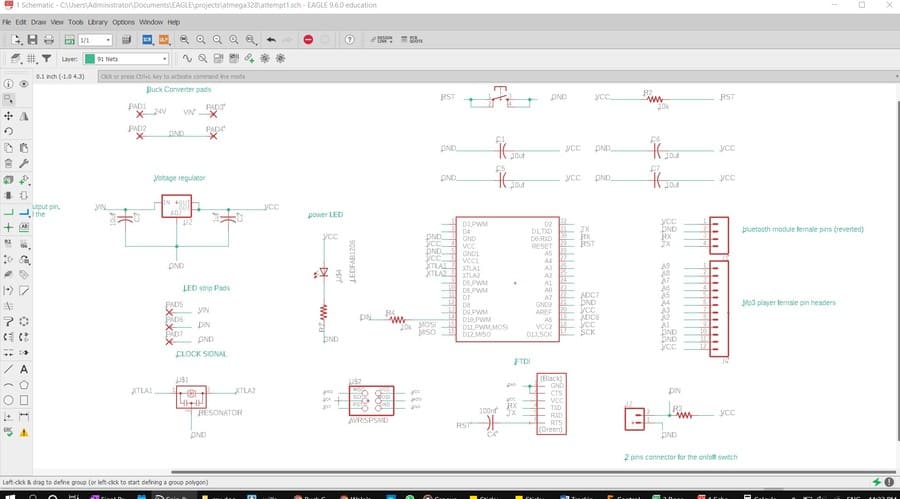
Full Schematic
After connecting all components, my schematic became ready to be converted to full board, image below shows the full schematic.
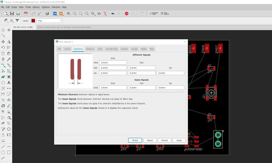
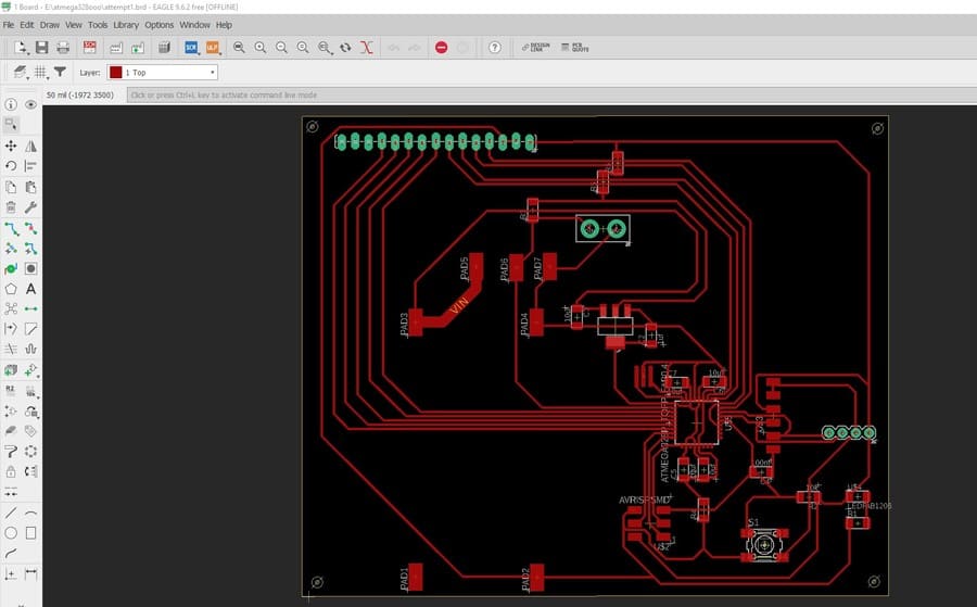
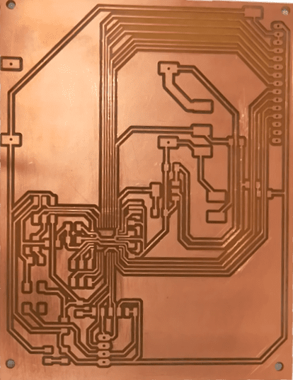
Traces
Now starting the fun part, drawing the traces between the components. It’s a puzzle like for me, though it’s very hard thing to do. using EAGLE, first i set the clearance and sizes to 0.4mm which equals the diameter of the mill bit, and then started drawing routes to connect the nodes.
after I spent two days trying to make it as much optimized as possible, I finally got a satisfying result for my first full PCB, officially.
Ouput Devices
I had two output devices in my project, light and voice systems.
RGB LED
TFor the light I used addressable RGB LED Strips. since I needed to light each area separately, I used this type of LEDs. The addressable LEDs uses only one pin from the microcontroller (pin 4 in my schematic), which is the DATA_IN pin which receives the data from the microcontroller and sends it to the following LEDs through a DATA_OUT pin in the second side, and so on.
When I fixed the LEDs in their places in the slots at the bottom layer, and started connecting them I made sure that the output tip from the first LED is connected to the input tip in the following led and so on. Also, the ground for all the LEDs connected together through a common ground line I fixed at the top of the back side of the panel. and I did the same for the VCC.
then numbered the LEDs in the board and divided the countries as matrices. Each set of LEDs represents a specific country area.
 /
/
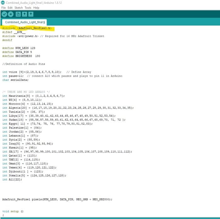
I used Adafruit_NeoPixel library to be able to control the array of LEDs. It has testing codes, I used them to check that all the LEDs are connected properly and working.
MP3 player
In order to play the recorded information about each country, I had to use an external mp3 player, it can play only 9 tracks, I saved them on a SD card and fixed the module to the pin header I added before.
Each pin header from A0 to A9 will play one of the track depending of its name in the SD card; A1 will play track named 01, A2 will play 02 , and so on as I explaind in the programming section. And the other pins were for the Microcontroller, VCC and GND.
For the speaker, I used the same TV speaker that I used in the output devices week, each one had only two pins, one for the VCC and one for the GND.
Electronics Production
Milling
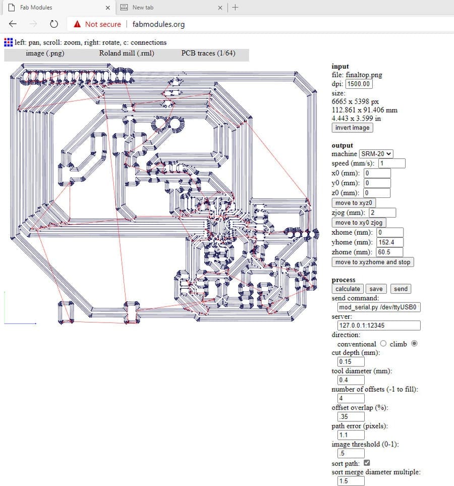
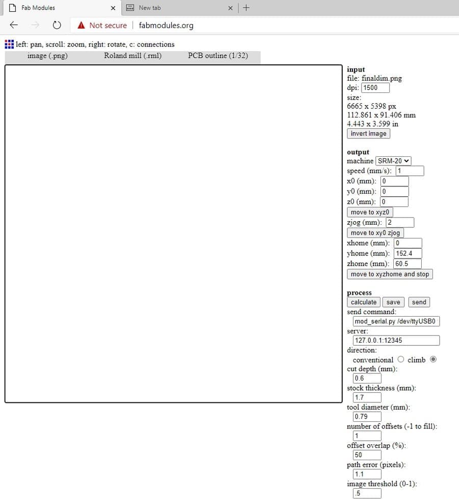
Then I exported the top layer from EAGLE as PNG image with resolution of 1500 ppi , I send it to the fab modules website and prepared it to be milled using the 1/32 flat end mill. And the image below shows the settings I used. and I repeated the same process with the dimensions layer to cut out the outline traces.
Slodering
After finishing the board looked like this, I started cleaning it and preparing it to the soldering stage, first I added solder to all the pads and traces to make the soldering easier, and then started adding the components one by one.
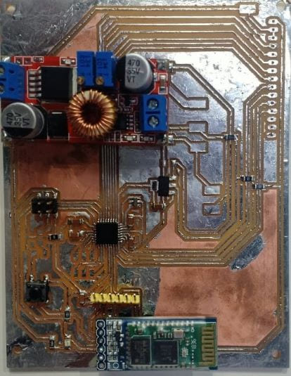
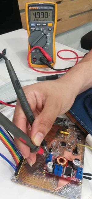
Unfortunately, when I tried to burn the boot loader to test the board, it worked once and stopped working after that. I tried to test the connectivity for each component using the multimeter to make sure that there is no Disconnected areas or short circuits between the components but nothing appeared to be causing the problem. So I had to unsolder the components and clean the board with alcohol and brush and then resoldered them, it worked, I think the problem was with soldering the FTDI pin headers because when I desoldered them I noticed a lot of solder and tiny particles between the legs of the pin headers.
Programming
Now, the fun part. How I will tell the board to do exactly what I need, how to make it interactive!
RGB LEDs Code
To know how to write the code, first I wrote a scenario of how the project will work. In the simple way, each time I press the country name it should light up and the recorded information about this country should start playing. But I needed a very detailed construction of what will happen when I press any button.
when I attached the LEDs in the slots at the back of the map, I numbered them to make the programming step easier. So, I made an excel sheet contains each country name, the number of LEDs for it, and number of the starting pin and ending pin for that country in order to create the arrays.
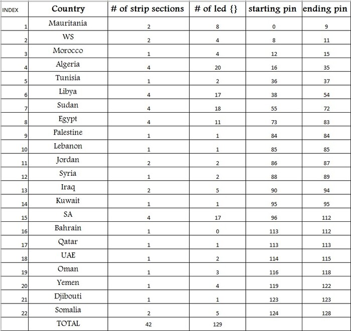
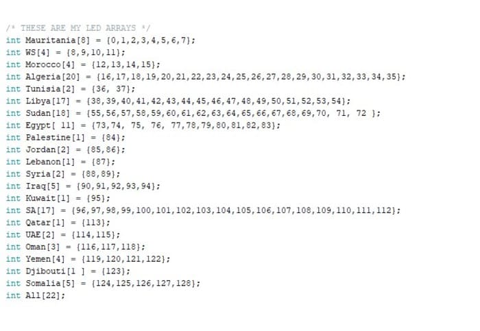
So, each country will have an array named on it. And each array in the Arduino code will contain the set of LEDs index under that country.
notice in defining the arrays, the number of elements inside each array defined in square brackets after its name, and the ALL array contains 22 elements which corresponds to all previous arrays.
Now, what we will do with all these arrays, we need to refer to them somewhere in the code, so that when a specific condition is met, this set of LEDs should light up (in random colors).
I used switch statement to do that, in each case we will light only one array (country). I defined a new variable (serial Data), and depending on the returned value from the serial monitor (I was testing the code using the FTDI) the correct case will work, which means the corresponding array will light.
The cases values should be char data which means only one letter or character, so the first country in the right (Mauritania [10]) which has the array elements from 0 to 9 I referenced to it as case 1, and the second country case2 and so on to case 9 (Palestine) and then started capital letters A for Jordan and B for Lebanon…etc.
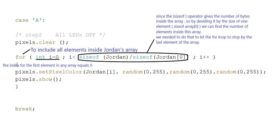
Included Adafruit_NeoPixel.h library, to control the LEDs. I used from it some simple functions, (pixels.setPixelColor) which takes 4 parameters one for the index of the led that we want to set its color , in my case I used the arrays that I created before, to be able to refer to more than one LED together. and the other 3 parameters to set the exact color code Red, Green, Blue respectively.
And the other functions I used were the pixels.show(); which turns all LEDs off, and pixels.show(); light up the LED.
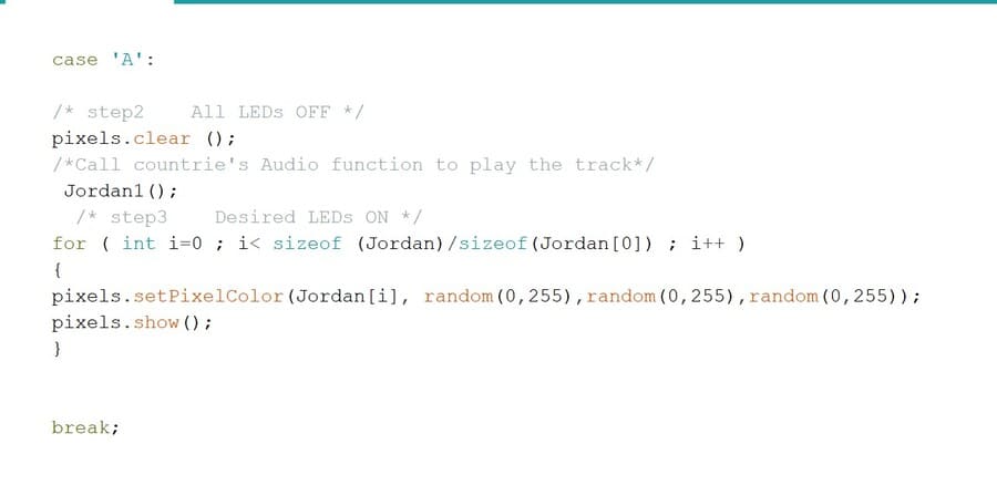
Let’s talk about Jordan’s button for example, since it’s a small country, it needed only two LEDs under it. From the excel sheet, the pins are 85 & 86. And depending on its order its charechter will be A , so each time I need to light it, I will call the A case; which in its turn will set its color to a random color and then show it( light it).
MP3 Player Code
After finishing the LEDs code, I had to program the mp3 player separately to make sure that each part is working, and then combine them in one code. referencing from the website where I purchased the module “By keeping LOW one of the module’s A1-A9 pins and the rest of the pins HIGH, the MP3 module will automatically play the LOW pin’s track. The A1 pin assigned to 001.mp2. A2 to 002.mp3… Just as simple as that! In this way, you can implement up to 9 tracks!”.
So, in order to do that I defined a new array includes the numbers of the module pins in the microcontroller ordered from A1 to A9, to be able to refer to them when we want to set them HIGH or LOW. And a new variable called pause (A10) in the module which connected to pin 11 in the microcontroller in my schematic.
Now we have to create audio functions for each track of the 9 tracks. So, when I call the function it returns the value of the pin associated with that track to be low then high so that track plays.
Again let’s take a look at Jordan’s function (named it jordan1 to make it easier to call it inside Jordan’s case), since it’s track name in the SD card was (08), its pin index is 8. and from the audio array, the eighth pin was 9, so each time I have to play Jordan’s track, I need to turn the pin 9 low then high.
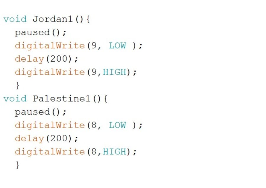
And then in Jordan’s case I called its function, to be like the image below.
And of course I did that for other 8 countries, I selected them randomly because I couldn’t play more than 9 tracks, hopefully in the future I will upgrade it and use mp3 player module with more tracks.
As I mentioned before, I used the FTDI to make the testing step easier, but after I finished writing it I switched to the Bluetooth communication as I will explain in the networking section.
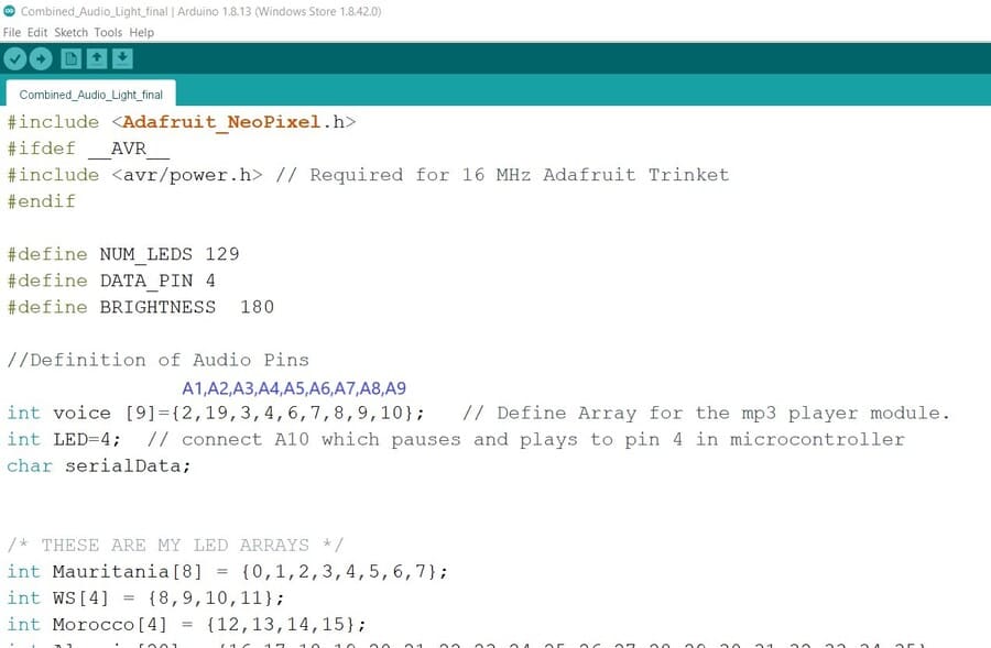
        #include
#ifdef __AVR__
#include  // Required for 16 MHz Adafruit Trinket
#endif

#define NUM_LEDS 129
#define DATA_PIN 5
#define BRIGHTNESS  180

//Definition of Audio Pins

int voice [9]={2,19,3,4,6,7,8,9,10};   // Define Array for the mp3 player module.
int pause=11;  // connect A10 which pauses and plays to pin 11 in microcontroller
char serialData;


/* THESE ARE MY LED ARRAYS */
int Mauritania[8] = {0,1,2,3,4,5,6,7};
int WS[4] = {8,9,10,11};
int Morocco[4] = {12,13,14,15};
int Algeria[20] = {16,17,18,19,20,21,22,23,24,25,26,27,28,29,30,31,32,33,34,35};
int Tunisia[2] = {36, 37};
int Libya[17] = {38,39,40,41,42,43,44,45,46,47,48,49,50,51,52,53,54};
int Sudan[18] = {55,56,57,58,59,60,61,62,63,64,65,66,67,68,69,70, 71, 72 };
int Egypt[ 11] = {73,74, 75, 76, 77,78,79,80,81,82,83};
int Palestine[1] = {84};
int Jordan[2] = {85,86};
int Lebanon[1] = {87};
int Syria[2] = {88,89};
int Iraq[5] = {90,91,92,93,94};
int Kuwait[1] = {95};
int SA[17] = {96,97,98,99,100,101,102,103,104,105,106,107,108,109,110,111,112};
/*int Bahrain[1] = {139};*/
int Qatar[1] = {113};
int UAE[2] = {114,115};
int Oman[3] = {116,117,118};
int Yemen[4] = {119,120,121,122};
int Djibouti[1 ] = {123};
int Somalia[5] = {124,125,126,127,128};
int All[22];


Adafruit_NeoPixel pixels(NUM_LEDS, DATA_PIN, NEO_GRB + NEO_KHZ800);


void setup ()
{

  pixels.begin();
  pixels.clear();
  pixels.show();

  //Setup of audio


for ( int i=0 ; i< 9; i++ ){}
  pinMode (voice [i], OUTPUT);
}
pinMode (LED, OUTPUT);


  Serial.begin (9600);
}

void loop ()
{

 if (Serial.available())
 {
      serialData = Serial.read();
      Serial.print (serialData);
  Initialization(); //for audio initialization //
/* cases starts here */

      switch (serialData)
 {

    case '1':
    /* step2    All LEDs OFF */
    pixels.clear ();
    /*Call countrie's Audio function to play the track*/
      /* step3    Desired LEDs ON */
    for ( int i=0 ; i< (sizeof (Mauritania)/sizeof(Mauritania[0])) ; i++ )
    {
    pixels.setPixelColor(Mauritania[i], random(0,255),random(0,255),random(0,255));
    pixels.show();

    }

    break;


    case '2':
   /* step2    All LEDs OFF */
    pixels.clear ();
    /*Call countrie's Audio function to play the track*/
      /* step3    Desired LEDs ON */
    for ( int i=0 ; i< sizeof (WS)/sizeof(WS[0]) ; i++ )
    {
    pixels.setPixelColor(WS[i], random(0,255),random(0,255),random(0,255));
    pixels.show();
    }
    /* step4    Desired Voices ON */
    digitalWrite (voice[10],LOW);

    break;


    case '3':
    /* step2    All LEDs OFF */
    pixels.clear ();
    /*Call countrie's Audio function to play the track*/
      /* step3    Desired LEDs ON */
    for ( int i=0 ; i< sizeof (Morocco)/sizeof(Morocco[0]) ; i++ )
    {
    pixels.setPixelColor(Morocco[i], random(0,255),random(0,255),random(0,255));
    pixels.show();
    }
    /* step4    Desired Voices ON */
    digitalWrite (voice[10],LOW);
    break;


    case '4':
   /* step2    All LEDs OFF */
    pixels.clear ();
    /*Call countrie's Audio function to play the track*/
     Algeria1();
      /* step3    Desired LEDs ON */
    for ( int i=0 ; i< sizeof (Algeria)/sizeof(Algeria[0]) ; i++ )
    {
    pixels.setPixelColor(Algeria[i],  random(0,255),random(0,255),random(0,255));
    pixels.show();
    }
    /* step4    Desired Voices ON */

    break;


    case '5':
   /* step2    All LEDs OFF */
    pixels.clear ();
    /*Call countrie's Audio function to play the track*/
     Tunisia1();
      /* step3    Desired LEDs ON */
    for ( int i=0 ; i< sizeof (Tunisia)/sizeof(Tunisia[0]) ; i++ )
    {
    pixels.setPixelColor(Tunisia[i],  random(0,255),random(0,255),random(0,255));
    pixels.show();
    }
    /* step4    Desired Voices ON */

    break;


    case '6':
    /* step2    All LEDs OFF */
    pixels.clear ();
    /*Call countrie's Audio function to play the track*/
      /* step3    Desired LEDs ON */
    for ( int i=0 ; i< sizeof (Libya)/sizeof(Libya[0]) ; i++ )
    {
    pixels.setPixelColor(Libya[i],  random(0,255),random(0,255),random(0,255));
    pixels.show();
    }
    /* step4    Desired Voices ON */
    digitalWrite (voice[10],LOW);
    break;


    case '7':
    /* step2    All LEDs OFF */
    pixels.clear ();
    /*Call countrie's Audio function to play the track*/

      /* step3    Desired LEDs ON */
    for ( int i=0 ; i< sizeof (Sudan)/sizeof(Sudan[0]) ; i++ )
    {
    pixels.setPixelColor(Sudan[i], random(0,255),random(0,255),random(0,255));
    pixels.show();
    }
    /* step4    Desired Voices ON */
    digitalWrite (voice[10],LOW);
    break;


    case '8':
    /* step2    All LEDs OFF */
    pixels.clear ();
    /*Call countrie's Audio function to play the track*/
     Egypt1();
      /* step3    Desired LEDs ON */
    for ( int i=0 ; i< sizeof (Egypt)/sizeof(Egypt[0]) ; i++ )
    {
    pixels.setPixelColor(Egypt[i],  random(0,255),random(0,255),random(0,255));
    pixels.show();
    }
    /* step4    Desired Voices ON */

    break;


    case '9':
    /* step2    All LEDs OFF */
    pixels.clear ();
    /*Call countrie's Audio function to play the track*/
     Palestine1();
      /* step3    Desired LEDs ON */
    for ( int i=0 ; i< sizeof (Palestine)/sizeof(Palestine[0]) ; i++ )
    {
    pixels.setPixelColor(Palestine[i], random(0,255),random(0,255),random(0,255));
    pixels.show();
    }
    /* step4    Desired Voices ON */

    break;


    case 'A':

    /* step2    All LEDs OFF */
    pixels.clear ();
    /*Call countrie's Audio function to play the track*/
     Jordan1();
      /* step3    Desired LEDs ON */
    for ( int i=0 ; i< sizeof (Jordan)/sizeof(Jordan[0]) ; i++ )
    {
    pixels.setPixelColor(Jordan[i], random(0,255),random(0,255),random(0,255));
    pixels.show();
    }


    break;


    case 'B':

    /* step2    All LEDs OFF */
    pixels.clear ();
    /*Call countrie's Audio function to play the track*/

      /* step3    Desired LEDs ON */
    for ( int i=0 ; i< sizeof (Lebanon)/sizeof(Lebanon[0]) ; i++ )
    {
    pixels.setPixelColor(Lebanon[i], random(0,255),random(0,255),random(0,255));
    pixels.show();
    }
    /* step4    Desired Voices ON */
    digitalWrite (voice[10],LOW);
    break;


    case 'C':
    /* step2    All LEDs OFF */
    pixels.clear ();
    /*Call countrie's Audio function to play the track*/
      /* step3    Desired LEDs ON */
    for ( int i=0 ; i< sizeof (Syria)/sizeof(Syria[0]) ; i++ )
    {
    pixels.setPixelColor(Syria[i], random(0,255),random(0,255),random(0,255));
    pixels.show();
    }
    /* step4    Desired Voices ON */
    digitalWrite (voice[10],LOW);
    break;


    case 'D':
    /* step2    All LEDs OFF */
    pixels.clear ();
    /*Call countrie's Audio function to play the track*/
      /* step3    Desired LEDs ON */
    for ( int i=0 ; i< sizeof (Iraq)/sizeof(Iraq[0]) ; i++ )
    {
    pixels.setPixelColor(Iraq[i],  random(0,255),random(0,255),random(0,255));
    pixels.show();
    }
    /* step4    Desired Voices ON */
    digitalWrite (voice[5],LOW);
    break;


    case 'E':
    /* step2    All LEDs OFF */
    pixels.clear ();
    /*Call countrie's Audio function to play the track*/

      /* step3    Desired LEDs ON */
    for ( int i=0 ; i< sizeof (Kuwait)/sizeof(Kuwait[0]) ; i++ )
    {
    pixels.setPixelColor(Kuwait[i],  random(0,255),random(0,255),random(0,255));
    pixels.show();
    }
    /* step4    Desired Voices ON */
    digitalWrite (voice[10],LOW);
    break;


    case 'F':
   /* step2    All LEDs OFF */
    pixels.clear ();
    /*Call countrie's Audio function to play the track*/
     SA1();
      /* step3    Desired LEDs ON */
    for ( int i=0 ; i< sizeof (SA)/sizeof(SA[0]) ; i++ )
    {
    pixels.setPixelColor(SA[i],  random(0,255),random(0,255),random(0,255));
    pixels.show();
    }
    /* step4    Desired Voices ON */

    break;


/*
    case 'G':
    for ( int i=0 ; i< sizeof (Bahrain)/sizeof(Bahrain[0]) ; i++ )
    {
    pixels.setPixelColor(Bahrain[i], 0,0,255);
    pixels.show();
    }
    break;
*/


    case 'H':
   /* step2    All LEDs OFF */
    pixels.clear ();
    /*Call countrie's Audio function to play the track*/

      /* step3    Desired LEDs ON */
    for ( int i=0 ; i< sizeof (Qatar)/sizeof(Qatar[0]) ; i++ )
    {
    pixels.setPixelColor(Qatar[i], random(0,255),random(0,255),random(0,255));
    pixels.show();
    }
    /* step4    Desired Voices ON */
    digitalWrite (voice[10],LOW);
    break;


    case 'I':
    /* step2    All LEDs OFF */
    pixels.clear ();
    /*Call countrie's Audio function to play the track*/
     UAE1();
      /* step3    Desired LEDs ON */
    for ( int i=0 ; i< sizeof (UAE)/sizeof(UAE[0]) ; i++ )
    {
    pixels.setPixelColor(UAE[i],  random(0,255),random(0,255),random(0,255));
    pixels.show();
    }
    /* step4    Desired Voices ON */

    break;


    case 'J':
    /* step2    All LEDs OFF */
    pixels.clear ();
    /*Call countrie's Audio function to play the track*/

      /* step3    Desired LEDs ON */
    for ( int i=0 ; i< sizeof (Oman)/sizeof(Oman[0]) ; i++ )
    {
    pixels.setPixelColor(Oman[i],  random(0,255),random(0,255),random(0,255));
    pixels.show();
    }
    /* step4    Desired Voices ON */
    digitalWrite (voice[10],LOW);
    break;


    case 'K':
    /* step2    All LEDs OFF */
    pixels.clear ();
    /*Call countrie's Audio function to play the track*/
     Yemen1();

      /* step3    Desired LEDs ON */
    for ( int i=0 ; i< sizeof (Yemen)/sizeof(Yemen[0]) ; i++ )
    {
    pixels.setPixelColor(Yemen[i], random(0,255),random(0,255),random(0,255));
    pixels.show();
    }
    /* step4    Desired Voices ON */

    break;


    case 'L':
    /* step2    All LEDs OFF */
    pixels.clear ();
    /*Call countrie's Audio function to play the track*/

      /* step3    Desired LEDs ON */
    for ( int i=0 ; i< sizeof (Djibouti)/sizeof(Djibouti[0]) ; i++ )
    {
    pixels.setPixelColor(Djibouti[i],  random(0,255),random(0,255),random(0,255));
    pixels.show();
    }
    /* step4    Desired Voices ON */
    digitalWrite (voice[10],LOW);
    break;


    case 'M':
    /* step2    All LEDs OFF */
    pixels.clear ();
    /*Call countrie's Audio function to play the track*/

      /* step3    Desired LEDs ON */
    for ( int i=0 ; i< sizeof (Somalia)/sizeof(Somalia[0]) ; i++ )
    {
    pixels.setPixelColor(Somalia[i], random(0,255),random(0,255),random(0,255));
    pixels.show();
    }
    /* step4    Desired Voices ON */
    digitalWrite (voice[8],LOW);
    break;


    case 'N':
    All1();
    for ( int i=0 ; i < NUM_LEDS ; i++ )
    {
    pixels.setPixelColor(i, random(0,255),random(0,255),random(0,255));
    pixels.show();
    }
    break;

}
}
}

void Jordan1(){
  paused();
  digitalWrite(9, LOW );
  delay(200);
  digitalWrite(9,HIGH);
  }
void Palestine1(){
  paused();
  digitalWrite(8, LOW );
  delay(200);
  digitalWrite(8,HIGH);
  }


void SA1(){
  paused();
  digitalWrite(4, LOW );
  delay(200);
  digitalWrite(4,HIGH);
  }


void UAE1(){
  paused();
  digitalWrite(3, LOW );
  delay(200);
  digitalWrite(3,HIGH);
  }


void Algeria1(){
  paused();
  digitalWrite(7, LOW );
  delay(200);
  digitalWrite(7,HIGH);
  }


void Tunisia1(){
  paused();
  digitalWrite(19, LOW );
  delay(200);
  digitalWrite(19,HIGH);
  }


void Yemen1(){
  paused();
  digitalWrite(2, LOW );
  delay(200);
  digitalWrite(2,HIGH);
  }


void All1(){
  paused();
  digitalWrite(10, LOW );
  delay(200);
  digitalWrite(10,HIGH);
  }

void Egypt1(){
  paused();
  digitalWrite(6, LOW );
  delay(200);
  digitalWrite(6,HIGH);

}


void Initialization(){
  for(int i=0; i<9;i++){
  digitalWrite(voice[i], LOW );
  delay(50);
  digitalWrite(voice[i],HIGH);
  }
  paused();
}

void paused(){
   digitalWrite(pause, LOW);
    delay(200);
  digitalWrite(pause, HIGH);
}
}
}
Interface and Application Programming
During the Application and Interface Programming week, I learned how to use python to create a desktop application, but now I decided to create a mobile application for my final project, for the ease of use.
After a lot of search about the best way to create the mobile application, I used the MIT App Inventor, it’s an online website helps you to customize your mobile application and then download it to your phone to test it.
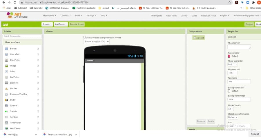
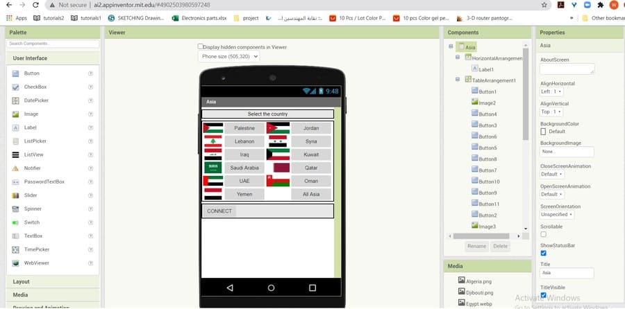
I created an account for the site, and started creating my first application. It’s really an easy way to make an app. you have two tabs, one the Designer tab which helps you to drag the components that you need in your app and visualize them in the way you need. The components might be any button or image or icon or list. And the inventor gives you the choice to create more than one page, which I made for the Continents. And the designer tab helps you create connections between the buttons and components you created in the blocks tab. the blocks might be logical or control blocks or math…etc. depending on the connection condition you need.
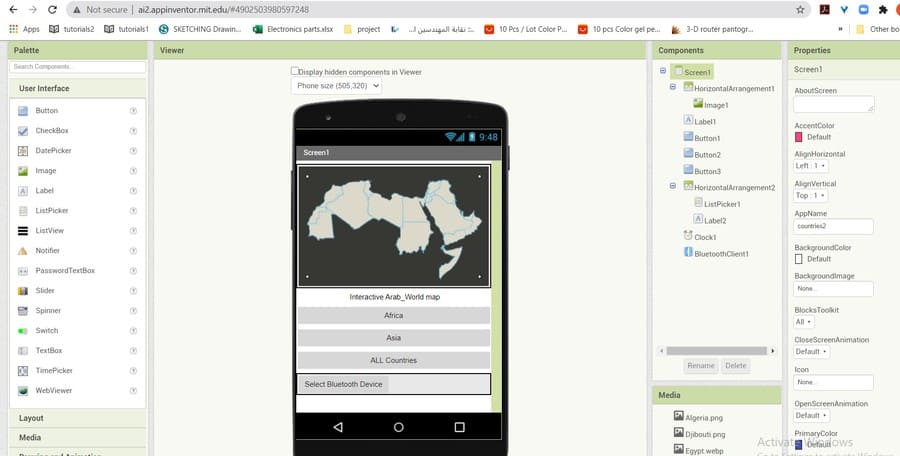
So, I created three screens(pages), and created buttons for each country in the screens. The first screen which is the home screen I had 3 buttons, one to open the Africa screen, and the second to open the Asia screen and the third to light up all the countries together (which referenced in the code as N char). And I added a photo for the map in this screen.
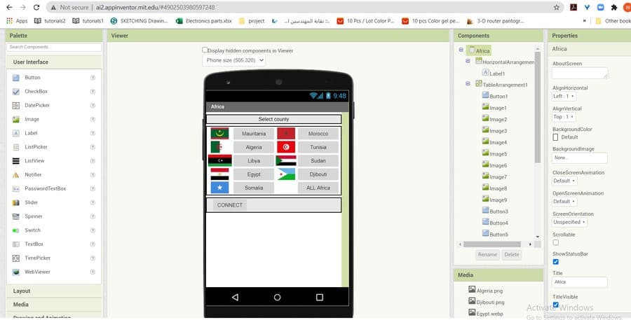
In the second and third screens I did the same, added buttons for each country and image for its flag, and listed them like in image below.
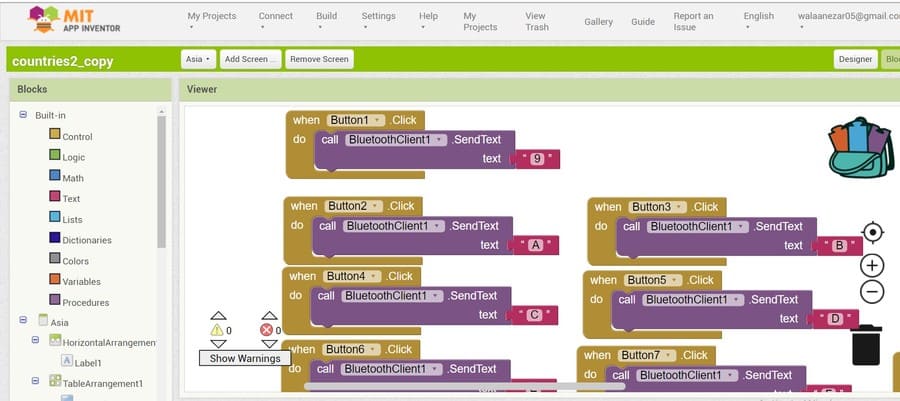
and Then in the blocks tab I started dragging the blocks depending on the function of the buttons or icons. For example, as explained in the programming section I want the app sends “A” when I press Jordan’s button in the app. So, I added a (when) control block for the Jordan button (number two in the Asia screen) tells the application to send “A” each time this button clicked. And so on for all other buttons.
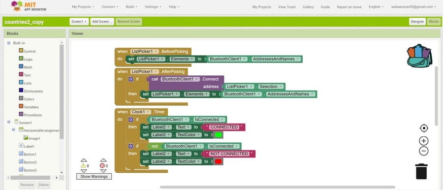
The last and most important step in creating the app was the Bluetooth connectivity function in the app. I needed my app to be able to select a Bluetooth device and send the commands through it. So, I added a list picker, real time clock and Bluetooth client components in the designer tab, and then in the blocks tab I added blocks as in the image below.
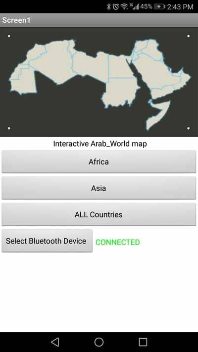
And below an images for the app working in in my mobile.
Networking and Communications
I used in my final project both serial communication and wireless Bluetooth signal.
I used the serial communication FTDI in my final project at the begging when I was testing the code. from the serial monitor in the Arduino IDE, I write the letter or number then the board and the LEDs responds depending on that number case in the code. It was very fast way, helped me debug the code easily without having to remove the Bluetooth device each time I upload a code, and reconnect to the mobile phone.
But as a major communication device, I used the Bluetooth, since I don’t need to control the project from large distances, each time you will use the mobile application you will be in front of the project.
I added four pin headers for the Bluetooth signal as I mentioned in the design section, the TX pin form the Arduino connected to the RX in the Bluetooth, and vice versa. The other two pins were the VCC and the ground pin.
After completing the code, now the time to test the Bluetooth connection. I uploaded the code to the board using my ISP programmer (while the Bluetooth is disconnected), then I connected it and sent commands to it using a mobile application called serial Bluetooth terminal. It’s a simple app allows you to connect to your Bluetooth device (after finding it and pairing it the the phone), and send commands depending on your code.
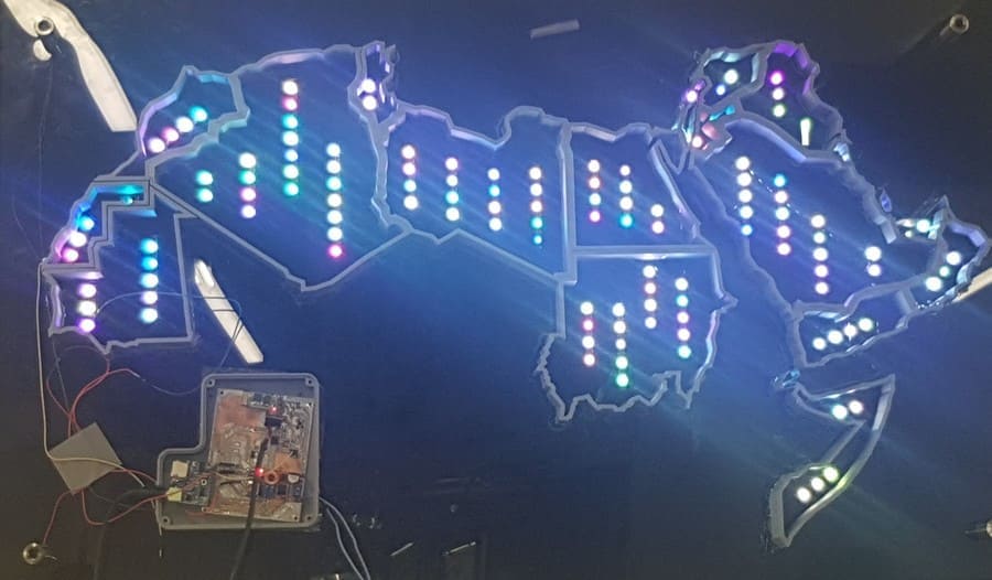
now the moment of truth, I had to test the map from the mobile application that I created before. the below video shoes the map working.
we hanged the map to the wall by the mounting screws, and connected it to
you can find all requerd files and codes in the files section below.
Bill Of Materials
Below table shows all materials I've used in my final project.
| Component / Material | Source | Cost |
|---|---|---|
| ATmega microcontroller | LAB | 2JOD |
| mp3 player sheild | MicroElectrone (Online Store) | 16JOD |
| Addressable RGB LED Strips | (Online Store) | 10 JOD/Meter |
| Resistors | LAB | 3JOD |
| FTDI | LAB | 2JOD |
| 40_Watt power supply | available in the LAB | 15JOD |
| pin Headers and Wires | LAB | 1JOD |
| Capacitors and Regulator | LAB | 3JOD |
| black and white 3_mm acrylic | LAB | 45JOD |
| Mounting screws | Local Stores | 5 JOD |
| adhesive | LAB | 2JOD |
| Total | --- | 120JOD///160$ |
All my Designs and Files
I created a repository in google drive for All the final project files
I also uploaded 4 Cura files for the 3D printed Boarders, and the Ready to print G-Code files.