Output Devices
The individual assignment for this week was to add an output device to our board and program it to do something, but since I can’t get to the lab and all my boards are back there, I couldn’t do this assignment. But I did made circuits in tinker cad and programmed them with Arduino and assembled them with the hardware tools kit.
First Circuit
From the beginning I wanted to play with the LCD, I don’t know why but I think it’s cool and I can make some nice stuff with it, but after finishing the circuit and the cod in tinkercad, I started assembling but I had a problem with attaching the LCD with the breadboard, since it needs soldering to fix it with the pin headers and I don’t have soldering tool in my home.
In the image below you can see the circuit and the code of the circuit. and the video shows the simulation of it using tinkercad.

Second Circuit
For The second circuit I used an audio speaker I took from old broken TV, I wanted to test it since I tend to use it in my final project as the audio system. to control the speaker, I added a simple switch. it’s a simple circuit and the connection is very easy, shown in image below.
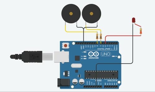
The components I used in the circuit are listed in the figure below, which is a screenshot from the website also.

For the code,i learned a new functions, notone and tone, which used to select the tones that will be heard from the speakers and there frequancy and durations. and I had to define some variables that will be used in the code, it’s a simple code also and I faced no problems writing it, you can see it below.
int switchstat;
int pos = 0;

void setup()
{
  pinMode(2, INPUT);
  pinMode(8, OUTPUT);
  pinMode(5, OUTPUT);
  pinMode(7, OUTPUT);
}

void loop()
{ switchstat = digitalRead(2);
  if (switchstat == LOW ) {
  noTone(8);
  digitalWrite (5, HIGH);
  delay(200);
  digitalWrite (5, LOW);
  delay(200);
  tone(7, 988, 300); // play tone 71 (B5 = 988 Hz)
  delay(200); // Wait for 500 millisecond(s)
  noTone(7);
  tone(8, 1047, 300); // play tone 72 (C6 = 1047 Hz)
  delay(200); // Wait for 300 millisecond(s)
}}
Then, started assembling the components in the breadboard with the Arduino, and copied the code to the Arduino IDE and uploaded it to the Arduino.


and the video below shows the test, turn the audio on to listen to the tones.
Download the code
Final project Outout Devices
For the final project, I used 2 types of output. You can find all the details in the Final Project Tracking page.
Touch Sensor
The last assignment I did was a DC motor direction changing by a touch sensor.
All the details of how I designed the board and produced it in the input devices page. But here I will talk about the DC motor I used and its pinout
I used a small DC with its own gearbox, its in the lab stock from old time and we don’t have a datasheet or anything for it. So, I connected it to the power supply to see if its working and it was very good and powerful.

The first decision I had to take is if I need the motor to run only in one direction or in two (forwards or backwards). Because If I wanted it in one direction I have to use a mosfet circuit, and for two direction I will use H-bridge circuit.
I decided to make in two directions since I was planning to design a small walking robot for it in the future. So , I started reading about H-bridge principle, connections, and pinout.

Connected it in eagle to the microcontroller as seen below, where pins DC1, DC2 where the input pins to the H-bridge from the attiny44, and the pins OUT1,OUT2 where the out pins connected directly to the motor terminals.

After finishing the soldering I connected the motor terminals to their pins, and added a large 3D printed flower to its shaft to help me recognize the direction of rotation.
Here is the final video.
see all the detailes in the Input Devices page.
DOWNLOAD THE CODE