Coputer ontrolled Cutting
For this week assignment, we learned how to use a 2d cad like the laser cutter and the vinyl cutter. For the group assignment we had to test our laser cutter performance, so me and my group (Ibrahim, Ahmad, Mohammed), each of us used a material to test it and compare our results.
Gruop Work
vinyl cutter
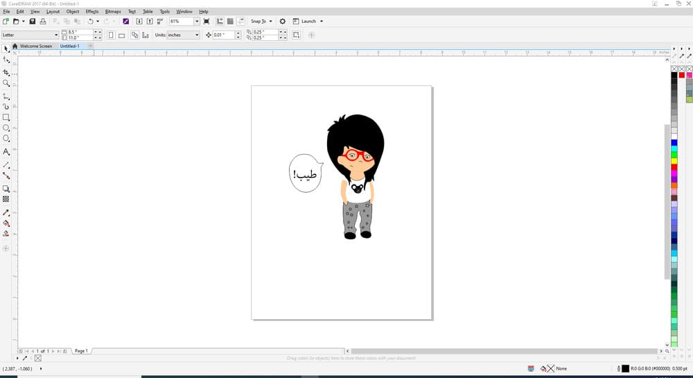
Individual assignment, first, I used the vinyl cutter to print and cut the vector drawing I drew last week using illustrator, I saved it as pdf and opened it from CorelDraw, see fig1.1.
in CorelDraw I selected the girl alone without the text and choose (create boundary), this created an outline to cut the photo over it, see fig1.2.
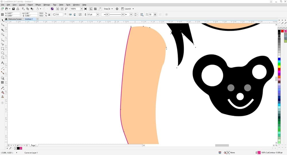
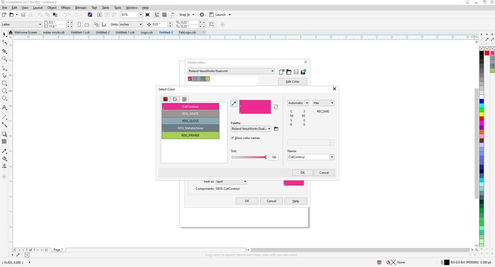
I selected this outline and changed the stroke color to (hex #ec2a90) by right clicking on its shortcut from the menu, see fig 1.3.
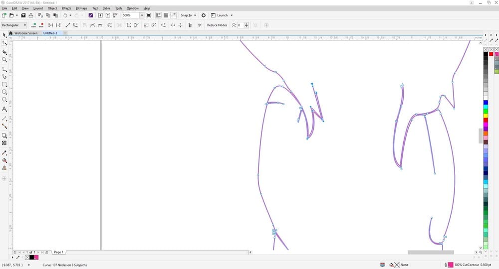
When I drew it in illustrator, I used the pin tool, and I was drawing each part as a closed area to be colored with its fill, so when I tried to cut it, the outline created more than area, which will cause cutting the poor girl to many parts. To solve this problem, I had to edit the outline trace I generated in CorelDraw by erasing all inner lines, see fig 1.4. And then I selected the text and made its outline to be cut. The last step in CorelDraw is to export the drawing to any directory, as a pdf file.
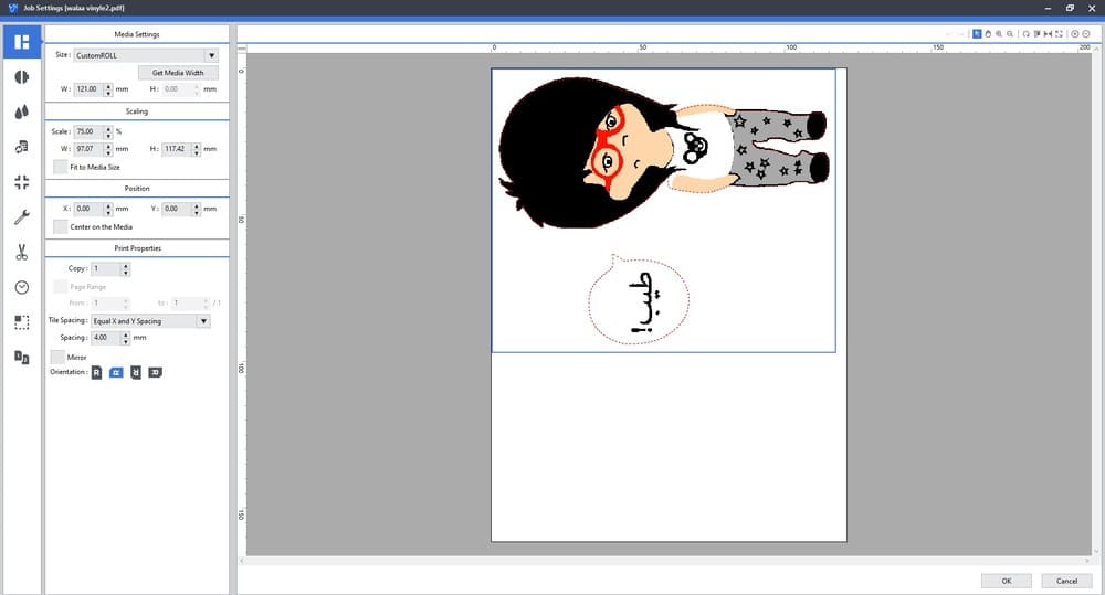
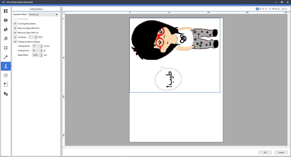
Now from the vinyl cutter software, versa works, I opened my file in queue A, and to open its setting just double click on it. From the dialogue box that appears, I cropped the photo to be around the drawing only, and I selected the role size which was 122mm, and for the cutting, I tried more than one scenario to have the perfect cut for the outline. In the first time I let the cutting force 60 with one pass which was not enough at all, see fig 1.5 & fig 1.6.
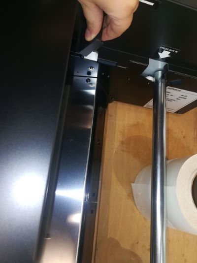
but before changing the settings again I decided to change the paper type, because the one I used was very shiny and glossy, and the ink didn’t stick to it properly. I used matte paper roll. To do that I lift up the arm and dragged the roll from the back, and inserted the new roll, see fig 1.7 & fig 1.8.
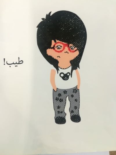
The new print turned out great, but it didn't cut at all. So I repeated it but with two passes, the cut was not through all. In the last trail I increased the cut force to 65 and made them 3 passes, so it was perfect as you can see. Fig 1.8.

and here is the pdf file
Laser Cutter
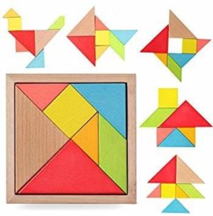
For the laser cutter, I had a problem because I wanted to do something special, but due to time constrains and the wide range of designs for the laser cut it was a little bit challenging. So I decided to design the construction kit first and then dedicate some time for the design. For the kit first I decided to cut polygons with joint cuts and generate 3d shapes form them as in the pic, but my instructor, Nadine told us that the kit should be constructed in different ways to form different structures. So, I decided to use the tangram puzzle, which is an old Chinese puzzle, it’s one of the most popular dissection puzzle in the world. It consists of seven flat parts (tans) generated from dividing a large square in a certain manner, these parts can form many different shapes, see fig 2.1.
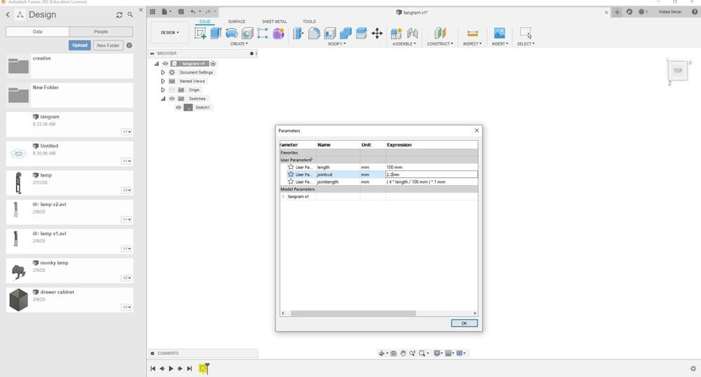
The first thing I did is drawing the tans, I drew them in fusion and added to each of them a joint cut to connect them together, I added one joint cut in the middle of each short line, and two or three cuts in the long edges. The design was paramedic, which means if I changed the material thickness or the size of the parts, all what I have to do is changing the parameter expression in the parameters set. See fig 2.2 & 2.3. all the parameters I used for this design.
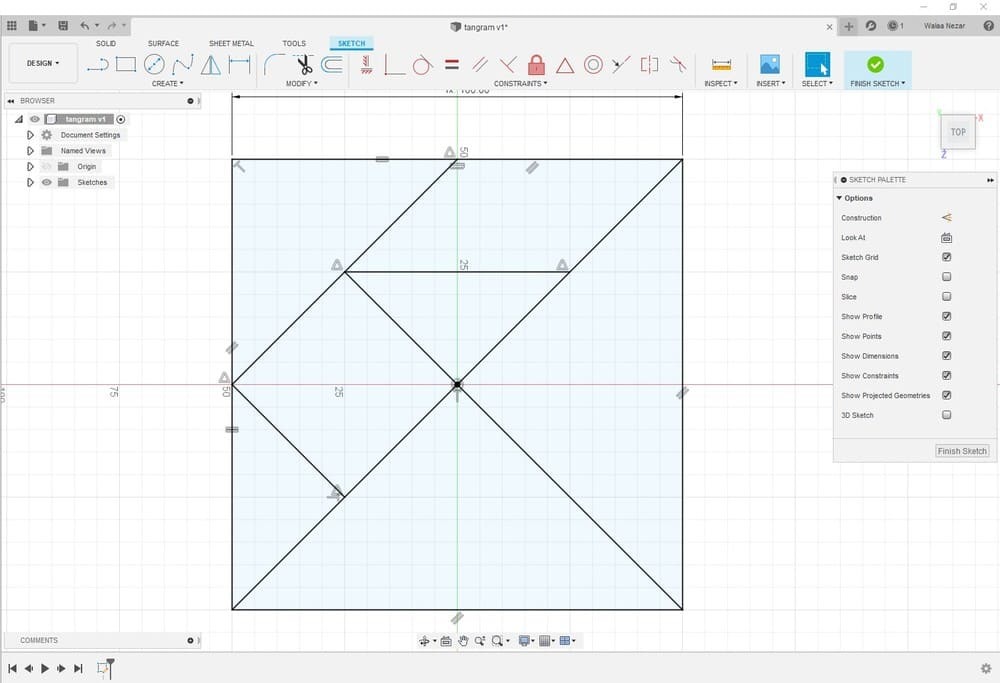
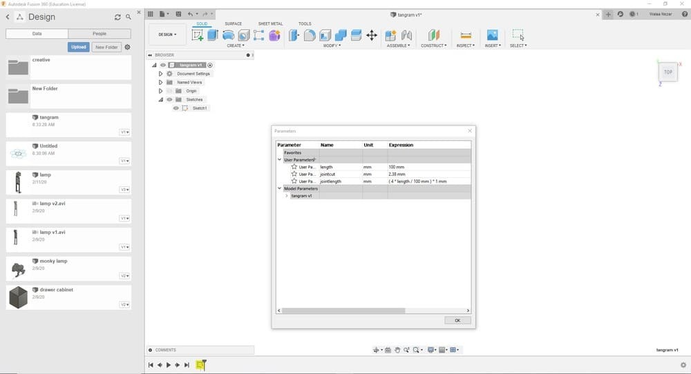
For the material thickness parameter, I took the kerf value that we had in the group assignment .12 mm and subtract it from the cut lengths to have a tight fit.
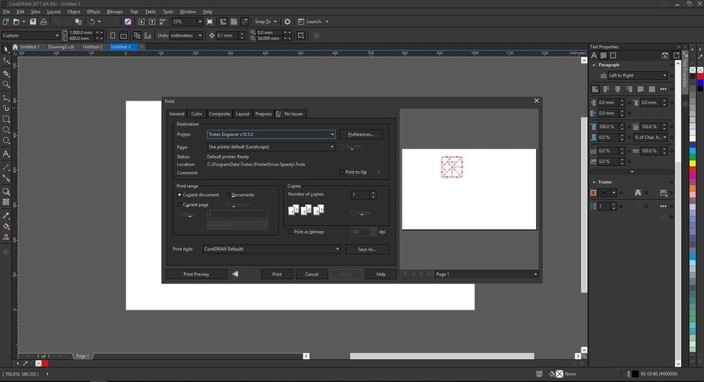
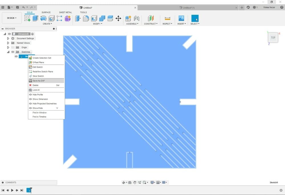
Then I saved the sketches as DXF and send them to CorelDraw, since my design was ready I just used the CorelDraw to make the lines red for the cut and gave it a print order to send it to the job control software for the speedy trotic laser cutter see fig 2.4.
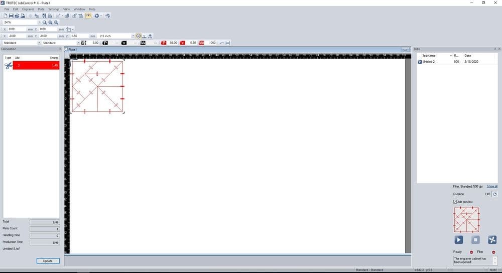
In the job control I dragged the file to the work space, and from the group work I choose the setting for acrylic 2.5 mm , which appears in fig 2.5.
In the firs cut I just cut two parts to assure the tight fit, and gave it the order by clicking ready button, it did cut through the acrylic but the fit was lose, so I went back to my design in fusion and changed the material thickness parameter to smaller value, I tried 0.1 offset, 0.2 decrease in the cut length instead of the 0.12 I used before ( cut length = 2.3mm), see fig 2.6. and I went back to the CorelDraw and the job control and tried it with the same settings. The cut was better but I wanted it to be more tight so I changed the parameter value in fusion again, and made it a 0.15 offset, 0.3 decrease in the parameter value (cut length = 2.2mm). by this time the fit was very good and I was pleased with the result.
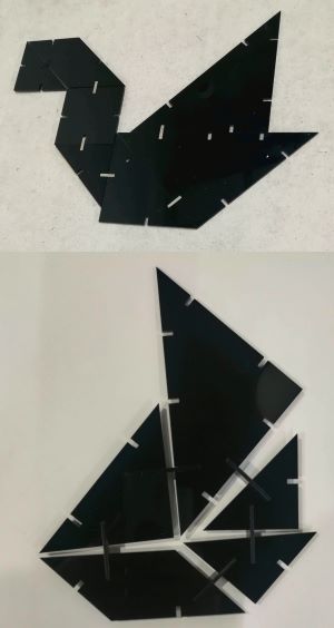
But for the assembly, it was just 2d assembly process and it hard to stand over or to be hanged and the joints didint gave the needed support, see fig 2.7. So, I decided to start a new kit and this time it had to be great.
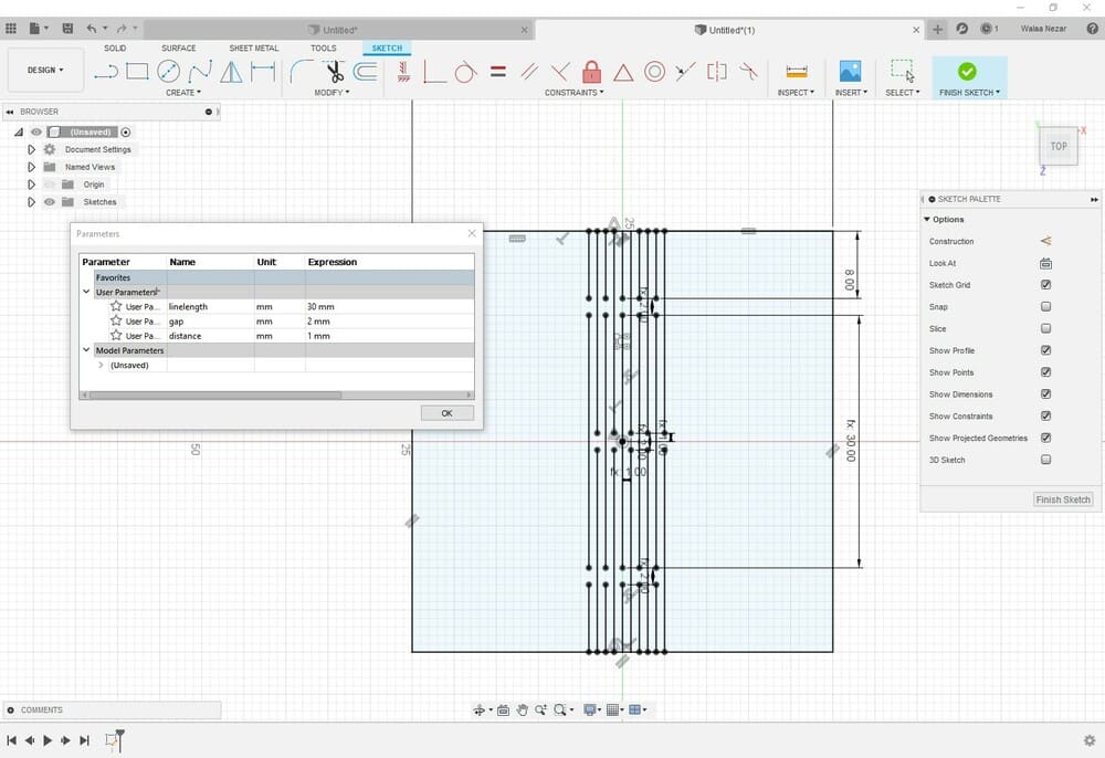
I started from scratch, I drew a living hinge, and tested it in a square piece of wood, after 3 attempt I got the results I wanted, each time I was changing the separation distance between the lines, see fig 3.1 & fig 3.2.
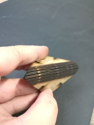
After finishing the piece, I was training it over to test the flexibility, then I had this idea, why I don’t just revolve the pattern to be parallel to the diagonal of the square, I did it and added joint cuts around its edges, see fig 3.3.
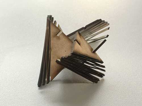
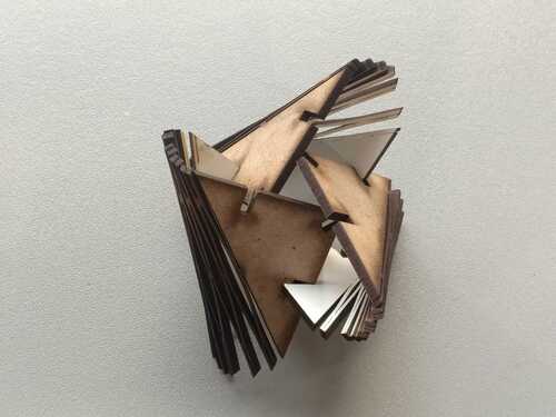
From the first time I was very happy with the results, I started connecting the pieces together to form different shapes, see below images.
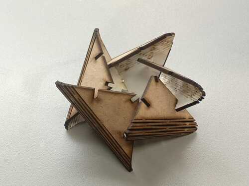
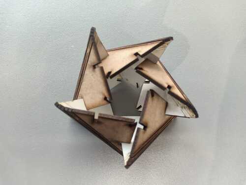
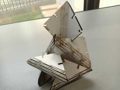
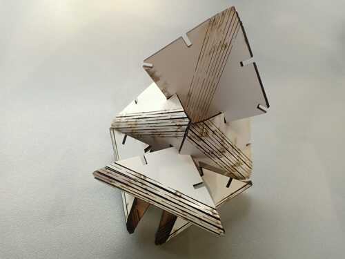
flexible kit
DXF flexible kit