Interface and application programming.
-
Group assignment
- Compare as many tool options as possible.
-
Individual assignment
Group assignment.
Individual assignment .
So for this assignment, I was going to make a game controller but I failed miserably so I changed the assignment to something easer but anyway I will explain what I did in the game controller and what I failed at and what I did make instead.
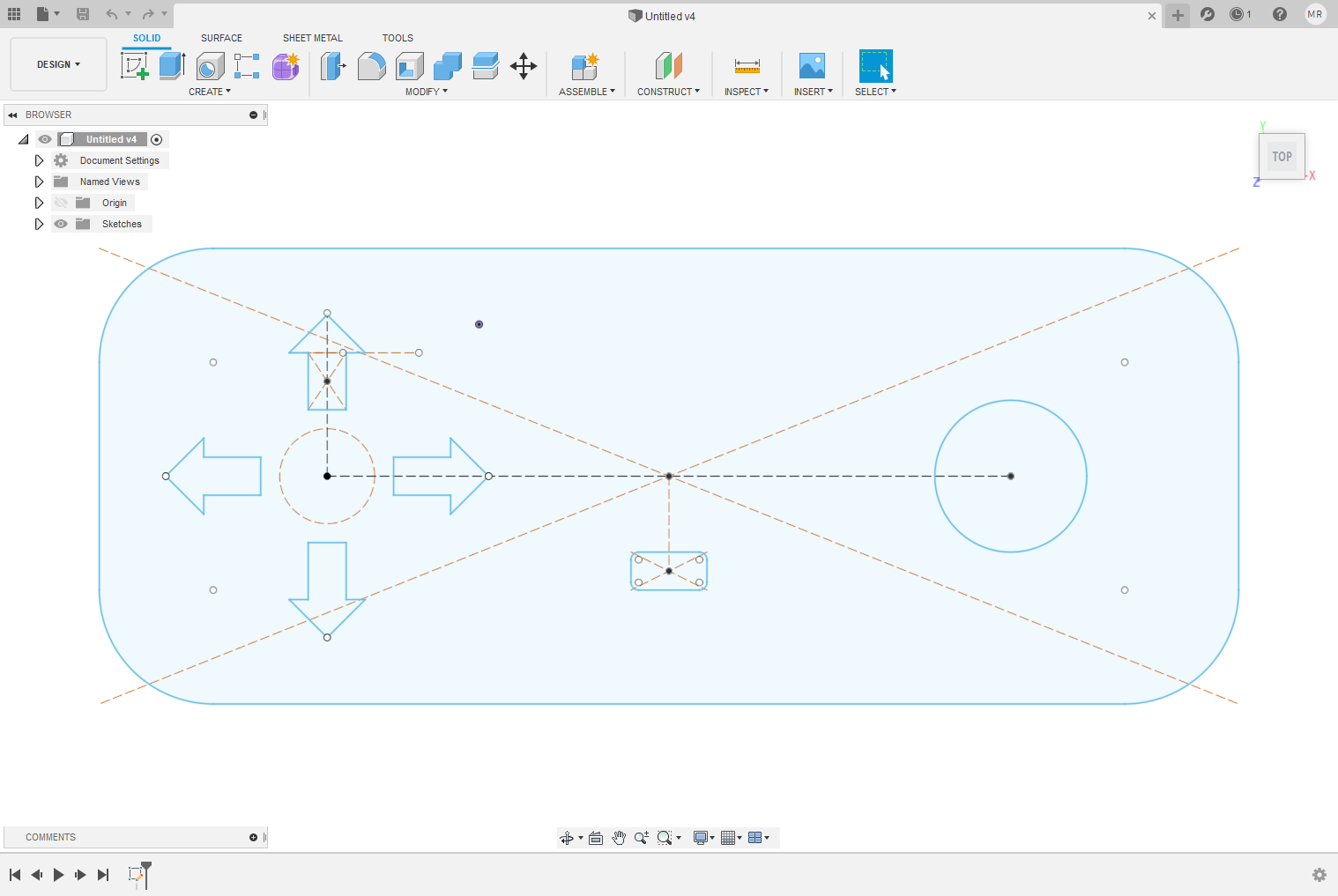
I start by drawing the outline for the game controller in fusion 360.
next for the Schematic so my pcb was inspired by Mohamed Kamel Input Devices
Now for the layout, I imported the DXF as a "Dimension" next is to add all the components

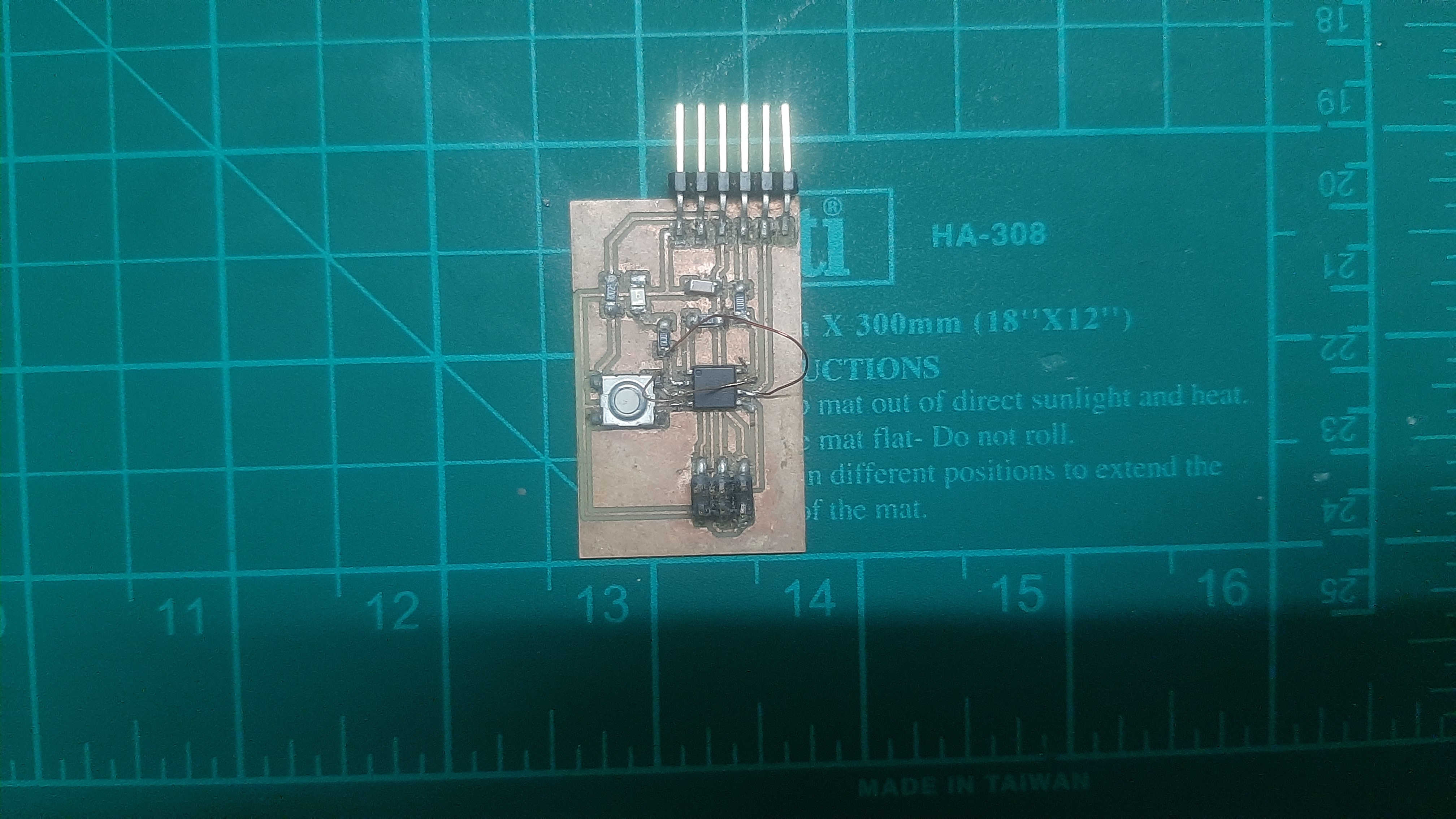
now after cutting the pcb and soldering the components for the programming phase so I modified Mohamed Kamel code and started to upload, I did make multiple problems one of them is configuring the fuse, but after solving all the problems but one problem I couldn't figure out when I hook up the pcb with the FTDI It was dumping a lot of noise data.
so I checked the pcb for a Short circuit but nothing but after a lot of testing and trails I have been advised to change the concept to something more easer
so I hade this idea to use electronic design pushbutton pcb in the interface assignment, so now I decided to use Processing to interface with the computer, next is how to use processing so I didn't know match about this program so I started with this video it had a lot of information about the new update and what change
now I understand more of how the program is working so it's time to write the code for my pcb, so as I understand the communication method that I will use is serial communication.
I started with Include the SoftwareSerial library and define the RX and TX pins.
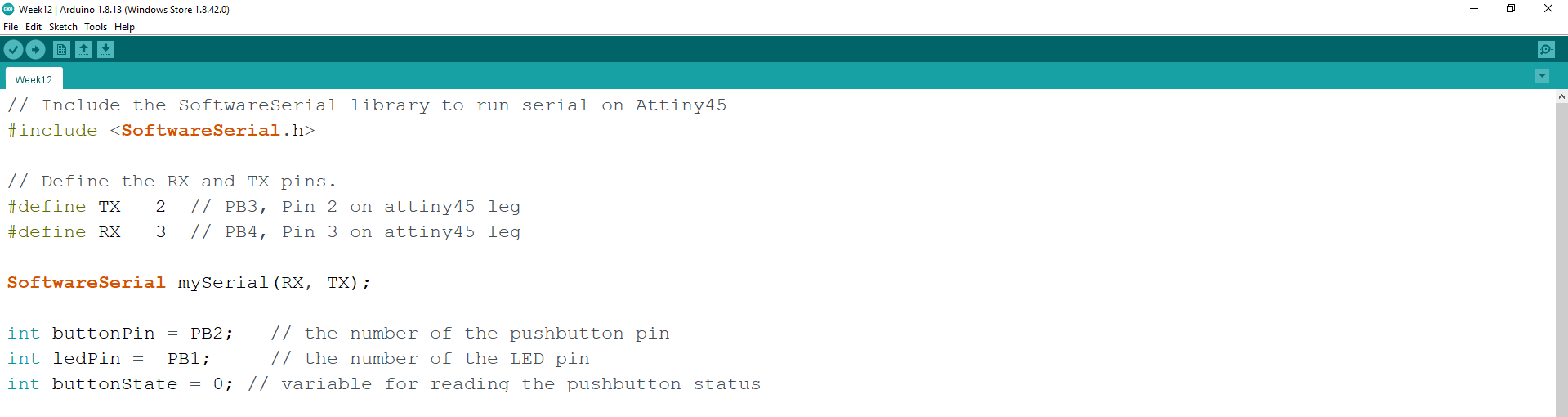
Next is to set the baud rates, so the baud rate is how fast data is sent over a serial line. It's usually expressed in units of bits-per-second (bps). If you invert the baud rate, you can find out just how long it takes to transmit a single bit. This value determines how long the transmitter holds a serial line high/low or at what period the receiving device samples its line.
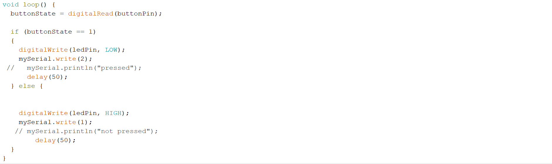
For the main code so I wright a simple code to just detect the button state and send digit through the serial port.
Arduino code.
// Include the SoftwareSerial library to run serial on Attiny45
#include < SoftwareSerial.h>
// Define the RX and TX pins.
#define TX 2 // PB3, Pin 2 on attiny45 leg
#define RX 3 // PB4, Pin 3 on attiny45 leg
SoftwareSerial mySerial(RX, TX);
int buttonPin = PB2; // the number of the pushbutton pin
int ledPin = PB1; // the number of the LED pin
int buttonState = 0; // variable for reading the pushbutton status
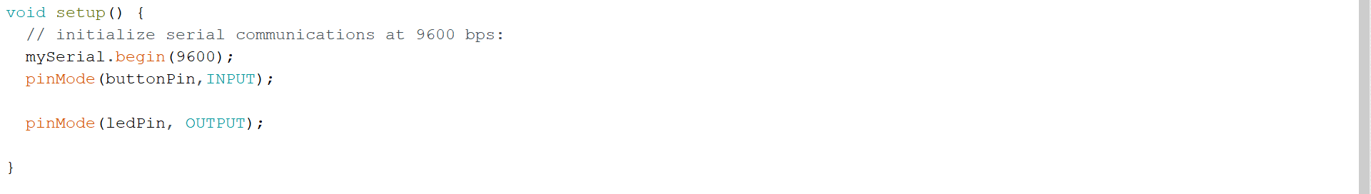
void setup() {
// initialize serial communications at 9600 bps:
mySerial.begin(9600);
pinMode(buttonPin,INPUT);
pinMode(ledPin, OUTPUT);
}
void loop() {
buttonState = digitalRead(buttonPin);
if (buttonState == 1)
{
digitalWrite(ledPin, LOW);
mySerial.write(2);
// mySerial.println("pressed");
delay(50);
} else {
digitalWrite(ledPin, HIGH);
mySerial.write(1);
// mySerial.println("not pressed");
delay(50);
}
}
processing code
as a start, I import the serial library, Next for the icon size I did make it small "size(100, 100);",
now I have to configure the port that I will communicate with "The FTDI port" so I fount this command that prints all the Serial ports that connected to my computer
printArray(Serial.list());
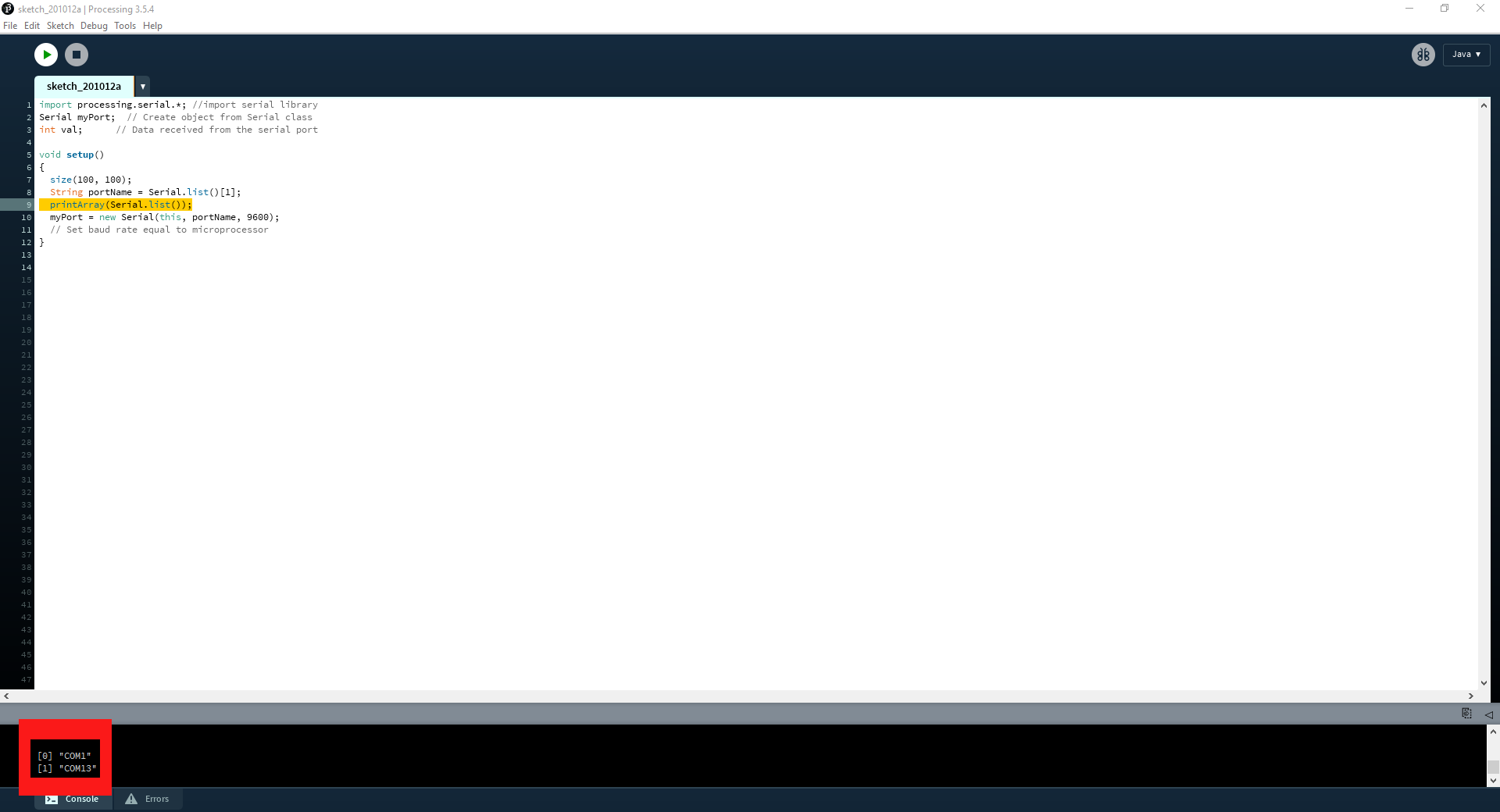
After configuring the port now to set the Set "baud rate" as "9600" we have to make it the same as the Arduino baud rate.
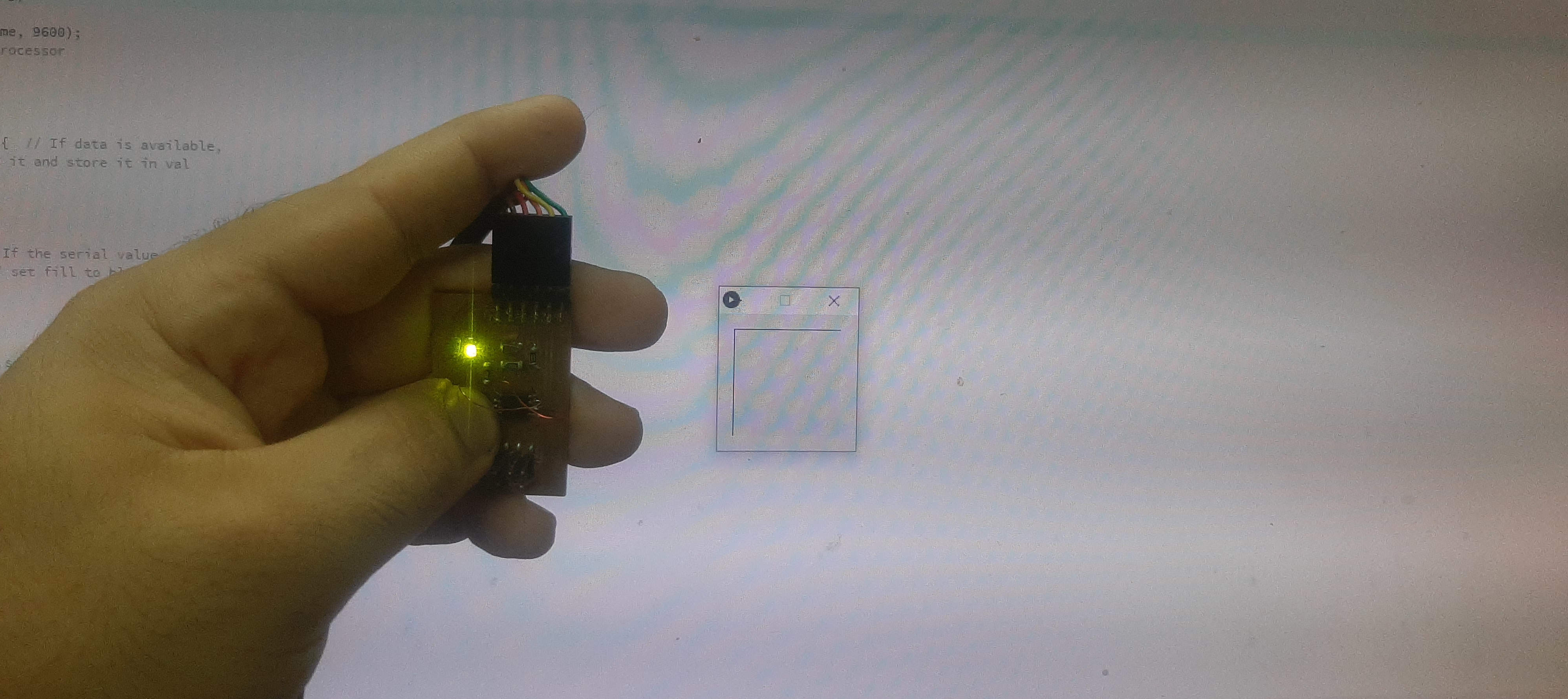
the main code is simple if the value = 1 fill the box with black color if not make fill is with gray easy and simple
so when I hock up the pcb and run the program I had a problem with the pushbutton it didn't react when I bush it and the led was always on, after a lot of thinking the cause of this problem was that the pushbutton and the led was at the same pins as RX and TX, so to solve that real quick I just cut the pins track and connect the pins to another input/output pins and I updated the Arduino code with the modifications.
now the led turn on when I trigger the pushbutton, but after running the processing code again to test the bord it worked to send a digit but it only send zero I trayed to modify the Arduino code multiple times and I didn't go anywhere even I tried to send only 1 to the serial directly without the if Condition and it didn't work either.
It's time to turn the bug into Feature so I know when I Treger the pushbutton it sends 0 value, so I should make the value constantly one and I reset it to 0 by triggering the pushbutton.
so all I did is add at the end of the code that "val=1;" to make the value constantly equal to one, and finally it's work.
processing code
import processing.serial.*; //import serial library
Serial myPort;  // Create object from Serial class
int val;      // Data received from the serial port

void setup()
{
  size(100, 100);
  String portName = Serial.list()[1];
  printArray(Serial.list());
  myPort = new Serial(this, portName, 9600);
  // Set baud rate equal to microprocessor
}

void draw()
{
  while ( myPort.available() > 0) {  // If data is available,
    val = myPort.read();   // read it and store it in val
    println(val);

  }
  background(255);
  if (val == 1) {              // If the serial value is 0,
    fill(50);                   // set fill to black
  }

  else if (val == 0) {
// If the serial value is not 0,
    fill(214);                 // set fill to light gray
     val=1;

  }
  rect(0 , 0, 100, 100);

      delay(300);
}