Embedded programming
Group Assignment:
- Compare the performance and development workflows for different microcontroller families
- Document your work (in a group or individually)
Individual Assignment:
- Read the datasheet for the microcontroller you are programming
- Program the board you have made to do something, with as many different programming languages and programming environments as possible.
My perspective for this week
- Start with Arduino IDE and try to use fab isp with Arduino IDE
- Go to the next level and try to program with embedded c
Group assignment.
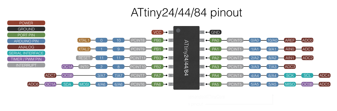
Read datasheet of ATtiny24/44/84
- The following is the main features-:
- High Performance, Low Power AVR® 8-Bit Microcontroller
RISC Architecture - 2/4/8K Bytes of In-System Programmable Program Memory Flash
- 128/256/512 Bytes of In-System Programmable EEPROM
- 128/256/512 Bytes of Internal SRAM
- One 8-Bit and One 16-Bit Timer/Counter with Two PWM Channels
10-bit ADC - Universal Serial Interface
- In-System Programmable via SPI Port
- Internal Calibrated Oscillator
- Available in 20-Pin QFN/MLF & 14-Pin SOIC and PDIP
- Operating Voltage:2.7 – 5.5V
- Speed Grade: 0 – 20 MHz @ 4.5 – 5.5V
I use ATtiny44 microcontroller, it has 4K Flash program memory, 256 of In-system Programmable EEPROM, and 256 Bytes Internal SRAM.
Arduino IDE
So to make everything easy for myself I will start with Arduino because it’s the basic and easy start. So as a start I will begin with the Arduino Language Reference to begin to remember and know more about the basic functions.
Now I will start with writing a basic code turn the led on, it didn’t take much time to write the code,
So after writing my code I figured out that I don’t need to explain the commands besides most of the code is English words and it will be easy to understand as you can see, but anyway I will write what every fountain will do in the comments beside the code.
void setup()              // here we set the pin input or output
  {

 pinMode(PA7, OUTPUT);   // set the digital pin as output:
 pinMode(PA6, OUTPUT);   // set the digital pin as output:
 pinMode(PA1, OUTPUT);   // set the digital pin as output:
 pinMode(PA2, OUTPUT);   // set the digital pin as output:
  }

void loop()   // here is where you'd put code that needs to be running all the time.
{

digitalWrite(PA7, HIGH);    // turn the led on
digitalWrite(PA6, HIGH);    // turn the led on
digitalWrite(PA1, HIGH);    // turn the led on
digitalWrite(PA2, HIGH);    // turn the led on
delay (500);

}
So now for the tricky part flashing the code to Arduino using my fabISP.
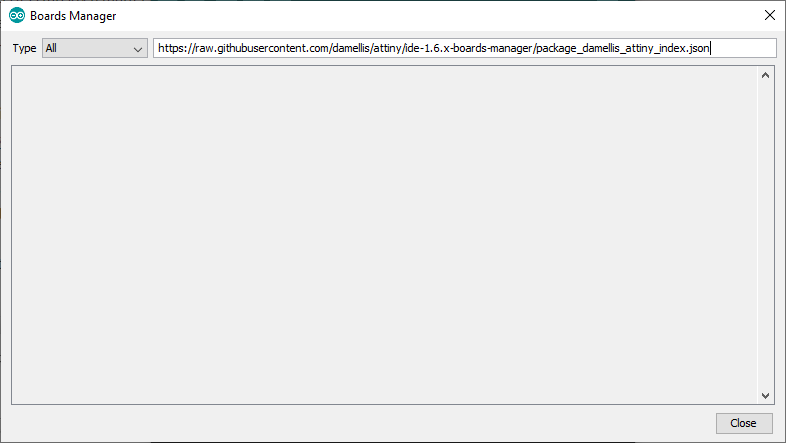
First I need to download the ATTINY library so I can compile and program the code directly from Arduino IDE, So I started with opening the “boards manager” from “Tools > boards > boards manager”
And I typed the ATTINY first nothing next I coped the Github link of this board package but still nothing.
After a little bit of searching on the Arduino forum, I found out that I can add “Additional boards” from “Files > Preferences > Settings > Additional Boards Manager URLs: ”, next is to add the Github URL.
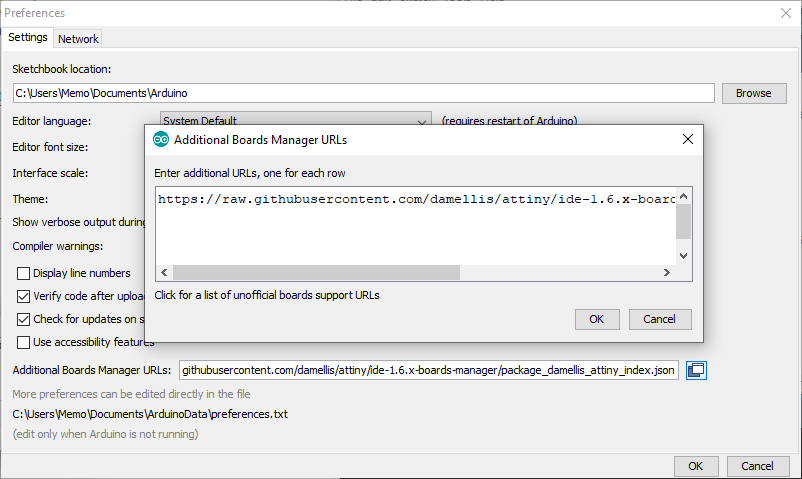
Last is to go to the board manager again and type ATTINY and you will find the library just download the last version of the library.
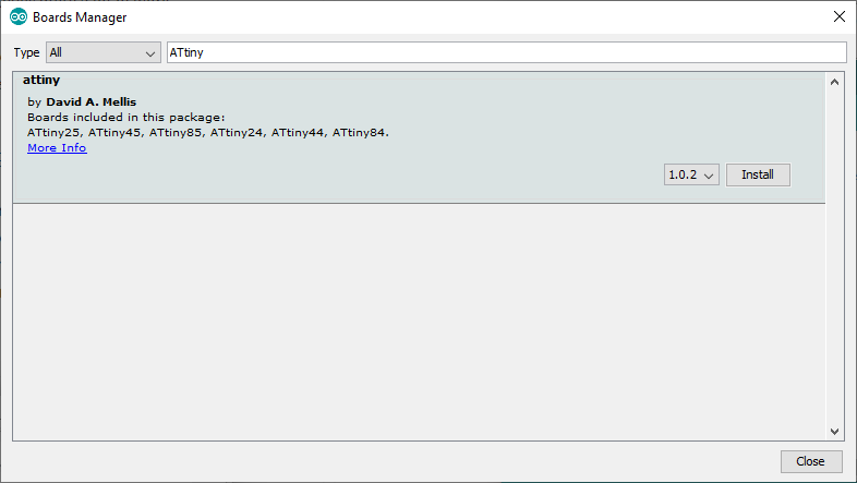
Now after selecting the ATTINY board “attiny44” and clock that I will work with “Internal 1 MHZ ” and now to hook the fabISP and send the code.
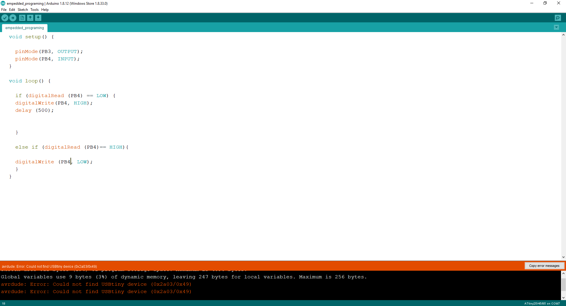
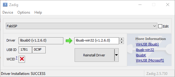
Now I get a new error “cannot find the USBtiny drive” so after asking Nada & Lamia the graduated student from the past year, they asked me if I installed the ISP driver ?!, so when I used the fabISP on Ubuntu I didn’t install any kind of driver so I think that will be the same at windows but no, now to install the driver first I need no install a program called “Zadig” and set the driver options as you can see in the pic.
Last is to upload the code and finally, it worked
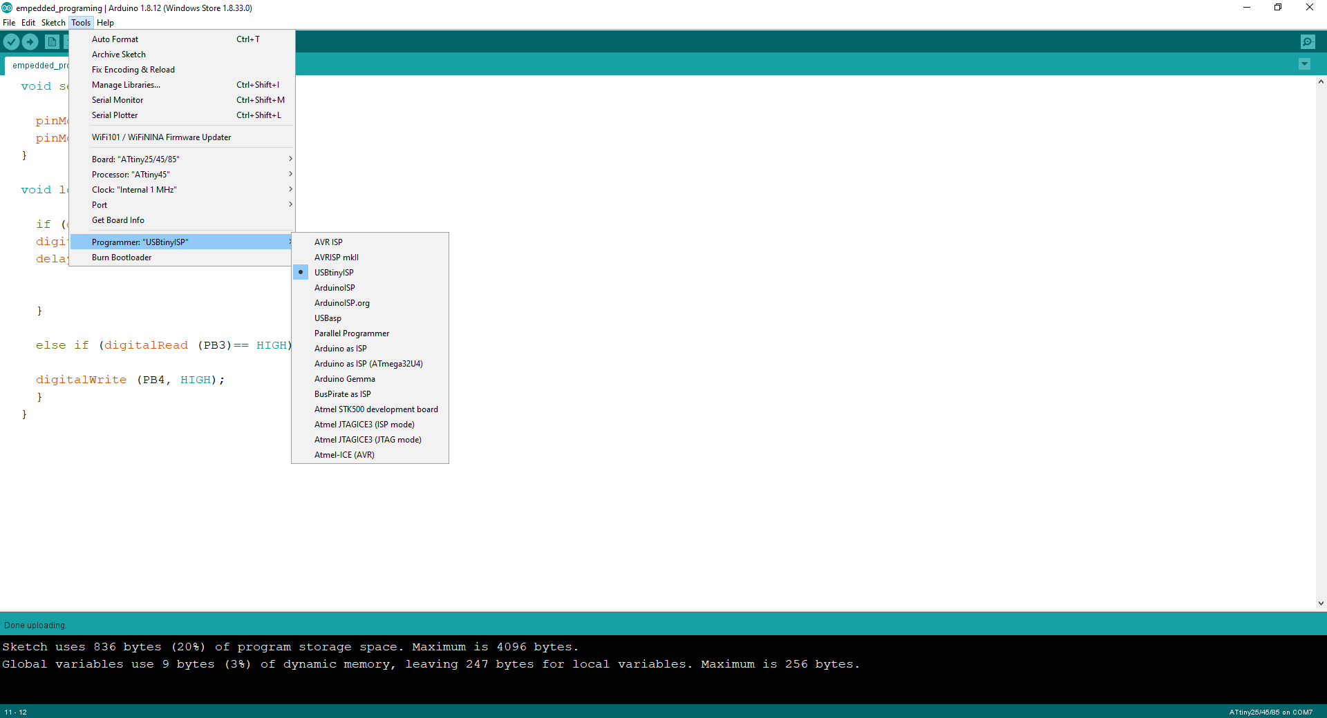
Note
I forget a step so to use the fabISP you need to select “USBtinyISP” so you can send the code through the fabISP
Now with the final result.
Next to right the code I wrote a code to turn the LED on/off using the pushbutton
void setup()  // here we set the pin input or output
{

pinMode(PA7, OUTPUT);  // set the digital pin as output
pinMode(PA6, OUTPUT);  // set the digital pin as output
pinMode(PA1, OUTPUT);  // set the digital pin as output
pinMode(PA2, OUTPUT);  // set the digital pin as output
pinMode(PA0, INPUT);  // set the digital pin as input
}

void loop()  // here is where you'd put code that needs to be running all the time.
{

if (digitalRead (PA0) == LOW)   // check if the pushbutton is pressed. If it is, the buttonState is HIGH:
{
digitalWrite(PA7, HIGH);  // turn the led on
digitalWrite(PA6, HIGH);  // turn the led on
digitalWrite(PA1, HIGH);  // turn the led on
digitalWrite(PA2, HIGH);  // turn the led on
delay (500);
}

else if (digitalRead (PA0)== HIGH) // check if the pushbutton is pressed. If it is, the buttonState is LOW:
{


digitalWrite(PA7, LOW);  // turn the led off
digitalWrite(PA6, LOW);  // turn the led off
digitalWrite(PA1, LOW);  // turn the led off
digitalWrite(PA2, LOW);  // turn the led off

}
}
Ok, and the Push-button worked as expected and now everything looks great.
so I was just messing with the code and I ended up with this X"D
Embedded c
For this, I will use avrdude to program the pushbutton PCB .
First I need to install avrdude “avr-gcc” open terminal and type "sudo apt-get install avr-gcc avr-dude"
I will program my Hello board with attiny 45 this time you can find it in Electronic Design Week
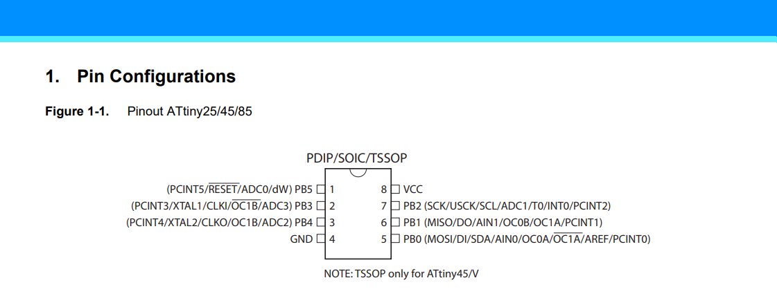
now for the code, I need to reed the attiny datasheet , NOTE :- surely I didn’t read all of them, I just have to look for important information such as.
Pin Configuration:- This shows the functions of each pin.
Programming using FabISP in C language
So to be sure that everything is ok I will write basic code to make sure that the led work fine and make sure there is no problem with the attiny chip.
	#ifndef F_CPU

	#define F_CPU 8000000UL // 8 MHz clock speed

	#endif


	#include  //Library to handle avr inputs and outputs

	#include  // Library to add delays. Necessary for blinking.


	int main(void)

	{

	DDRB = DDRB | (1 << PB3);      // DDRB Port B Data Direction Register. Selects direction of pins

	// In this case PB2 is an ouptut

	DDRB = DDRB & ~(1 << PB4);      //Set PA7 as input

	while (1)

	{

	//Check if button is pressed (its value is 0 because the button has a PULL-UP resistor)

	uint8_t val = PINB & (1 << PB4);

	if(!val){


	//Turn the LED off

	PORTB = PORTB & ~(1 << PB3);

	}

	else {


	//Turn the LED on

	PORTB = PORTB | (1 << PB3);

	}

	}

	}
Next is to write a Makefile but first what is the makefile
Makefile is a set of commands (similar to terminal commands) with variable names and targets to create object files and to remove them.
In my case, I will set some commands and I will explain what’s every command function
PROJECT=pushbuttonAttiny45 #the name of the project

SOURCES=$(PROJECT).c

MMCU=attiny45

F_CPU = 8000000 #define the used crystal frequency


CFLAGS=-mmcu=$(MMCU) -Wall -Os -DF_CPU=$(F_CPU) #creat set off the parameters for compiler(MCU,clock)


$(PROJECT).hex: $(PROJECT).out

avr-objcopy -O ihex $(PROJECT).out $(PROJECT).c.hex;\ #Copy and translate

avr-size --mcu=$(MMCU) --format=avr $(PROJECT).out #display the used


$(PROJECT).out: $(SOURCES)

avr-gcc $(CFLAGS) -I./ -o $(PROJECT).out $(SOURCES) #Compile "creat" .hex


program-bsd: $(PROJECT).hex

avrdude -p t45 -c bsd -U flash:w:$(PROJECT).c.hex #To upload the code to the MCU


program-dasa: $(PROJECT).hex

avrdude -p t45 -P /dev/ttyUSB0 -c dasa -U flash:w:$(PROJECT).c.hex


program-avrisp2: $(PROJECT).hex

avrdude -p t45 -P usb -c avrisp2 -U flash:w:$(PROJECT).c.hex


program-usbtiny: $(PROJECT).hex

avrdude -p t45 -P usb -c usbtiny -U flash:w:$(PROJECT).c.hex


program-dragon: $(PROJECT).hex

avrdude -p t45 -P usb -c dragon_isp -U flash:w:$(PROJECT).c.hex


program-ice: $(PROJECT).hex

avrdude -p t45 -P usb -c atmelice_isp -U flash:w:$(PROJECT).c.hex
Now to upload the code to the PCB I will type this commands
Compile the code by writing
make -f switch.c.make Configure the fuses by writing
make -f switch.c.make program-usbtiny-fusesUpload the HEX file by writing
make -f switch.c.make program-usbtiny