Electronics Production
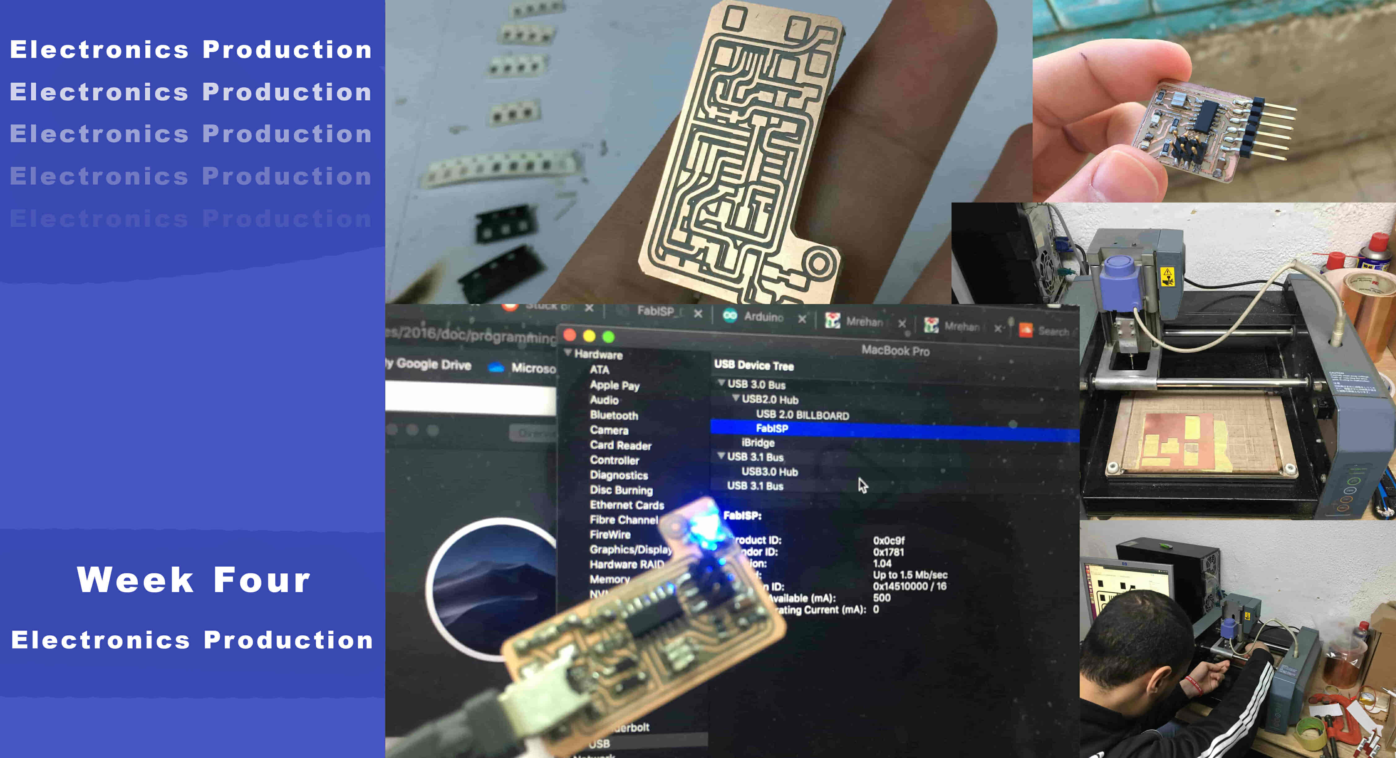
What’s going on?
This week we gonna make an AVR programmer board(we will explain what’s that later). I sent many PCBs to the Fablab to get fabricated but I don’t know the fabrication process itself, I never went through the CNC fabrication process before. It will be my first time to fabricate a PCB board by myself using the PCB milling machine. I’m very excited about that :D
First, let’s agree on some concepts. PCB is a board that contains some lines(Tracks) and pads that connects the components together and allow the electricity(signals and power) to travel from point to another through those tracks without the need to use any external wires or jumpers. This thing makes building electronic devices very robust and more rigid.
Today we gonna make a PCB board called an AVR ISP or an AVR programmer, What’s that programmer thing? Ok, a programmer is an electronic board based on a microcontroller that responsible for sending a program to another microcontroller. The microcontroller used in the programmer board has a firmware uploaded to it that tells that microcontroller “Hey fam, you are working as a programmer ok. Only sending .hex files to other microcontrollers.”
Lemme ask a question, How does These PCBs are get fabricated? There is more than one PCB fabrication method or process, there’s a method that you can follow and make PCBs at home with simple tools and components called the “Acid Etching method”. It’s a subtractive process where acid is used to remove the unwanted copper from a prefabricated board. This is done by printing the tracks and pads(needed copper) on a mask that protects parts of the board from the acid and leaves the desired copper layer untouched. But, there is the problem of waste disposal. Toxic chemicals require a proper disposal service.
There is another method, instead of printing the circuit on a heat transfer paper using a laser printer, The mask is printed on a transparent paper or foil, exposed and developed on the prefabricated board with a UV lamp. Actually, this is the method which is used in the PCB fabrication factories to make mass production.
The previous two methods(Toner transfer & UV transfer) are cool and deserve to experiment with both of them. But, they need some specified tools and chemicals which are not very cool, also each method from the two above requires many steps which is boring and increases the potential to fail besides the toxic nasty chemicals that affect the environment :(
Here comes the most effective and fast method for PCB prototyping from my point of view which is the machining method. Using the CNC milling machine to fabricate your PCB doesn’t require many steps. Just finish your design, export some PNG images, throw it to the fab modules software and finally, send the Gcode to the machine. That’s it!
Characterizing The Machine (Group Assignment)
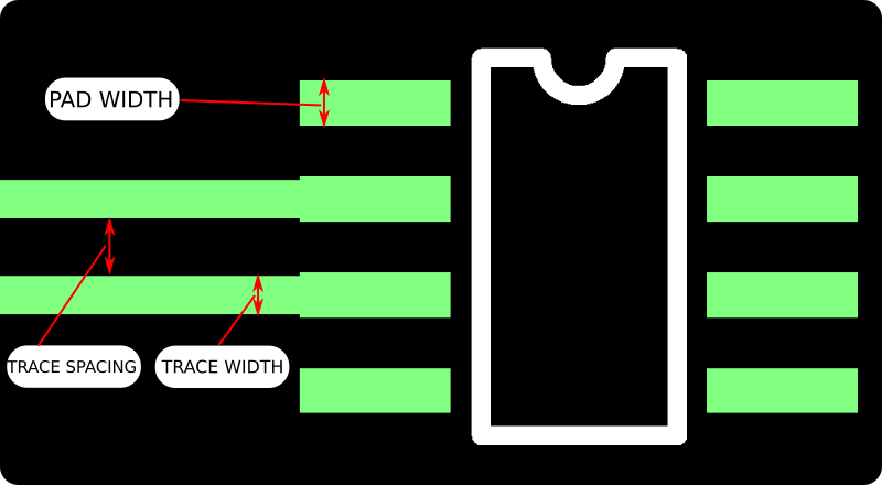
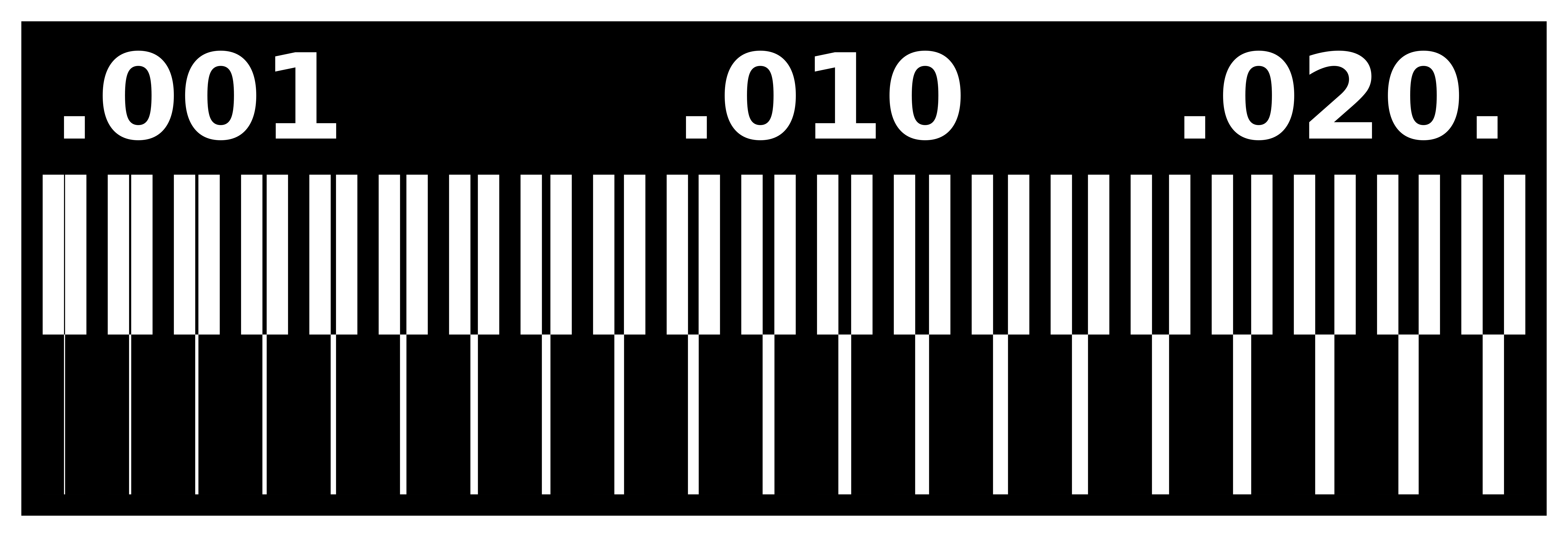
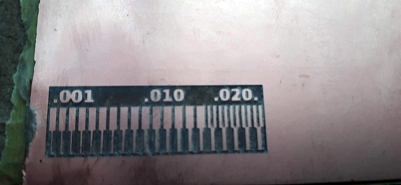
Before we start fabricating our ISP(In-circuit programmer) we need to know well the machine capabilities that we gonna deal with. Let’s start by characterizing the machine by fabricating a test board that will tell us some facts about our machine, like what’s the smallest track width that machine can give us, what’s the smallest clearance that the machine can give us which is the distance between two tracks or between track/pad or pad/pad … etc.
Yo! I have good news for ya ;) someone designed the test board that we gonna use and uploaded the files open-source to anyone. I mean you don’t have to design a new one unless you want to. We can download these files from these links.
"Test" PCB PNG Files Download
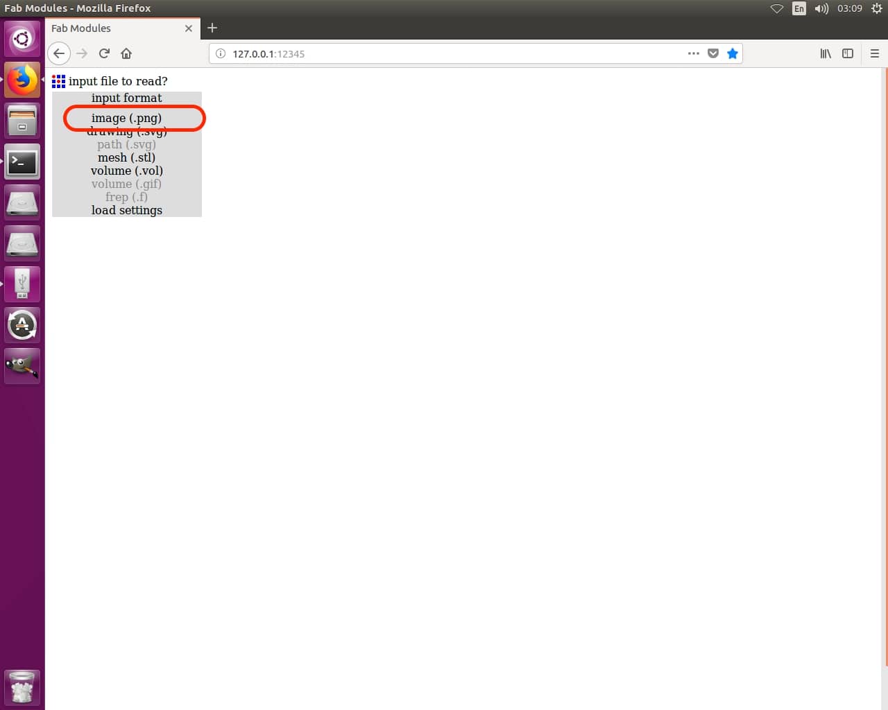
Something strange, Why the PCB files extension is “.PNG” and all of them are in black and white? Ok lemme explain, To fabricate our board we gonna use something called “Fab modules” is a browser-based CAM system, which allows us to generate toolpaths for and control laser cutters, CNC-mills, and waterjets commonly found in fablabs.

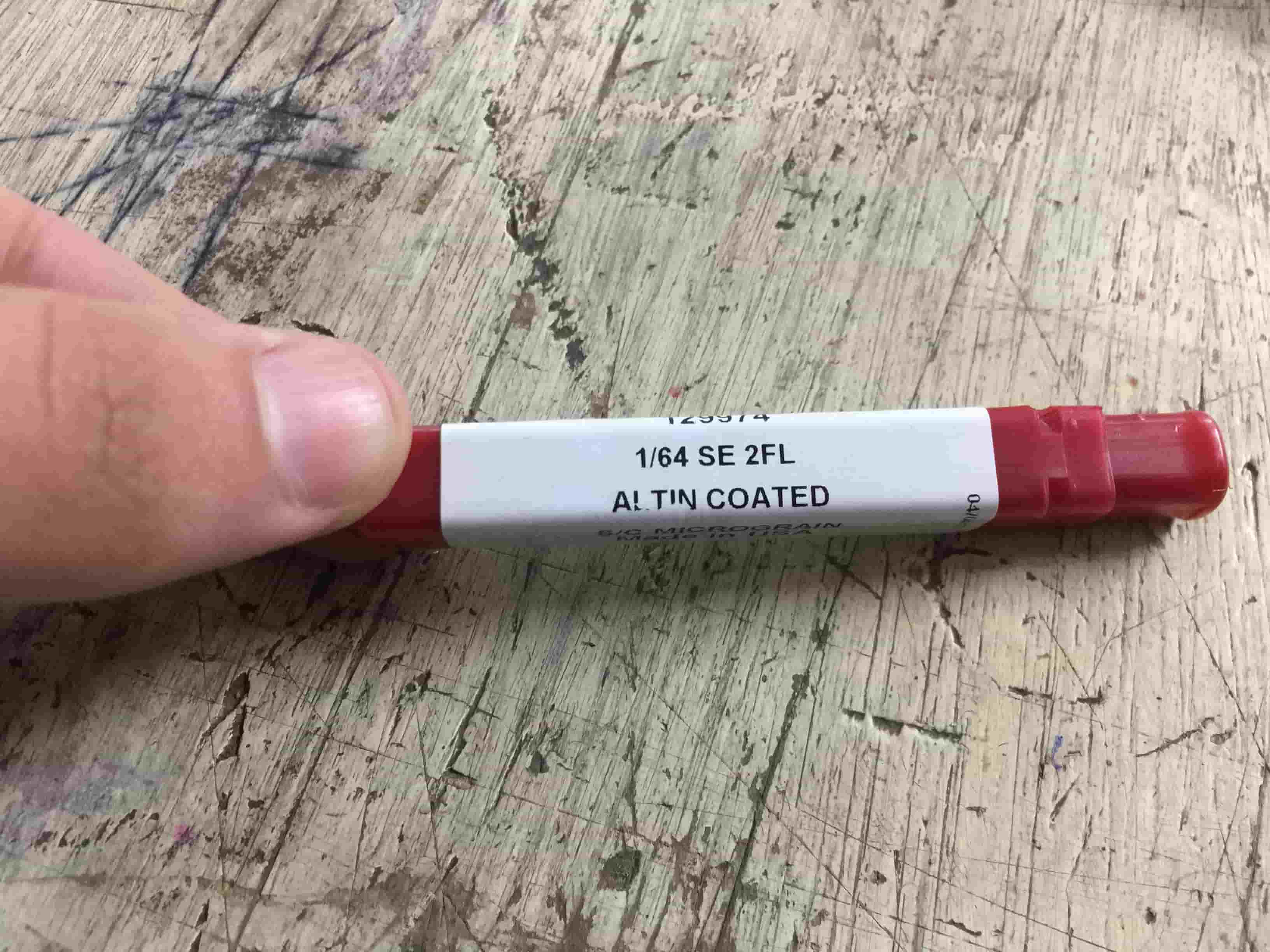
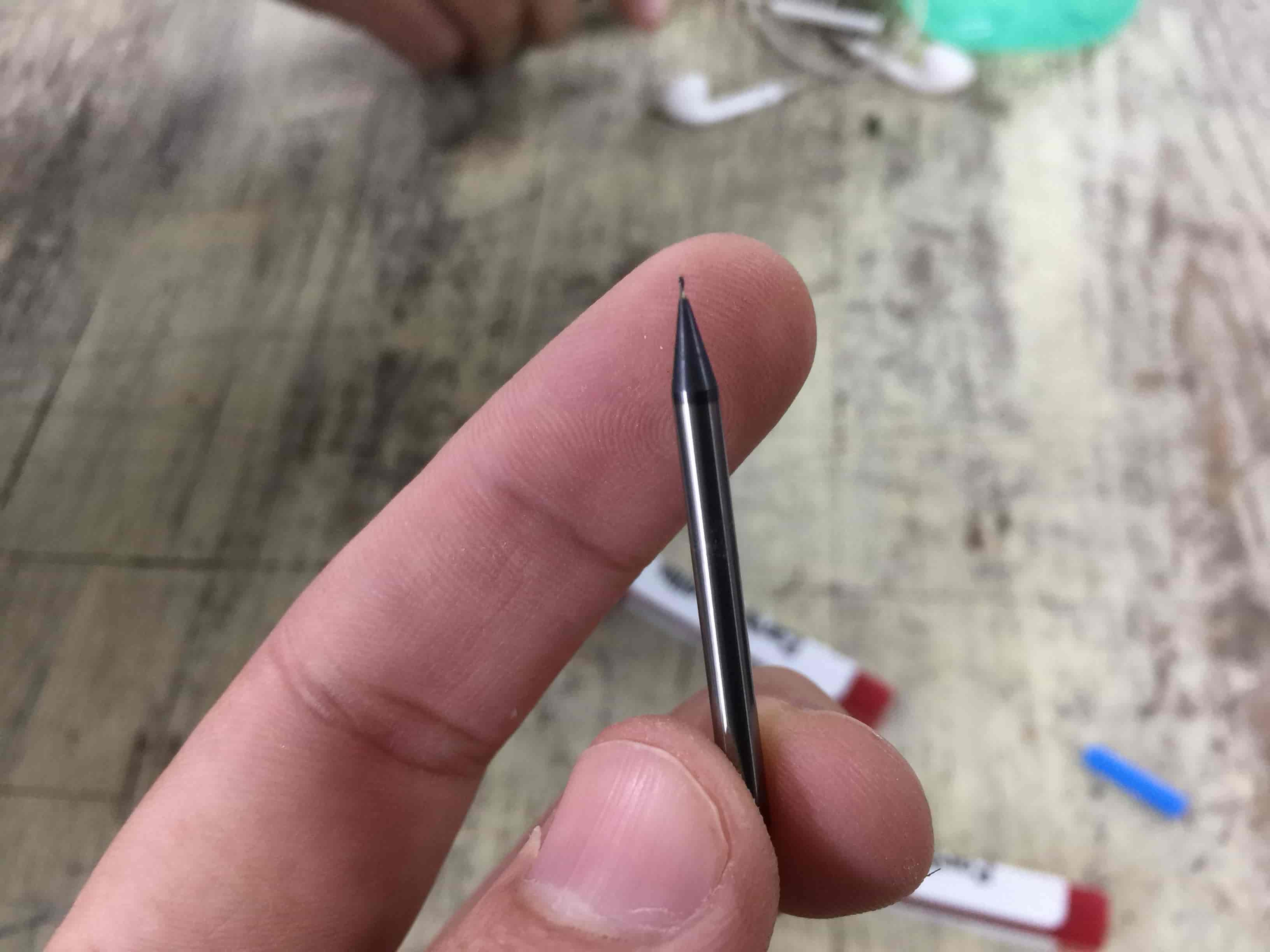
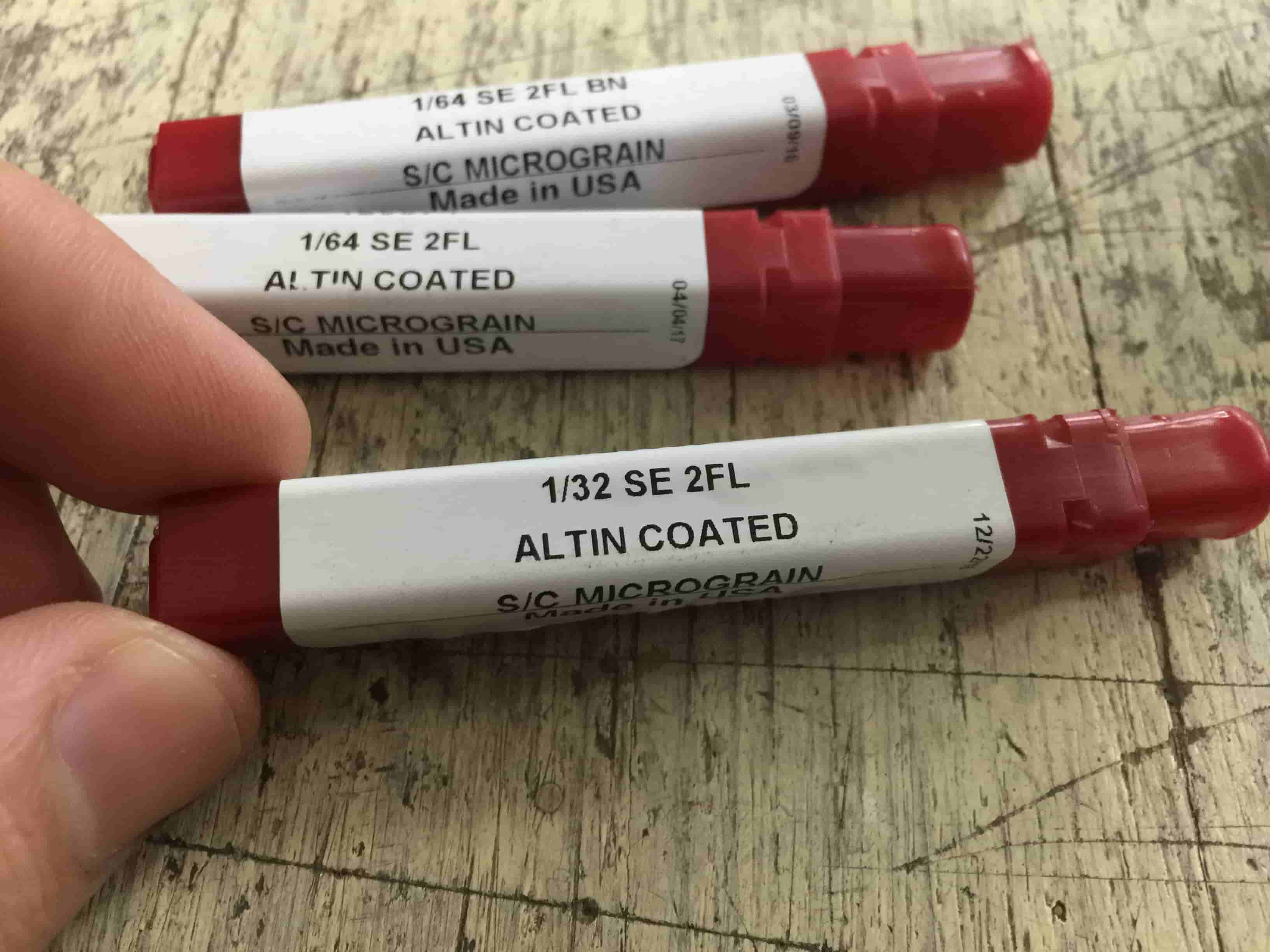
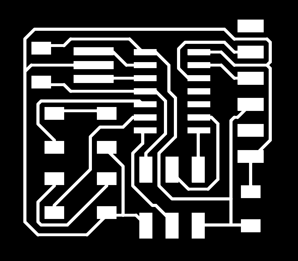
We will fabricate our PCB in two steps, the first step is milling the PCB traces and pads using a 1/64inch endmill, the second step is to drill any holes(if we are using THT components) and cut the PCB outline(Profile) using a 1/32inch endmill. Since we are fabricating our PCB in two different steps, then we need two different files, one for the traces and pads(needed copper), and the other file for the drills and outline cut.
The colors in these files are so important, the machine will mill all the black areas and leave all the white areas. For example, in the traces image, the machine will eat(mill) all the unneeded copper(black area) and leave for us all the needed copper which is our traces and pads(white areas).
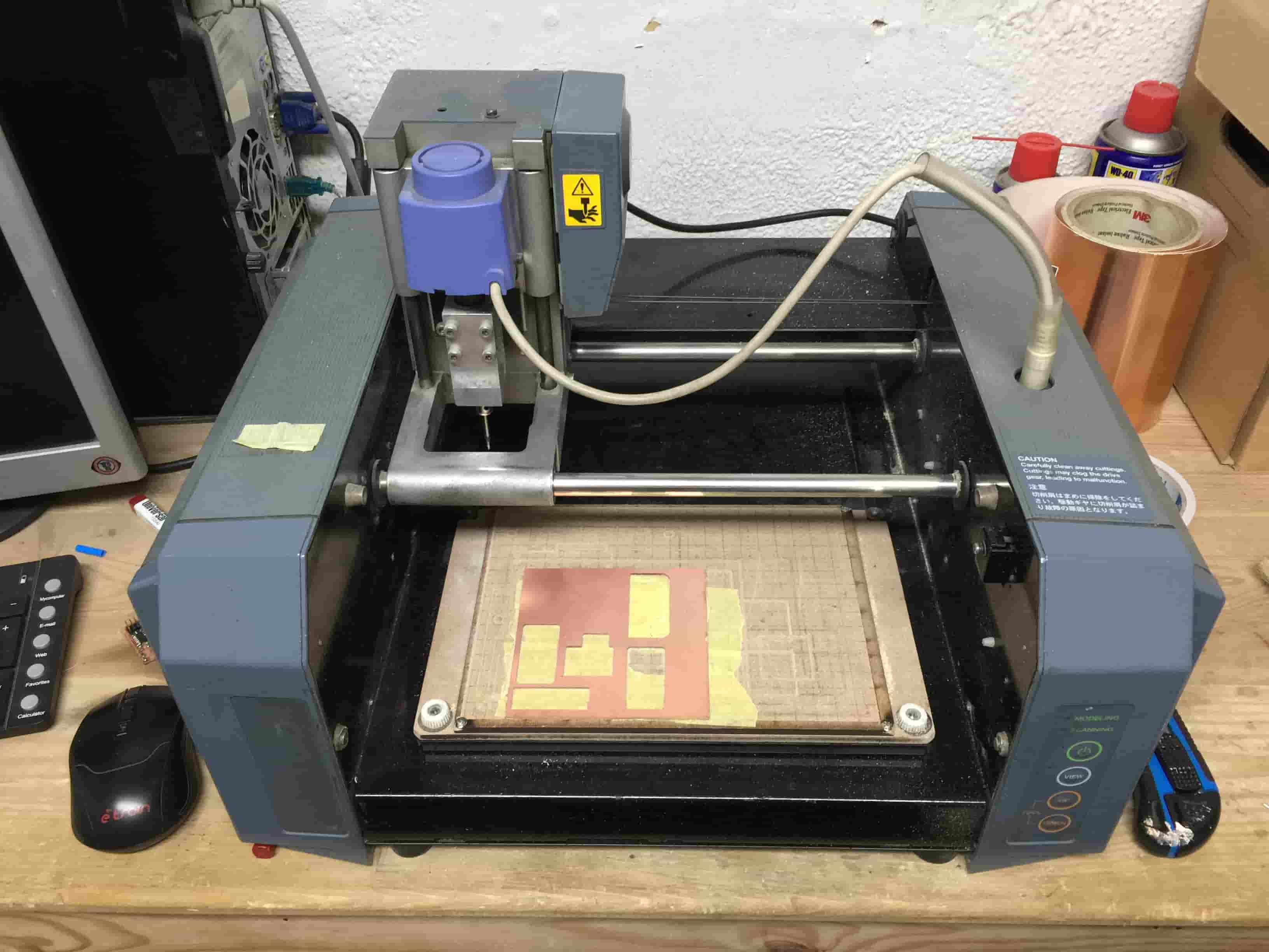
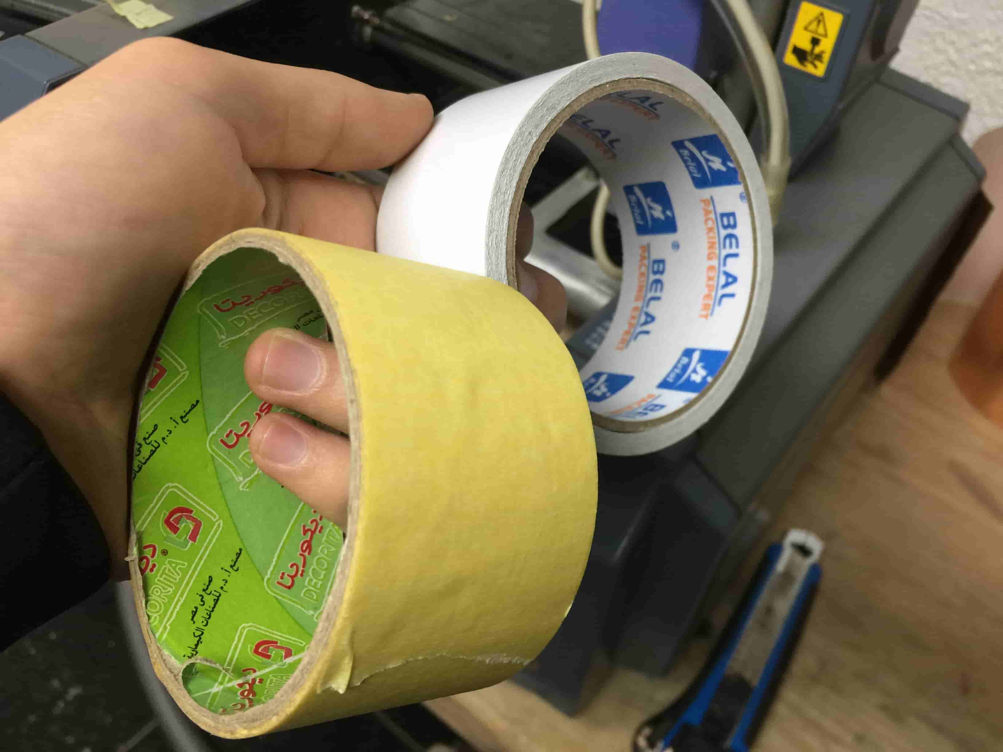
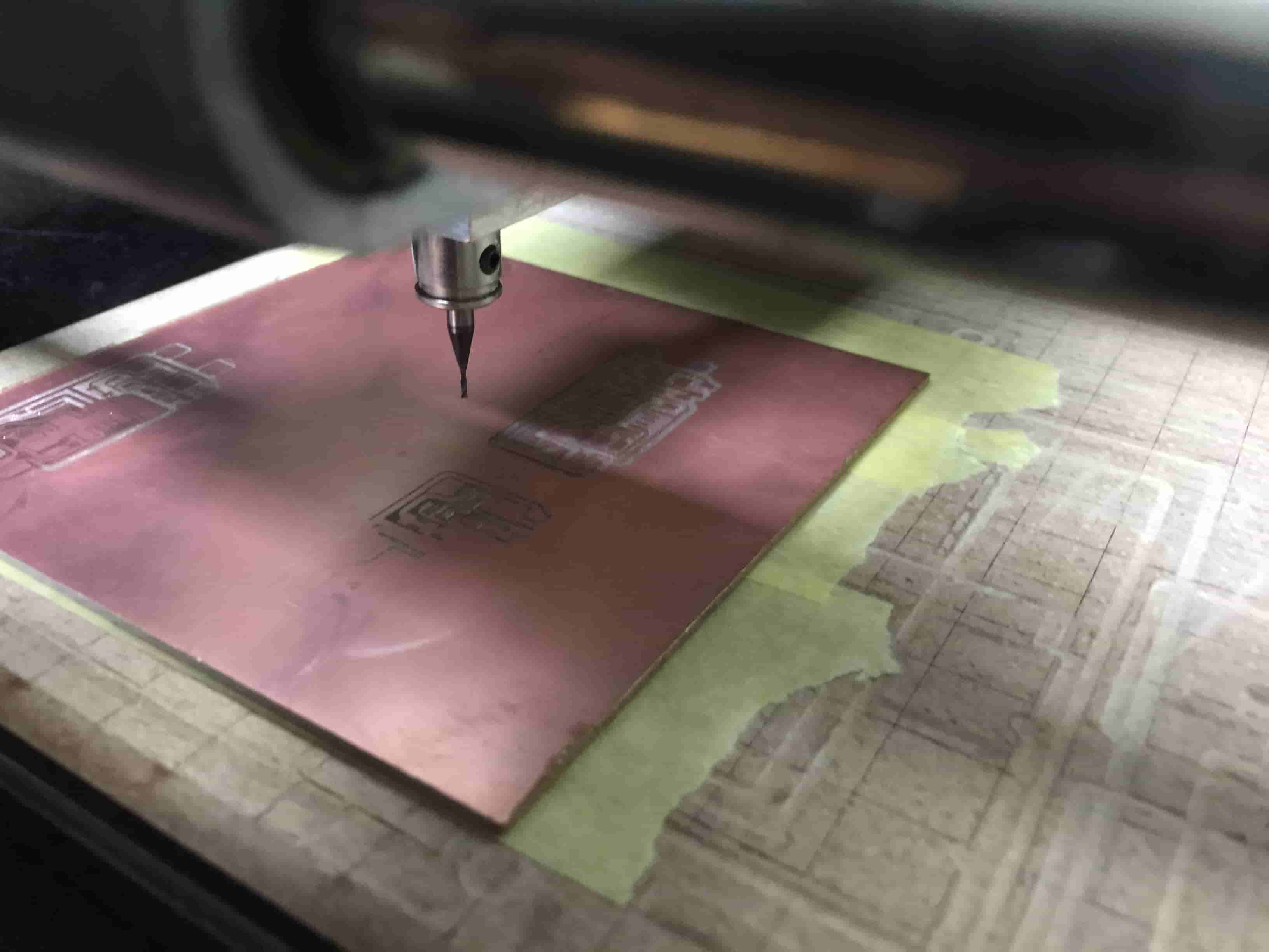
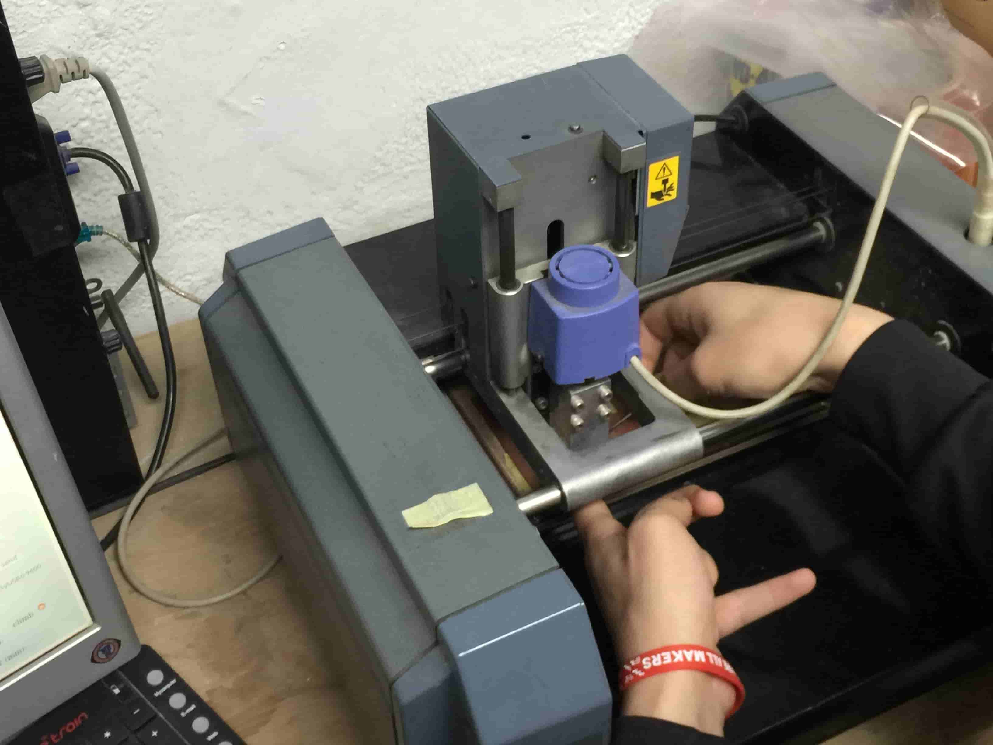
Now, we need to install our PCB properly on the bed of the modela so we can start our job smoothly. The PCB should be very flat on the bed with no elevated sides. If the PCB is not flat on the bed that will cause damage to the endmill. We gonna use a double face tape to fix the PCB on the bed of the machine, put in the consideration that the PCB should be as flat on the bed as possible.
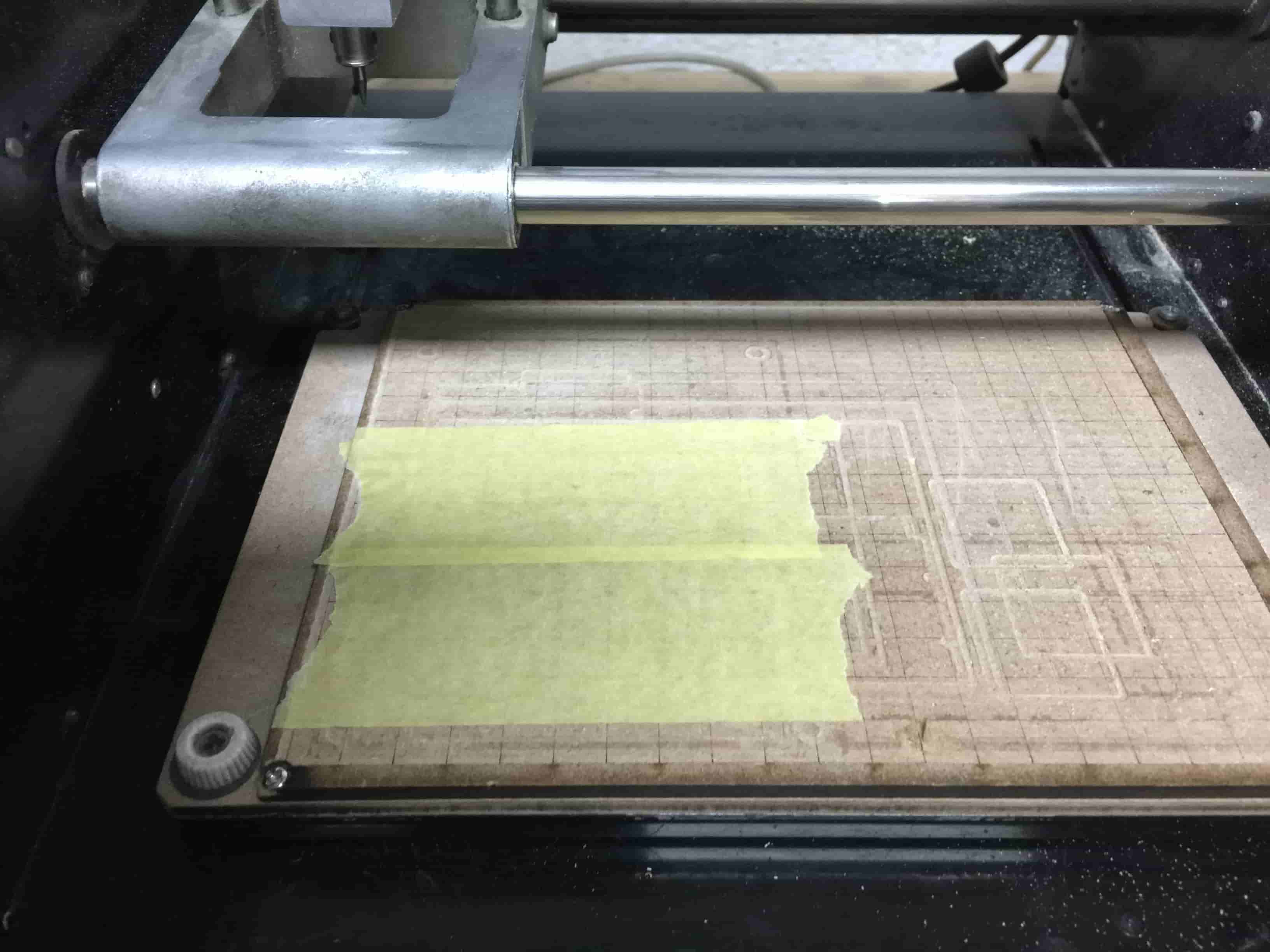
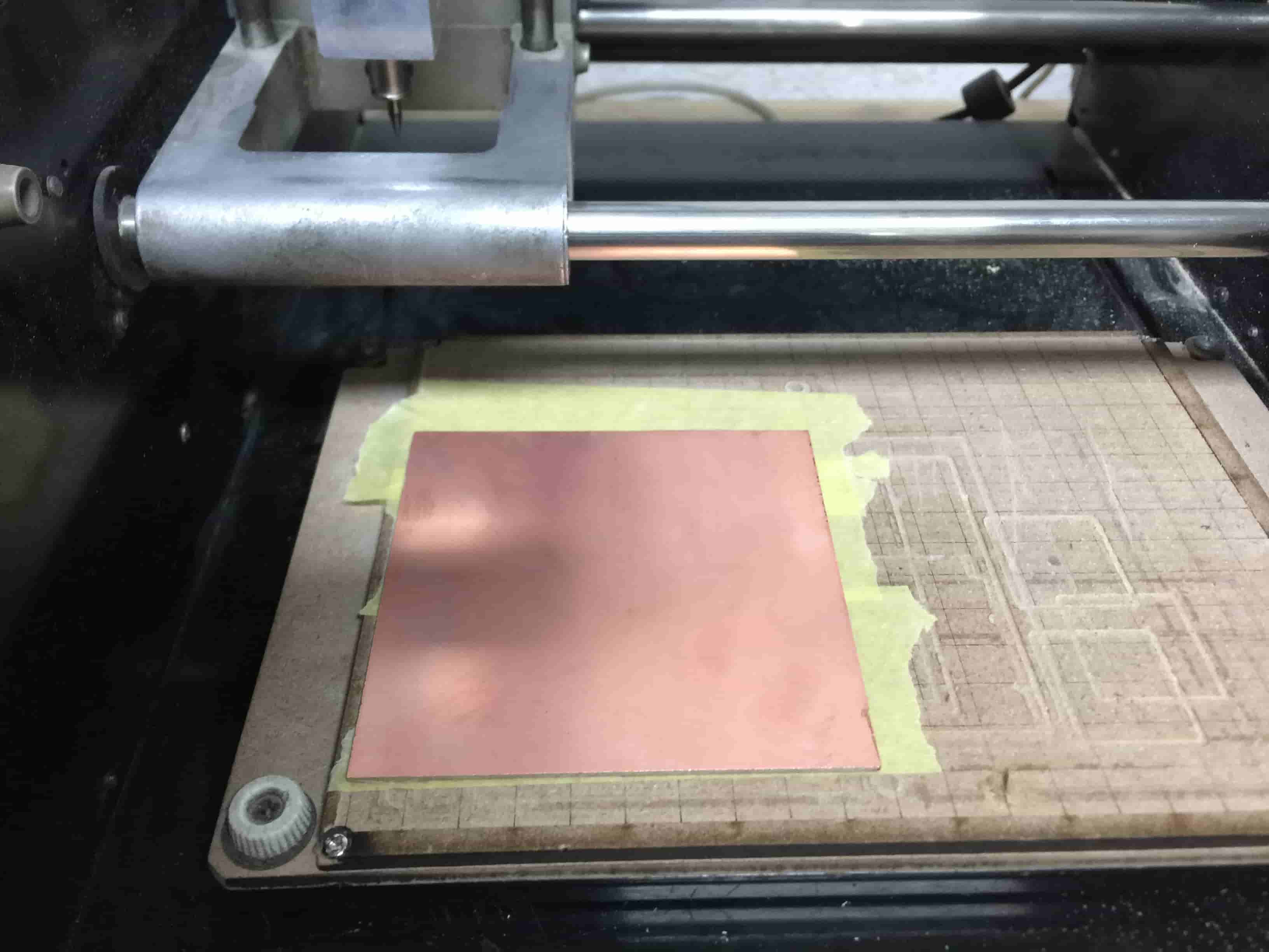
After installing the PCB on the machine bed, we gonna use a 1/64inch endmill to mill the traces of the board.
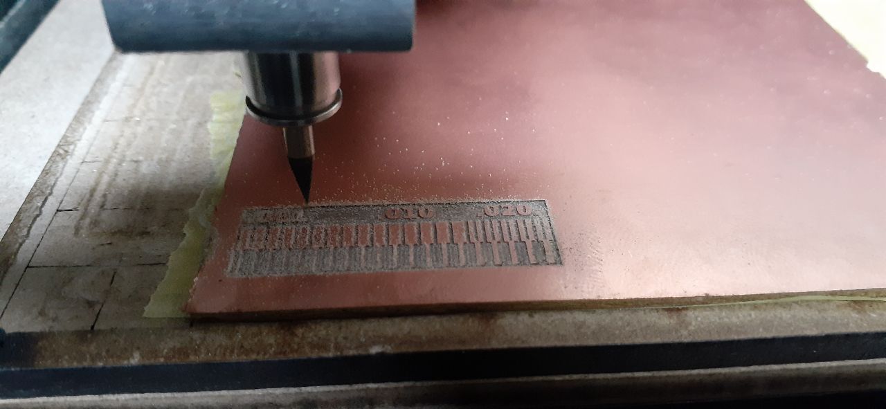
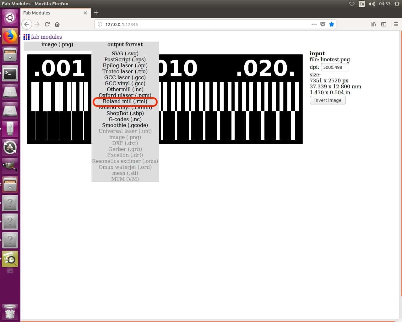
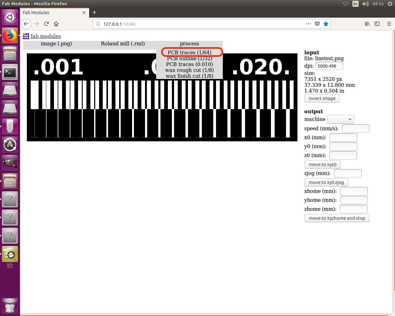
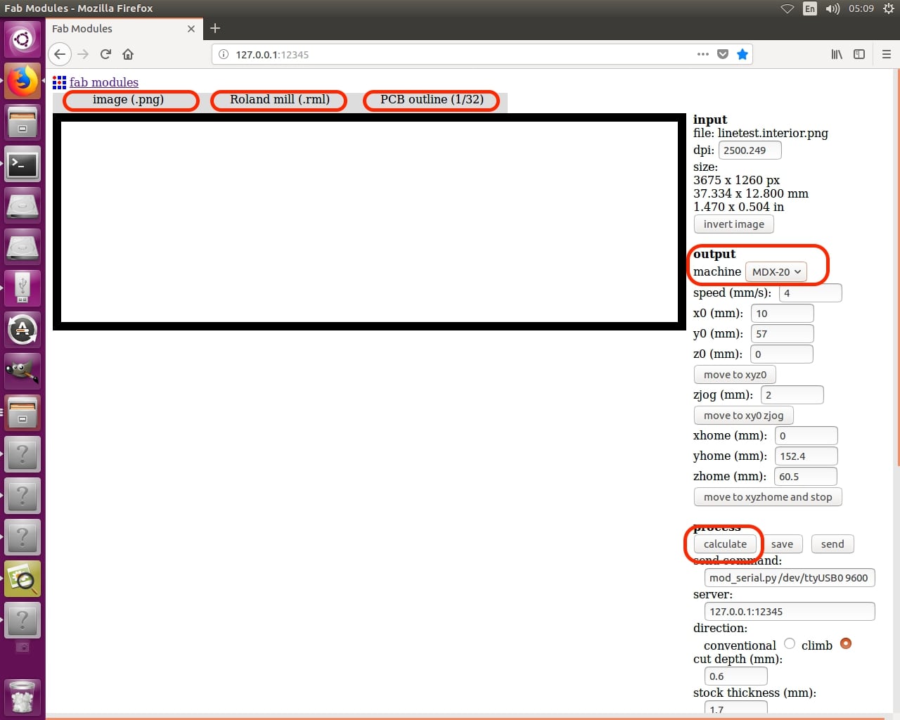
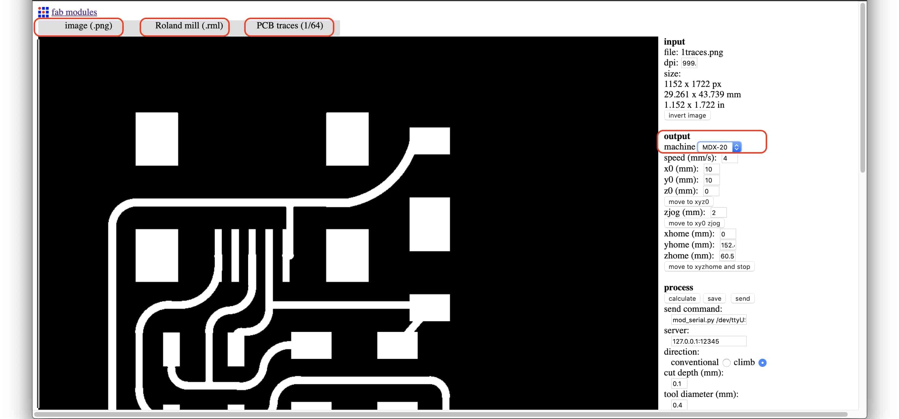
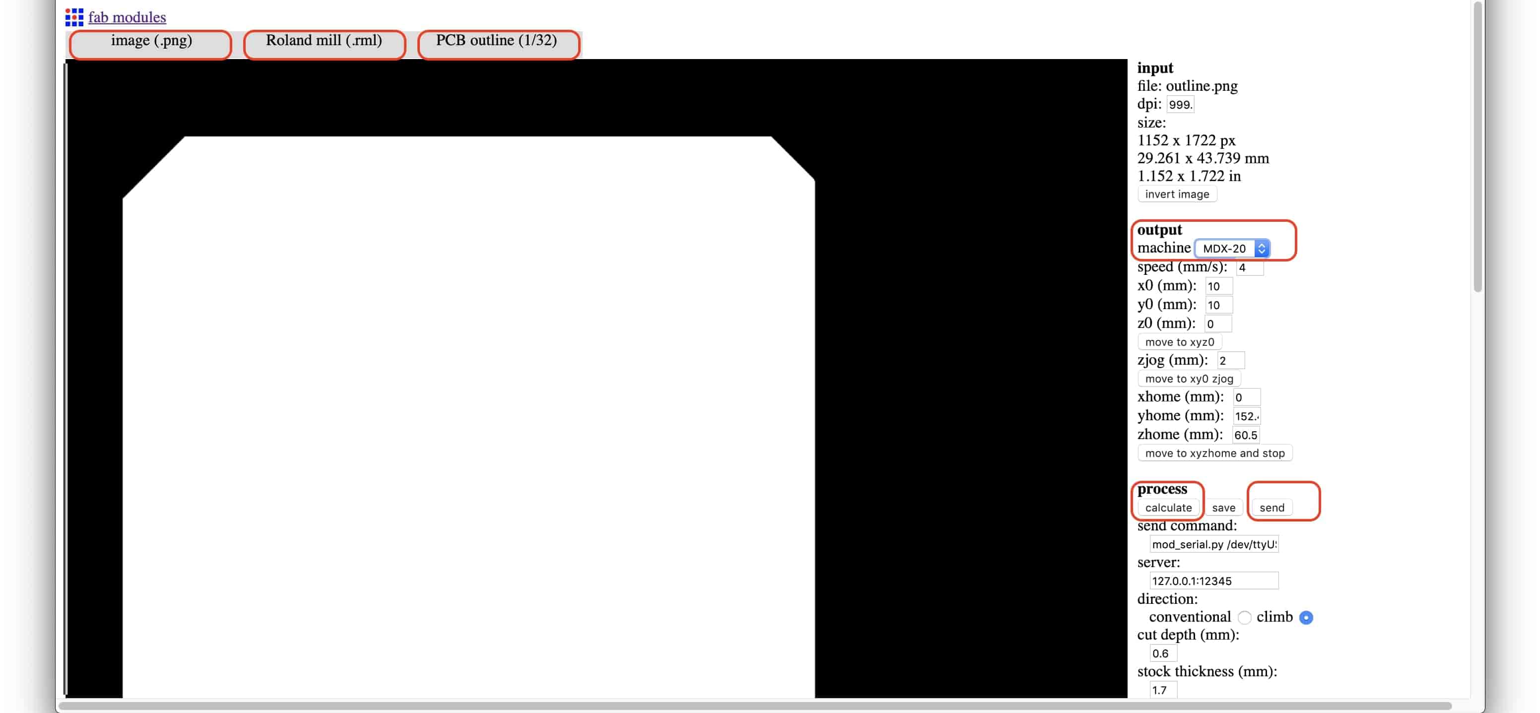
After installing the PCB on the machine bed and the 1/64inch endmill in the machine collet, we gonna open the CAM software(fab modules) that will generate a toolpath for the machine to mill our board. Then we gonna import the traces PNG image, set the output format to Roland Mill, set the process job tp PCB Traces, set the machine to MDX-20 the one we use in Fab Lab Egypt and press Calculate.
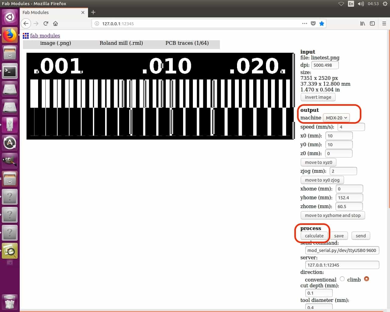
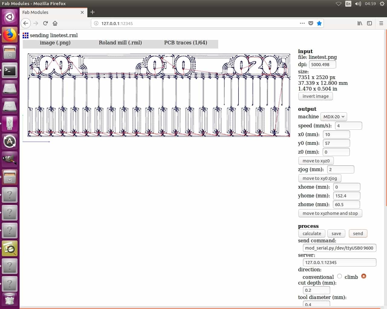
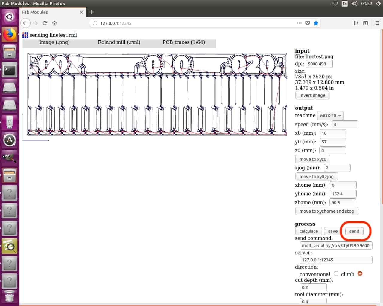
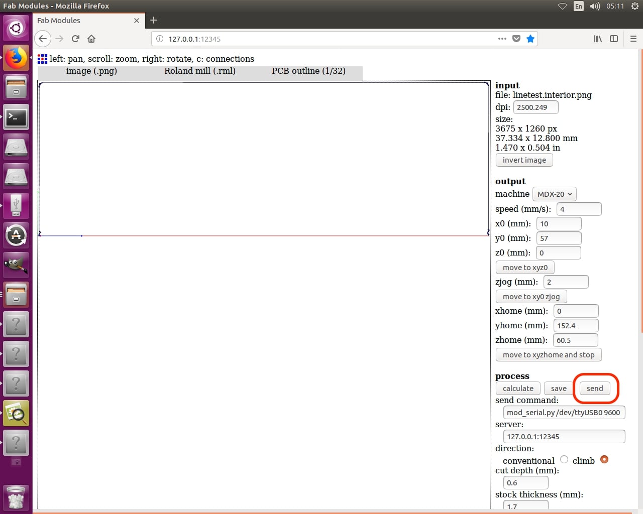
Let the CAM software finish its job, then we're gonna check the toolpath if there’s anything weird like a track not milled or something. If everything is good and satisfying, press send.
After finishing the traces job, we need to cut the outline(Profile) of the PCB. So, we gonna change the used endmill from 1/64inch to the 1/32inch one and repeat the previous steps, import the outline PNG image, set the output format to Roland Mill, set the process job tp PCB Outline, set the machine to MDX-20 the one we use in Fab Lab Egypt and press Calculate then send
Searching for a suitable ISP board
Now, after we saw how to use the PCB milling machine AKA modela and how to use the awesome fab modules to generate the toolpath for the machine, let’s make some search for a suitable and cool ISP. There are a lot of options that Prof Neil mentioned in the lecture
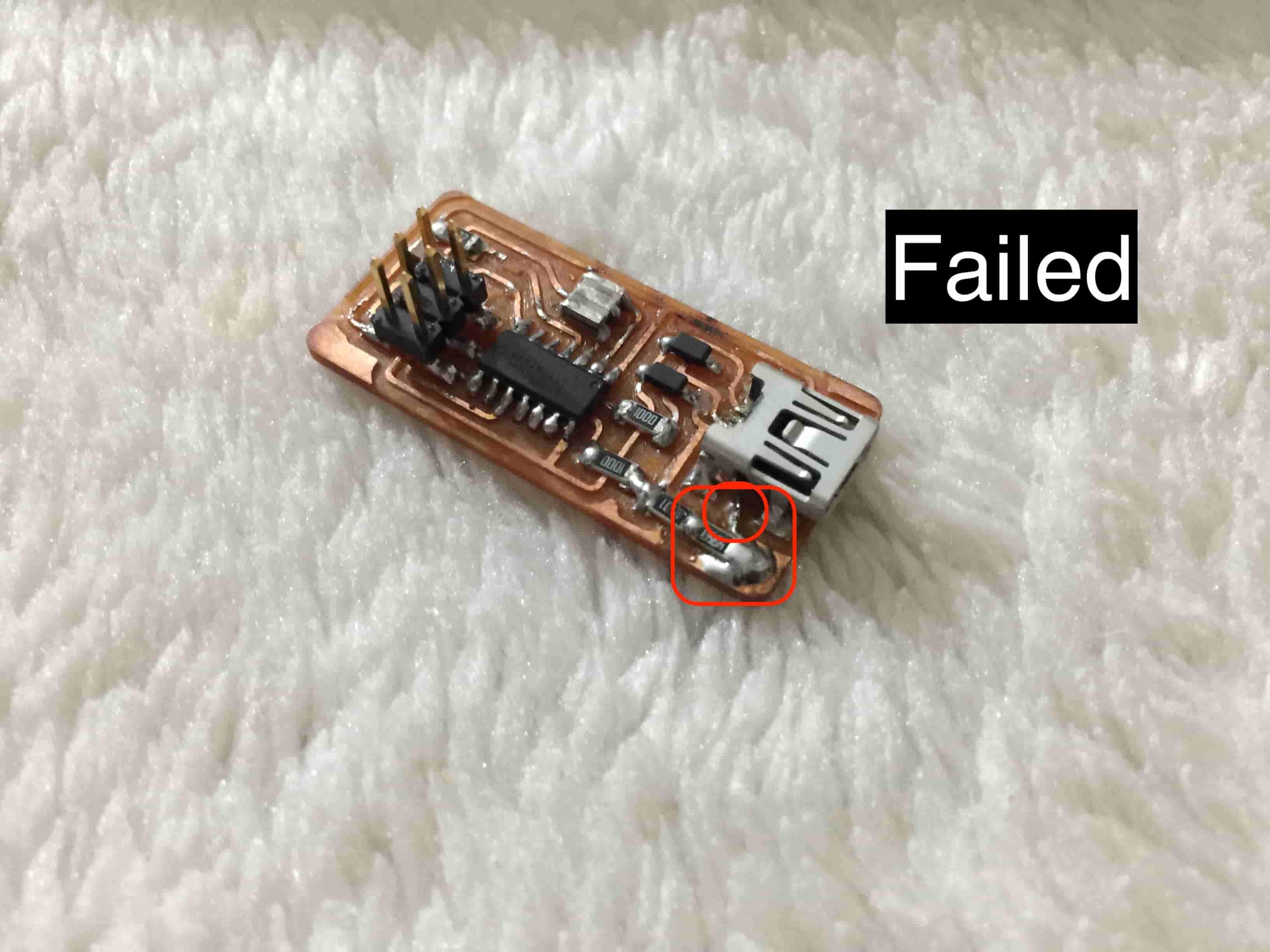
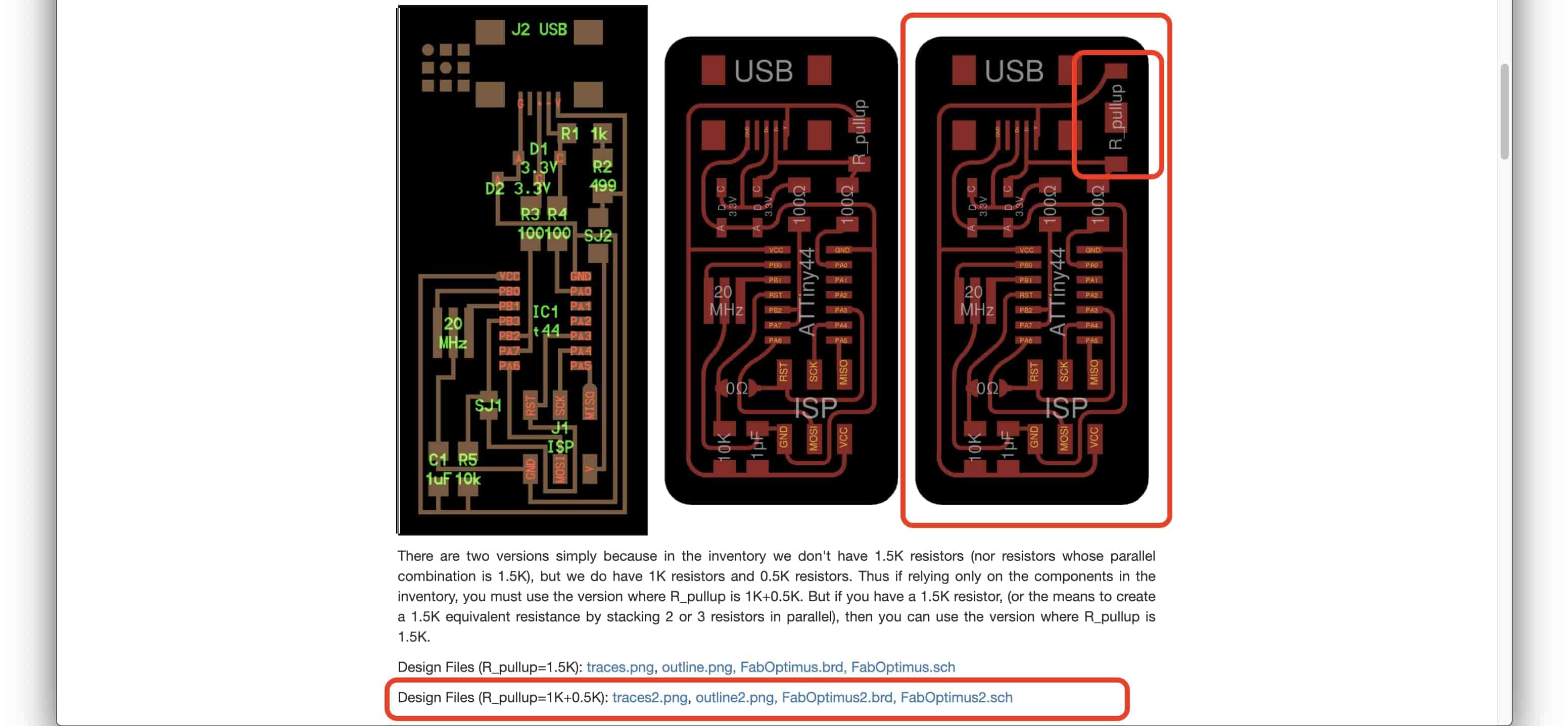
I chose to make the FabOptimus ISP by Ali. he really provided a comprehensive explanation about the design of his board and the concept behind it, also explained why did he use these components specifically which is great. Thanks Ali, he made two versions of this board. One with a single 1.5kohm resistor and the other one with two series resistor 1kohm & 499kohm because in the inventory we don't have 1.5K resistors (nor resistors whose parallel combination is 1.5K), but we do have 1K resistors and 0.5K resistors. So, if you decided to make this board make sure to pick up the right version according to the available components in your lab. At first, I picked the single 1.5kohm resistor board version then I discovered after I fabricated the board that we don’t have 1.5kohm resistor. I tried to make some tweaks to the board like soldering some wires and some other stupid stuff but it all failed :D
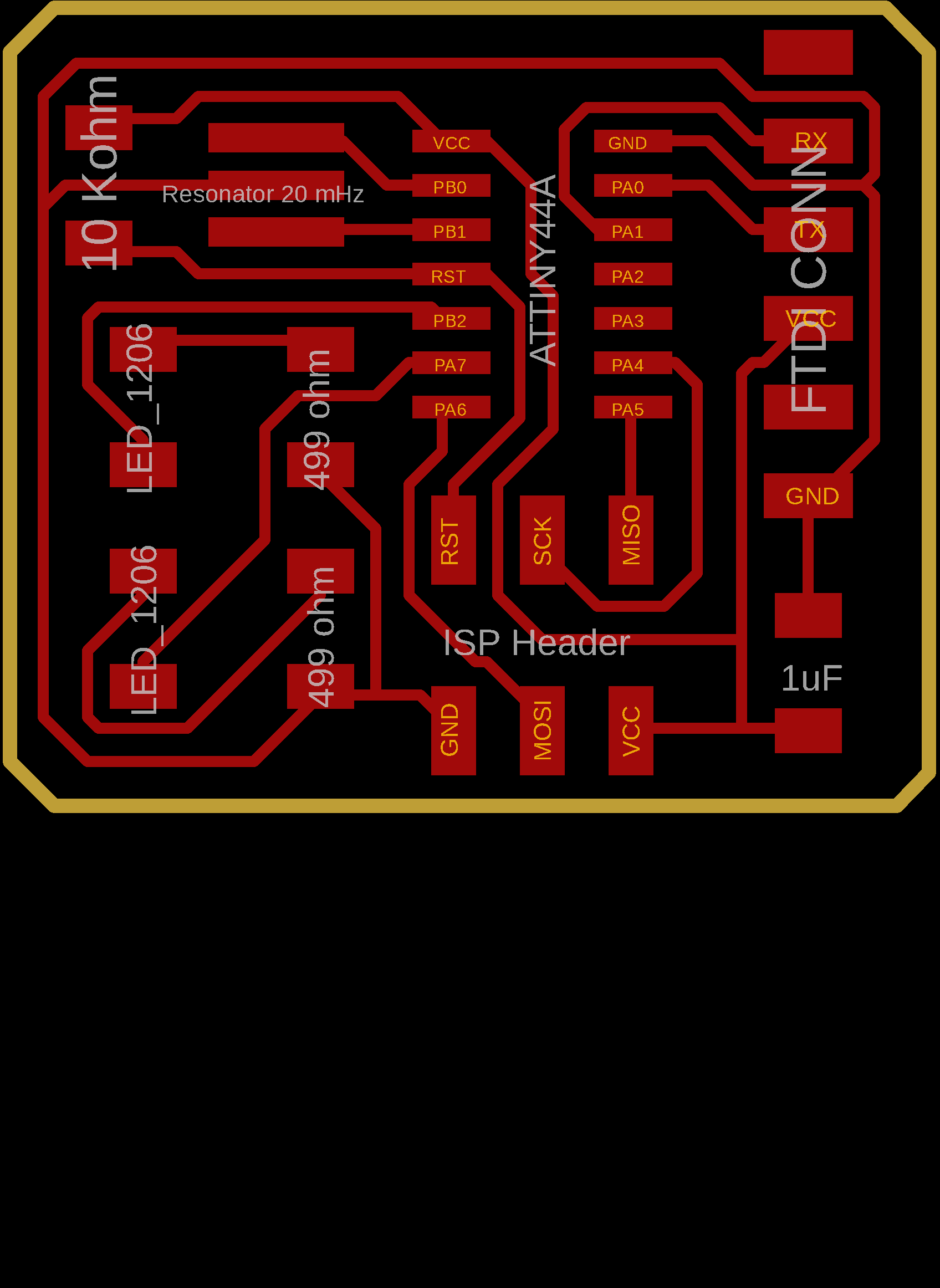
It seems like I have to fabricate the two series resistors version, I downloaded the board traces and outline PNG images and I got sure that we have all the board components in Fab lab Egypt inventory. But before I start fabricating the board, I wanna make an edit on this design! I noticed that the board doesn’t have any LED indicator telling if the board is working or not. So, I decided to add one that will light up when it's working and vice versa.
I downloaded the board .SCH and .brd files and opened them using EagleCAD.
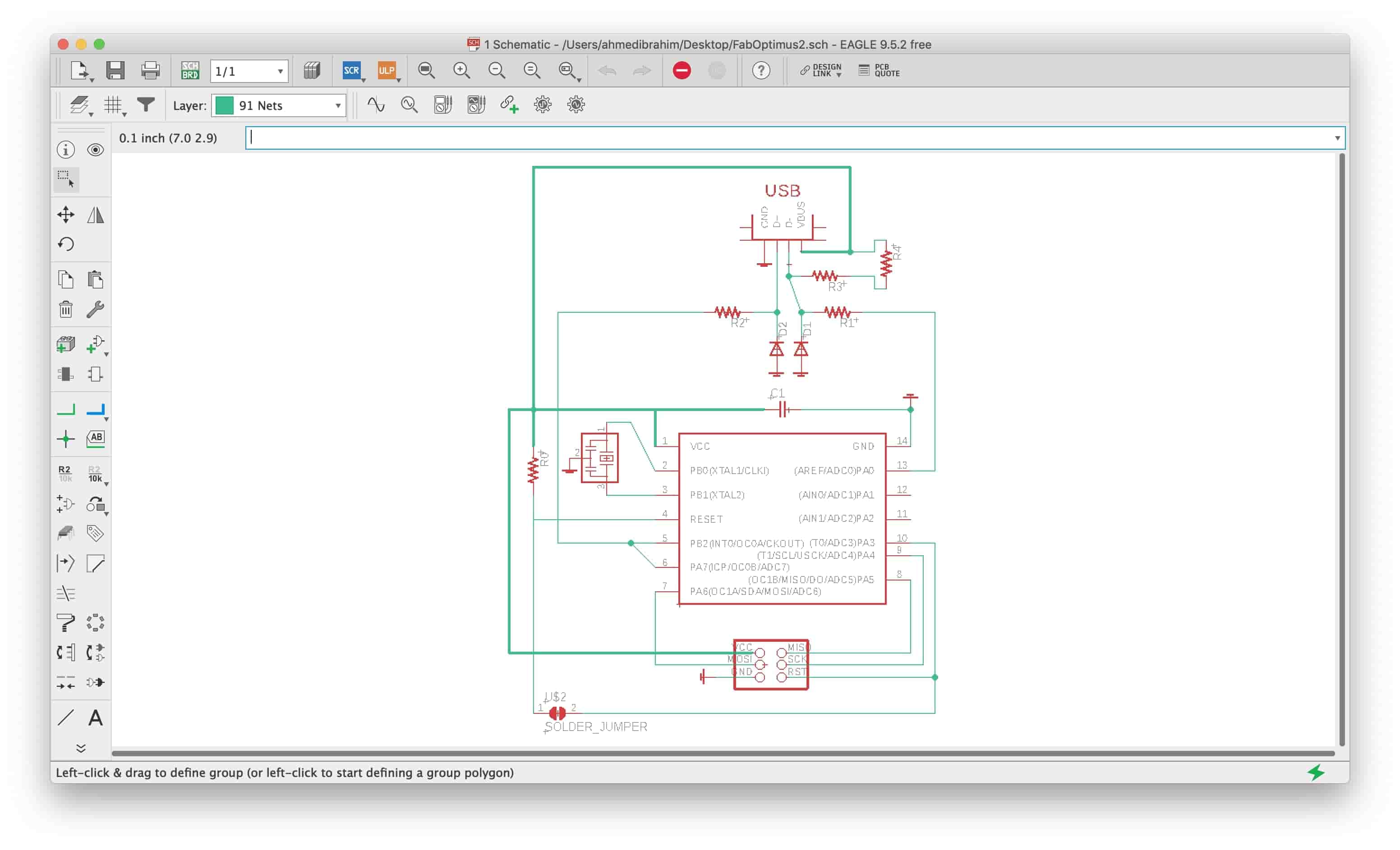
Where exactly should we connect the LED? Since we need the LED to power up when the board gets connected to the computer or laptop. Then, we gonna connect the LED to the input 5V which coming from the USB through a current limiting resistor.
Why do we need a resistor in series with the LED? the LED is actually a simple diode which after a certain amount of voltage drop on its terminals will allow all the available current (unlimited) to flow through it which is not a good idea at all. Here comes the current limiting resistor job is to choke that current flow. If you wanna know how to calculate the resistor value you can check out this link.
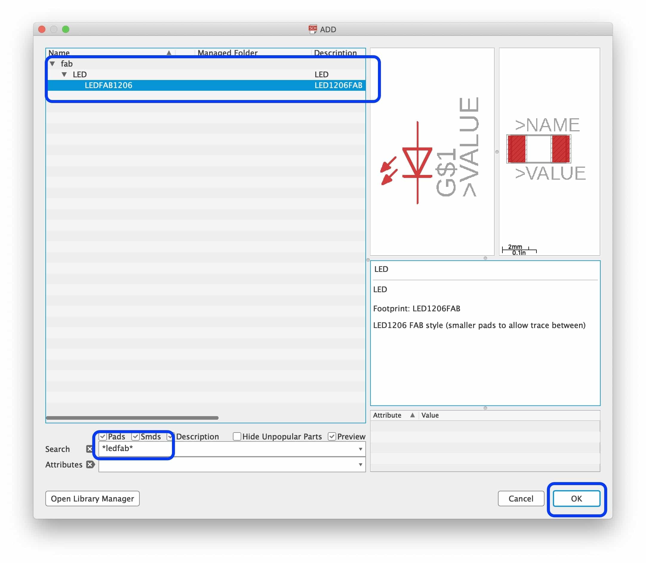
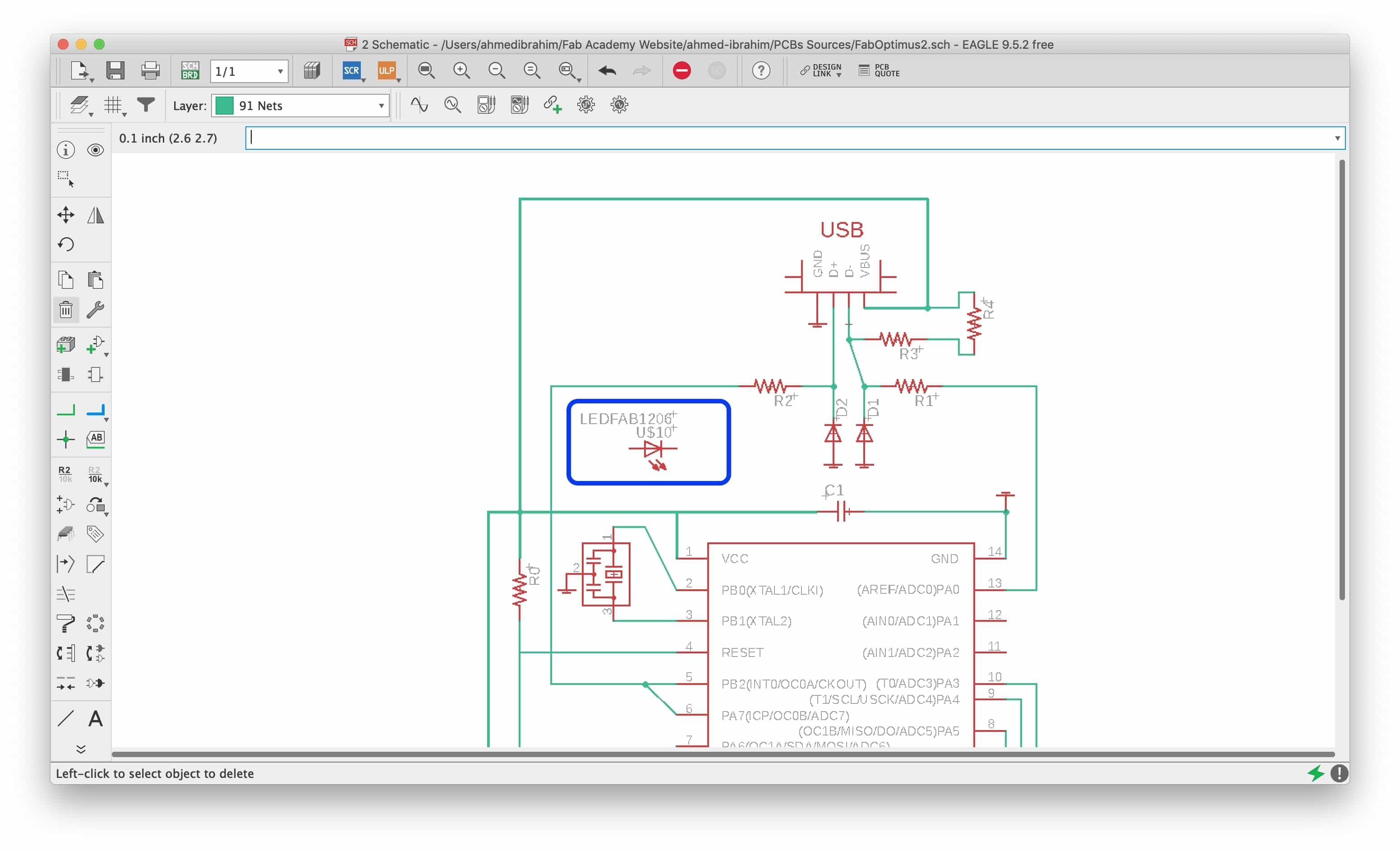
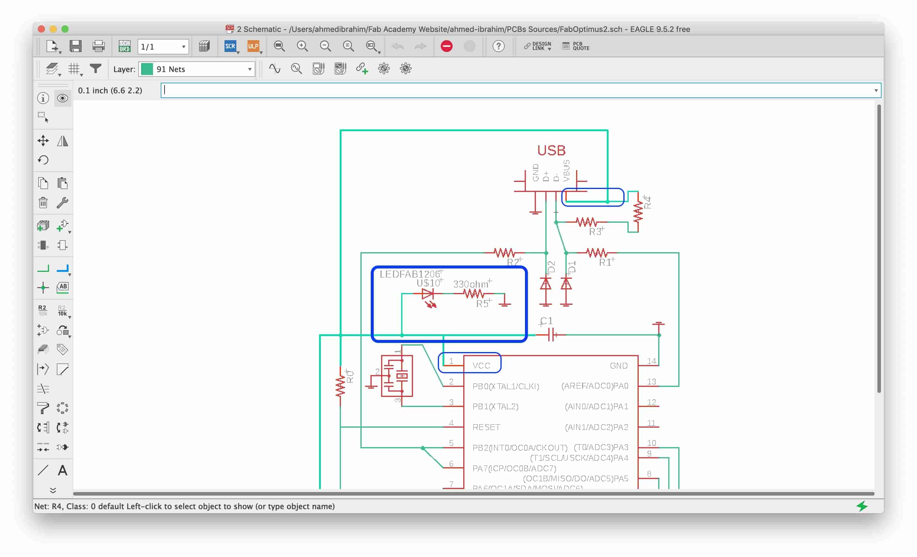
After we planned where should we connect the LED in the circuit, From the “Add tool” in EagleCAD, search for “*ledFAB*” and insert it in your design.
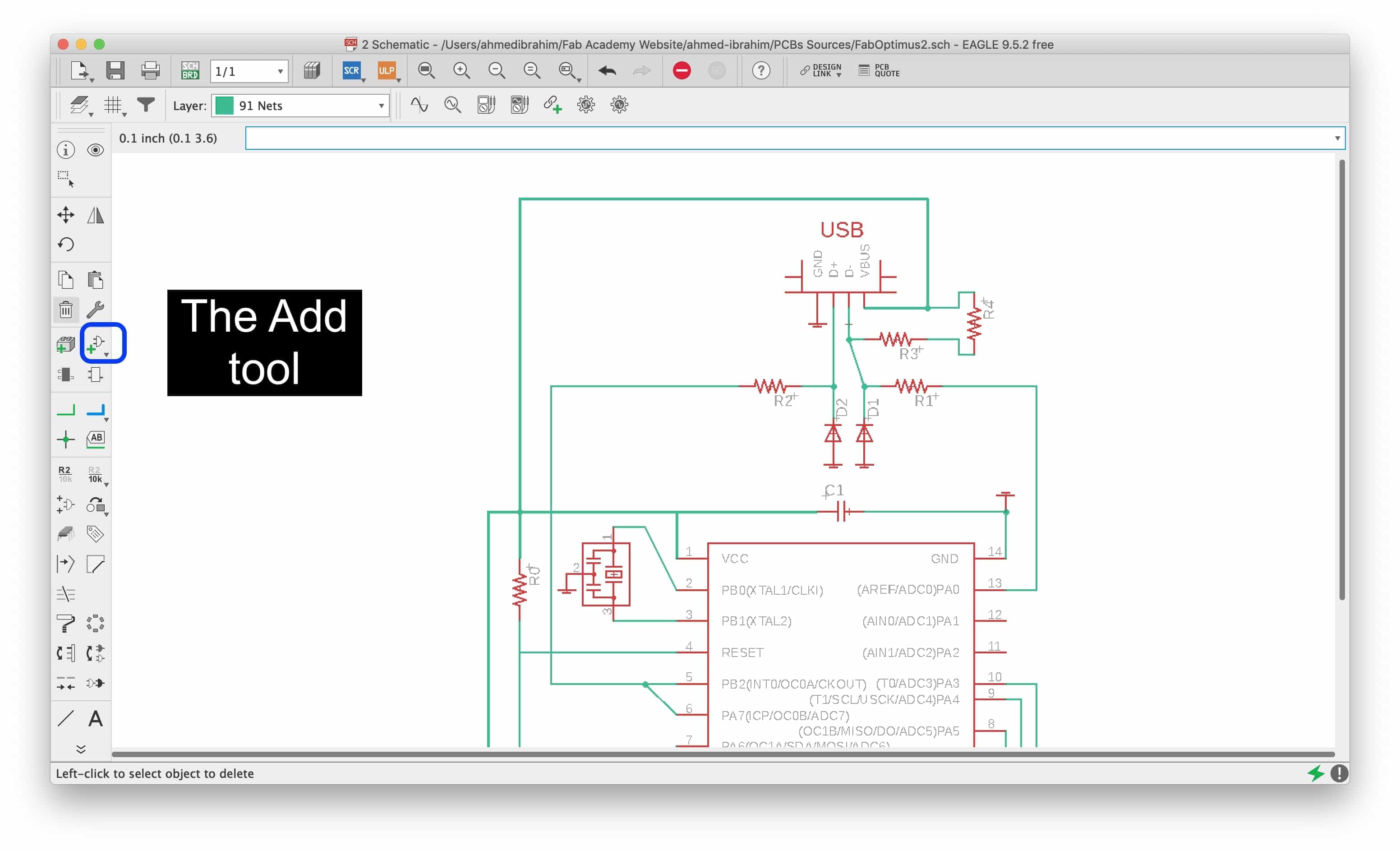
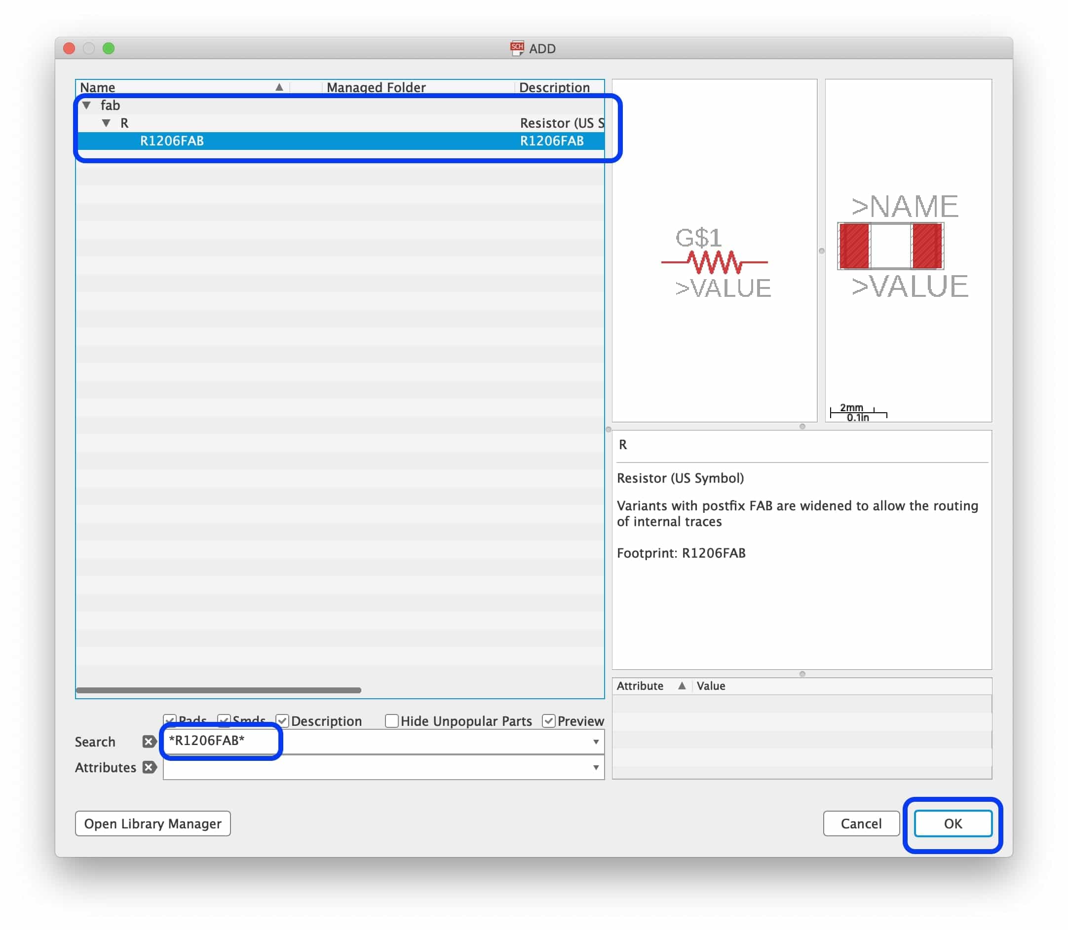
After inserting the LED, from the “Add tool” search for “*R1206FAB*” and insert it in your design. The resistor value doesn’t matter too much in your schematic as long as you are not making a simulation in EagleCAD, the most important thing is the component footprint. And later on when we start soldering the components we will choose the right resistor value to solder on that place.
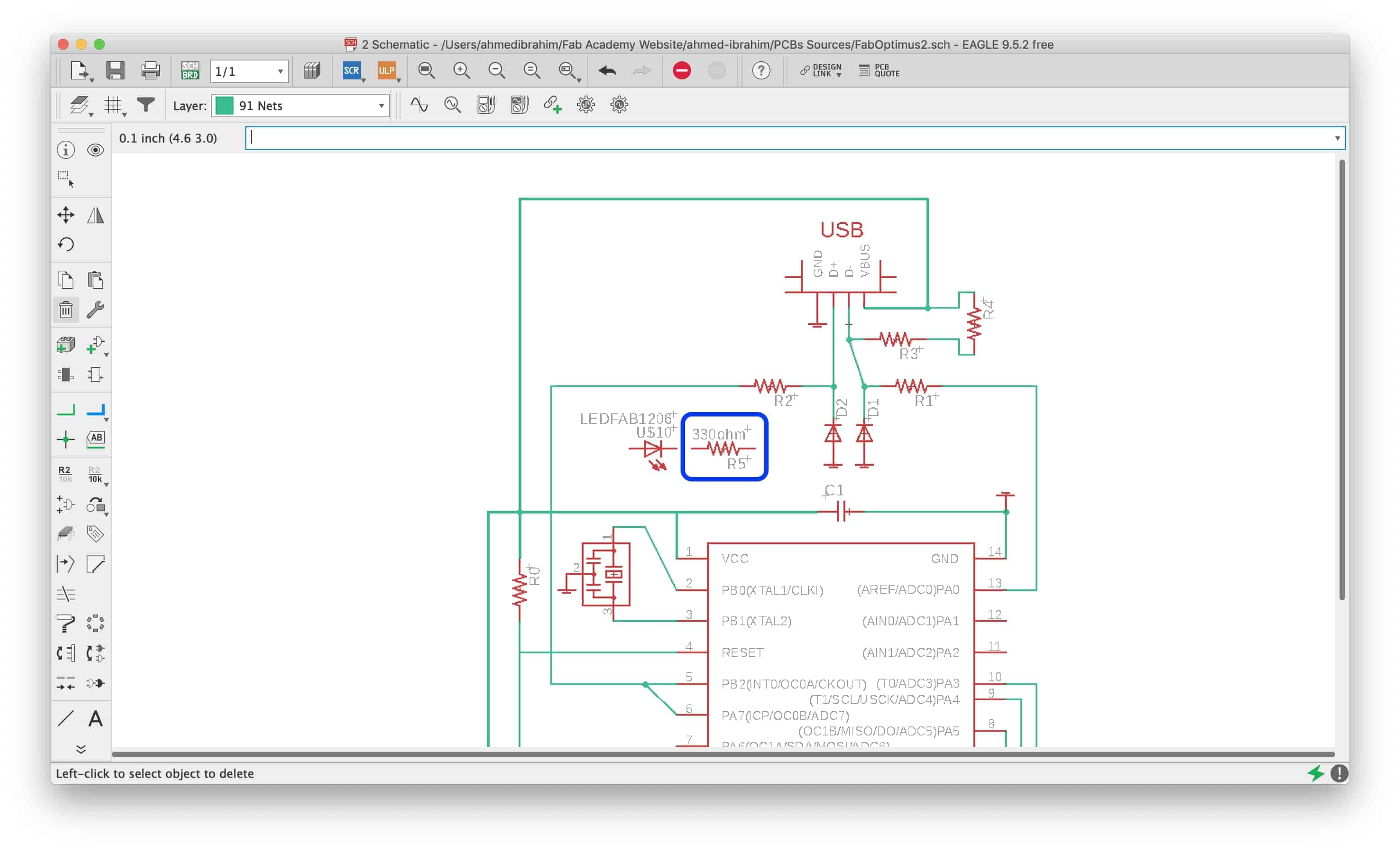
After adding the LED and the current limiting resistor, we will connect the positive terminal(Anode) of the LED to the USB positive (VBUS), the negative terminal(Cathode) of the LED to one of the resistor terminals, and the second resistor terminal to the GND.
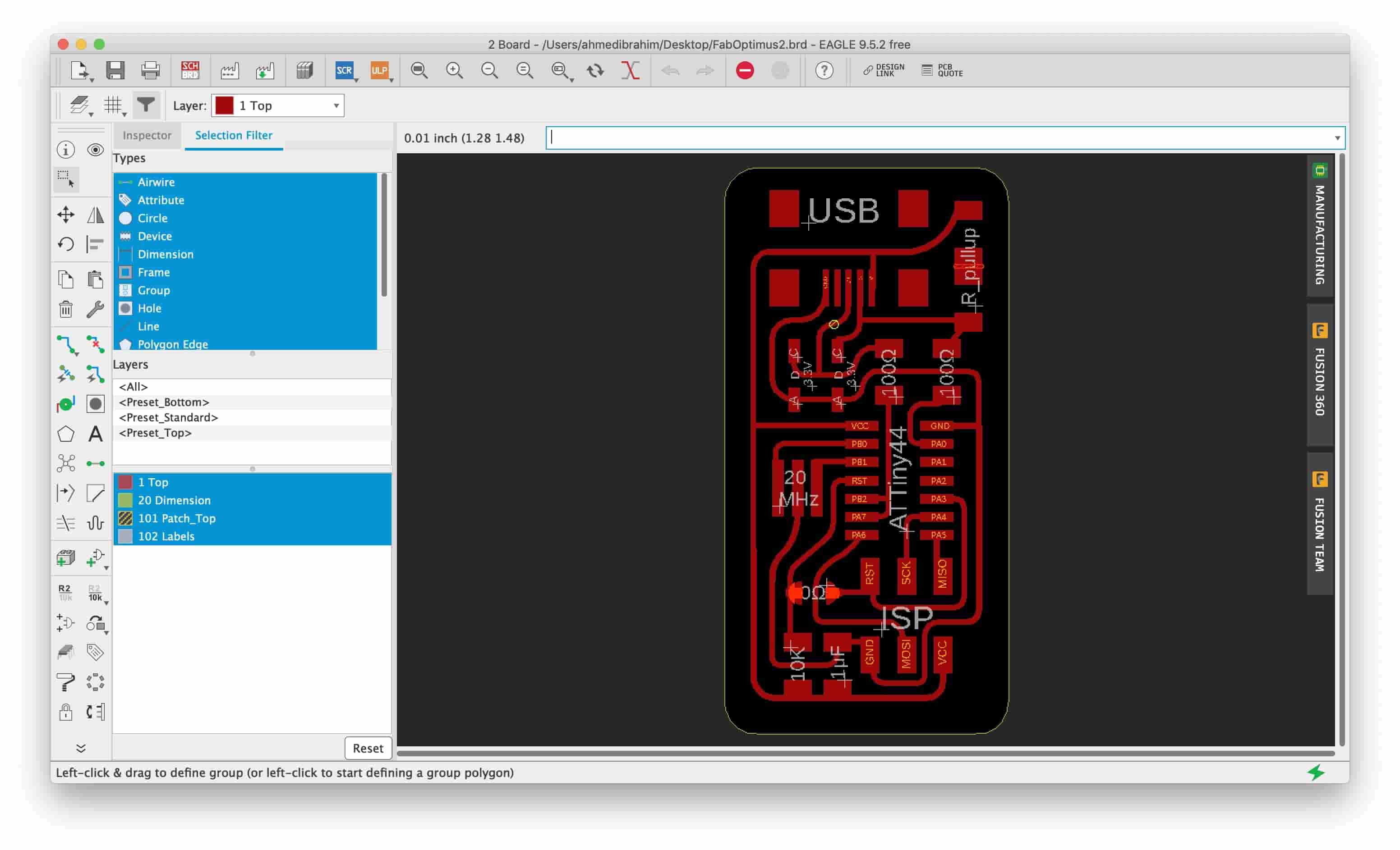
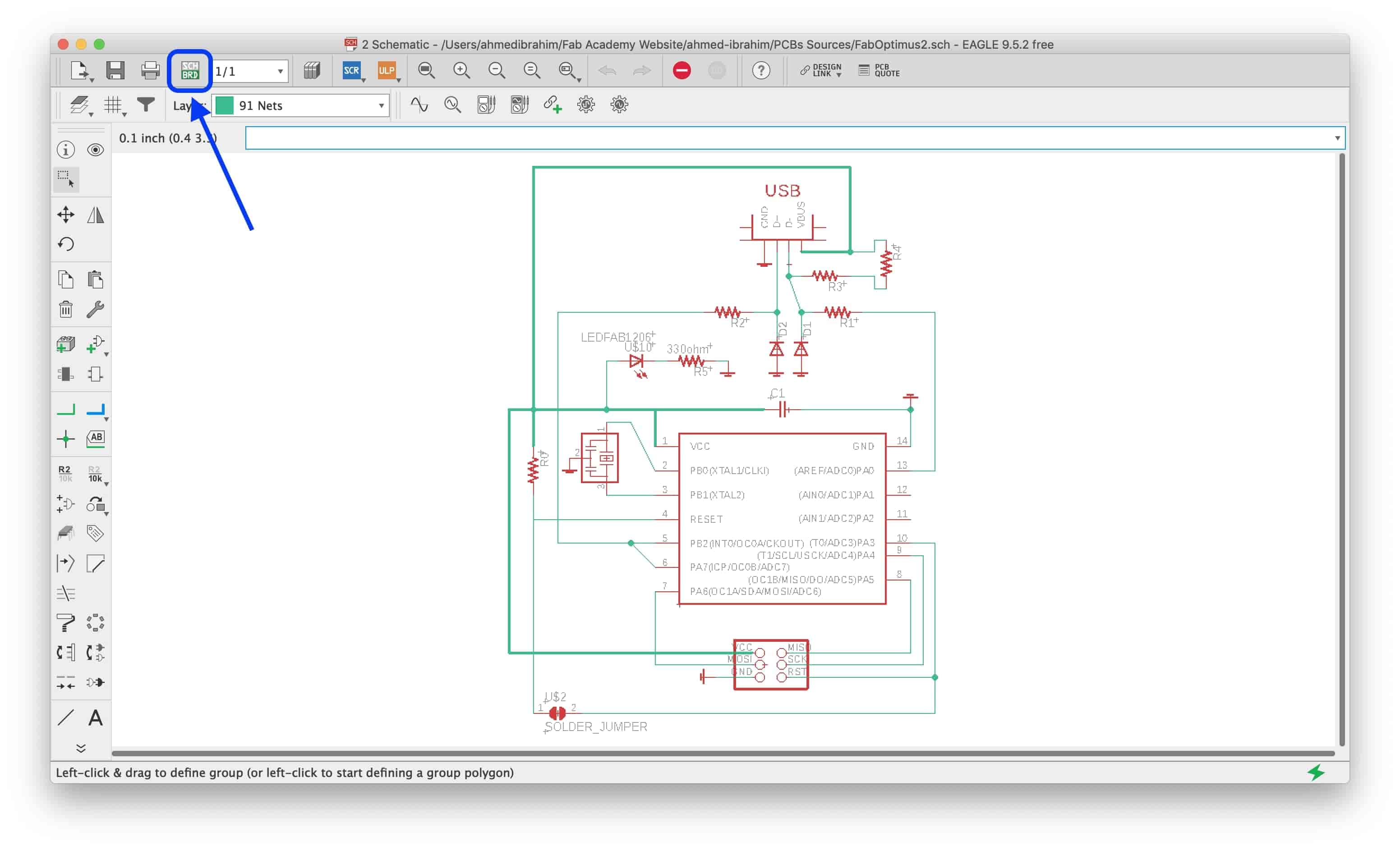
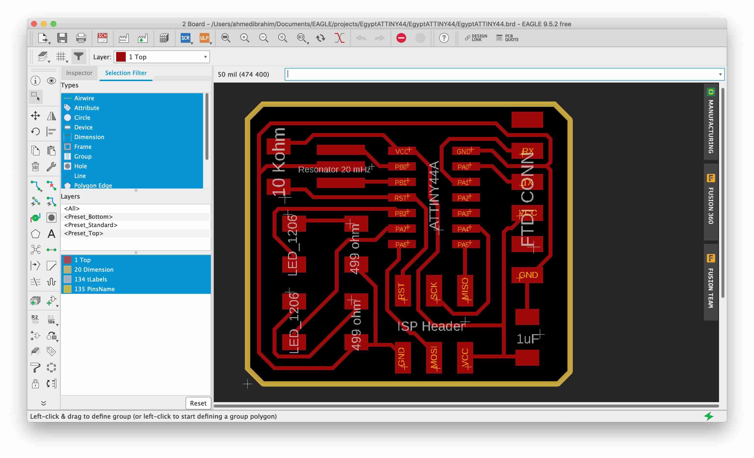
Now, we need to place the components on our board and finish the routing. Click on the “Generate/Switch to board” button and start rerouting the traces. I made a small edit on the PCB outline(profile) before rerouting the LED part.
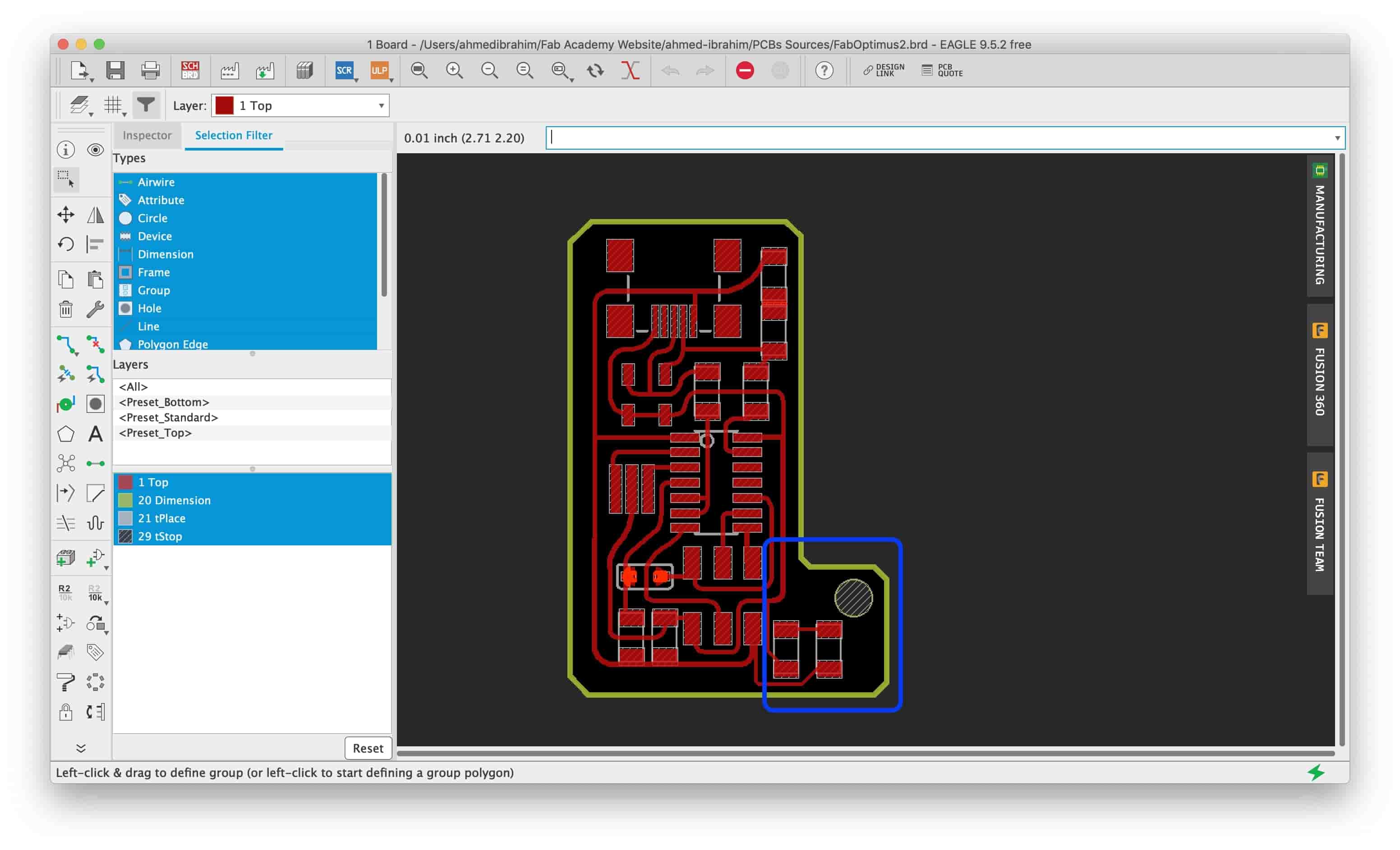
After that I Exported two PNG images, one for the Traces(copper) and the other one for the PCB Outline(profile). You can check week 7 assignment for how to export these PNG images for the MAC and Windows users.
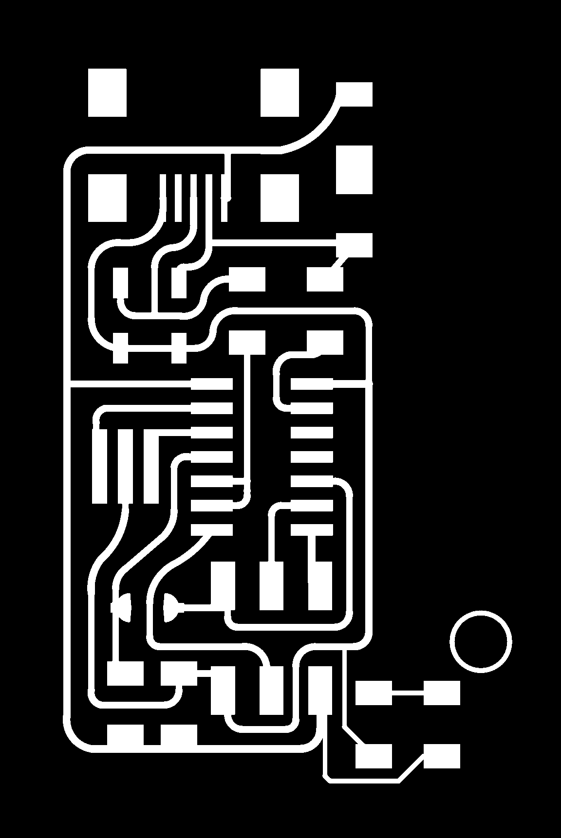
FabOptimus Edited PNG Files Download
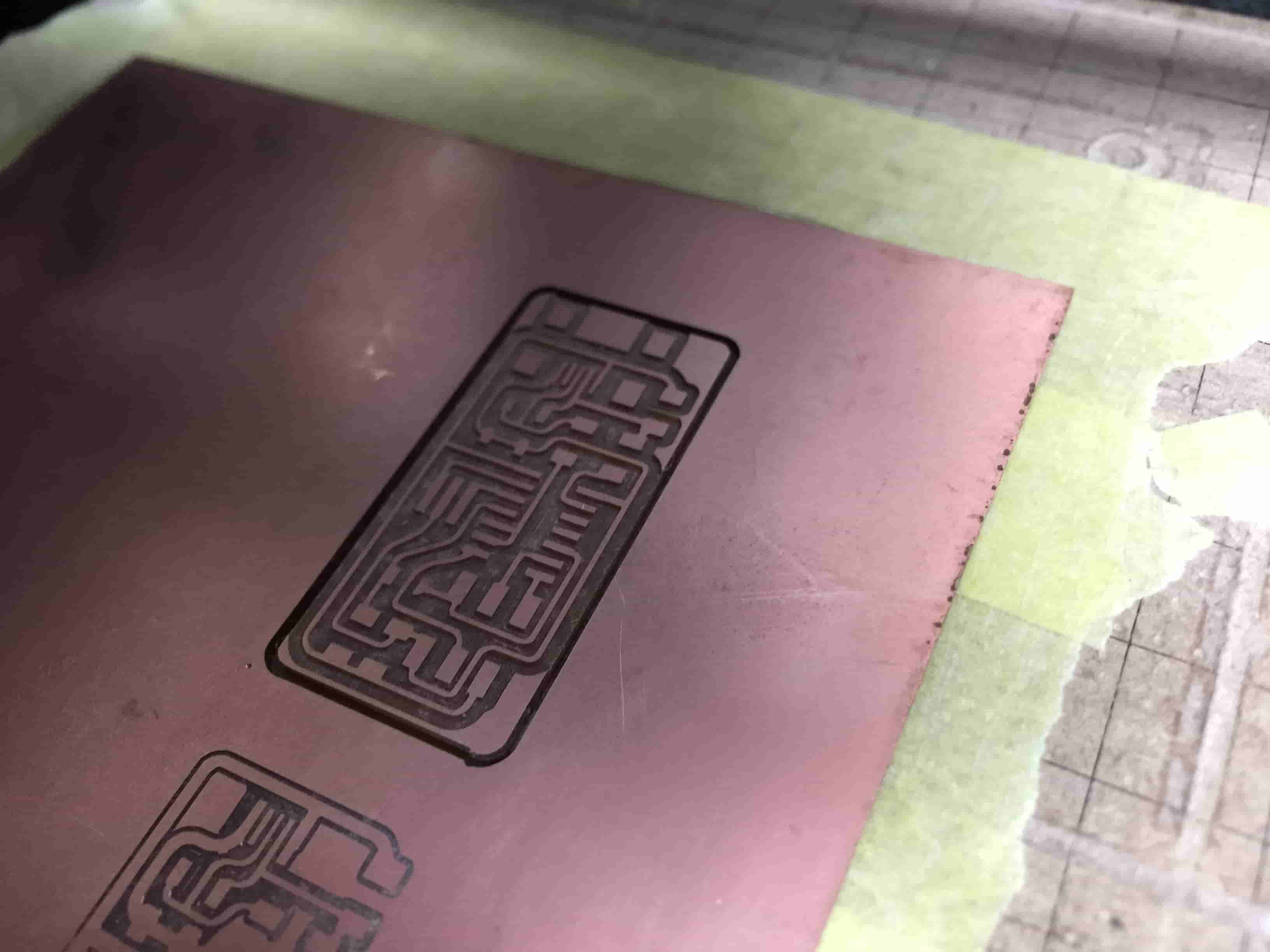
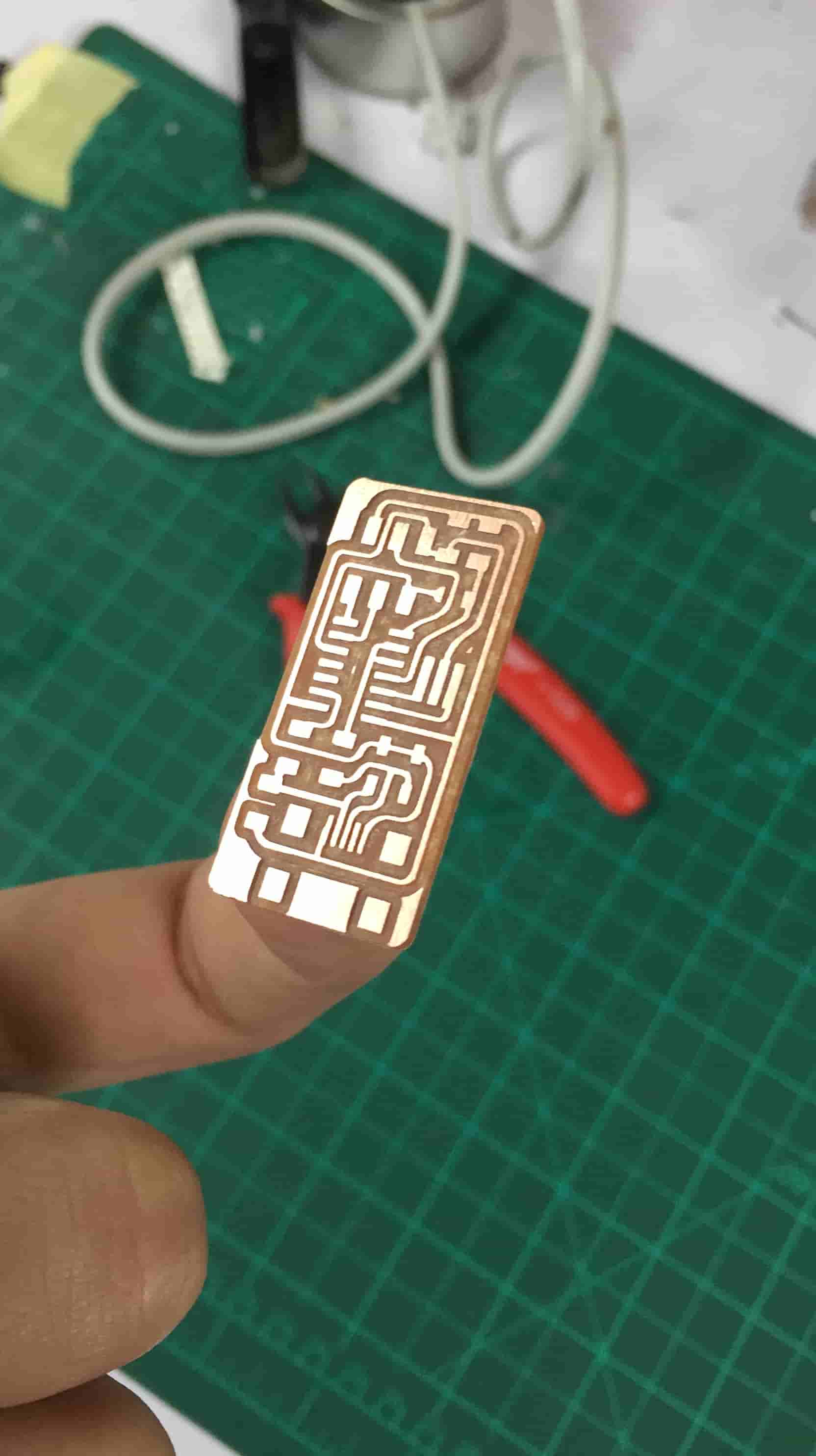
PCB Fabrication
We already discussed how to use the Fab modules CAM software and how to import the PNG images to it. We're gonna repeat the same procedure with the same concept that we explained in the group assignment part. After installing the PCB on the machine bed and installing the 1/64inch bit in the machine collet, Import the traces PNG image, set the Output Format to Rolland Mill, set the Process to PCB Traces(1/64inch), and the Machine to MDX-20 the one we use in Fab Lab Egypt.
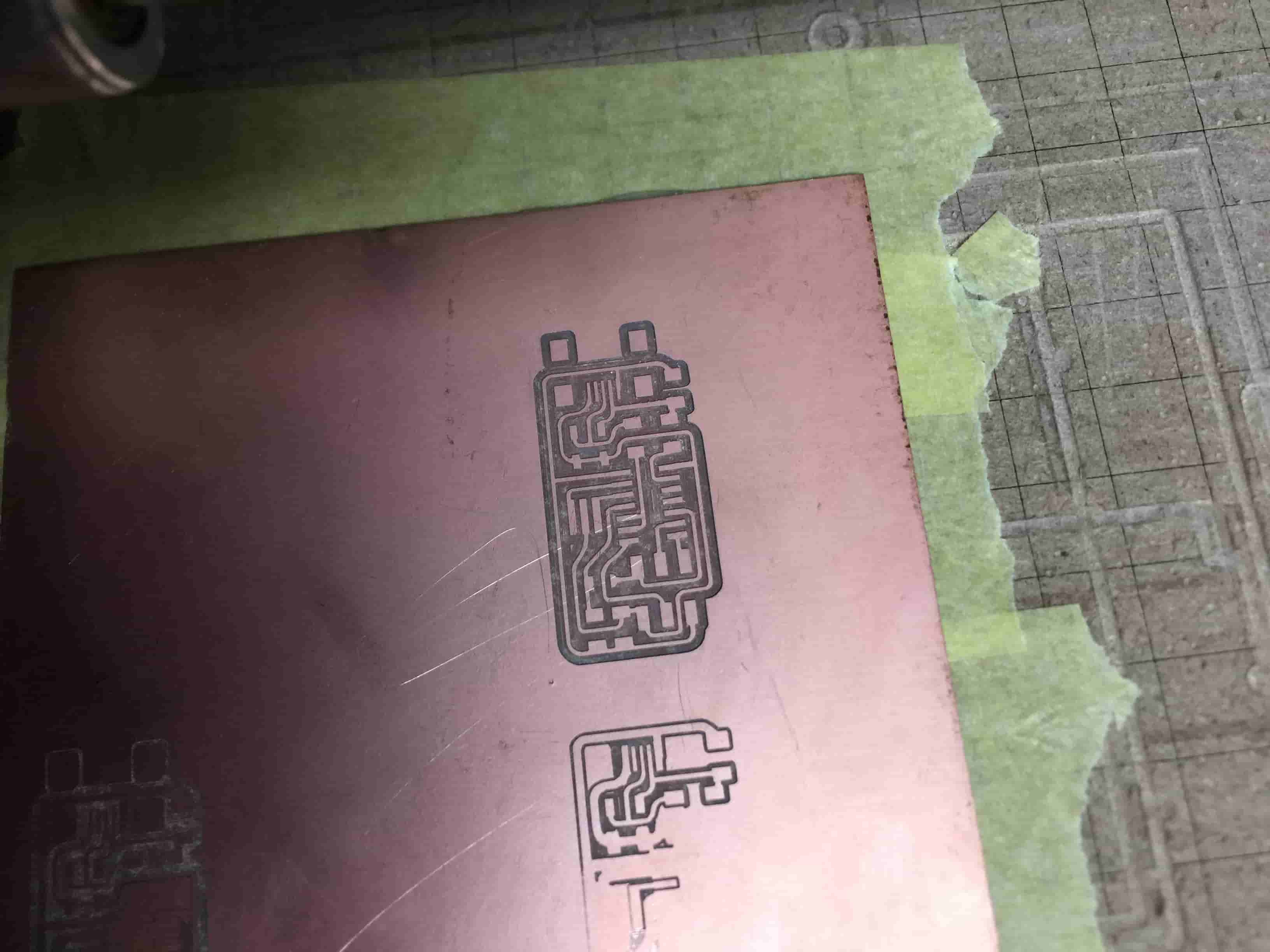
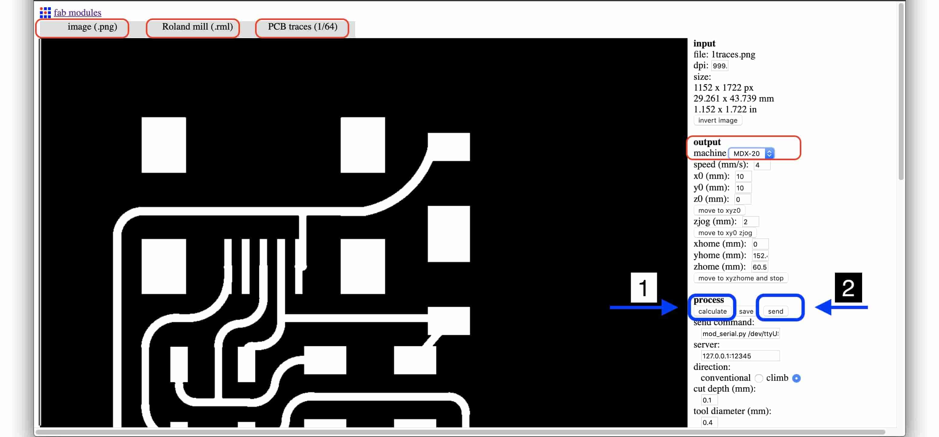
Now we need to calculate the toolpath of the machine, So, we will press on the “Calculate” button and double check the toolpath if there are any problems or something weird. If everything is good, just press “Send” and let the machine do it’s work.
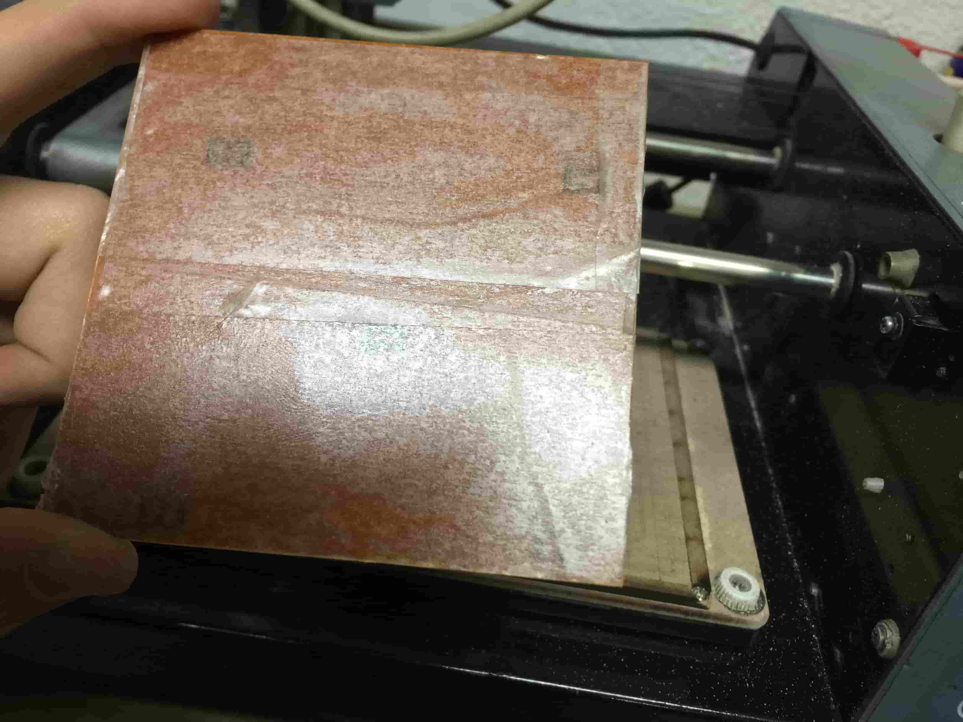
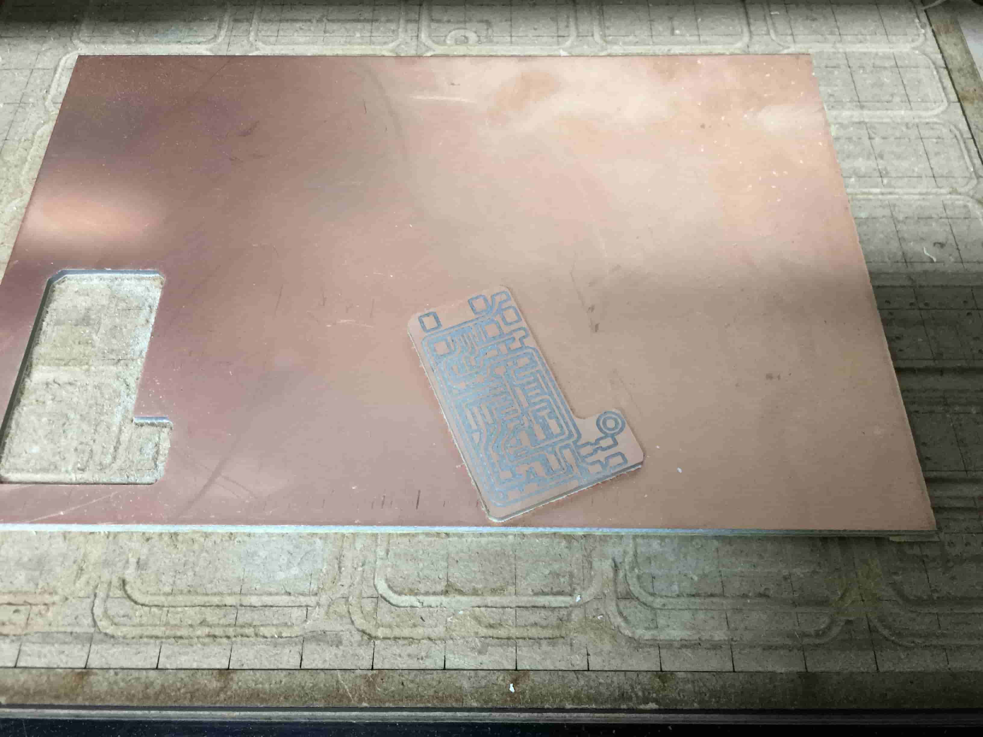
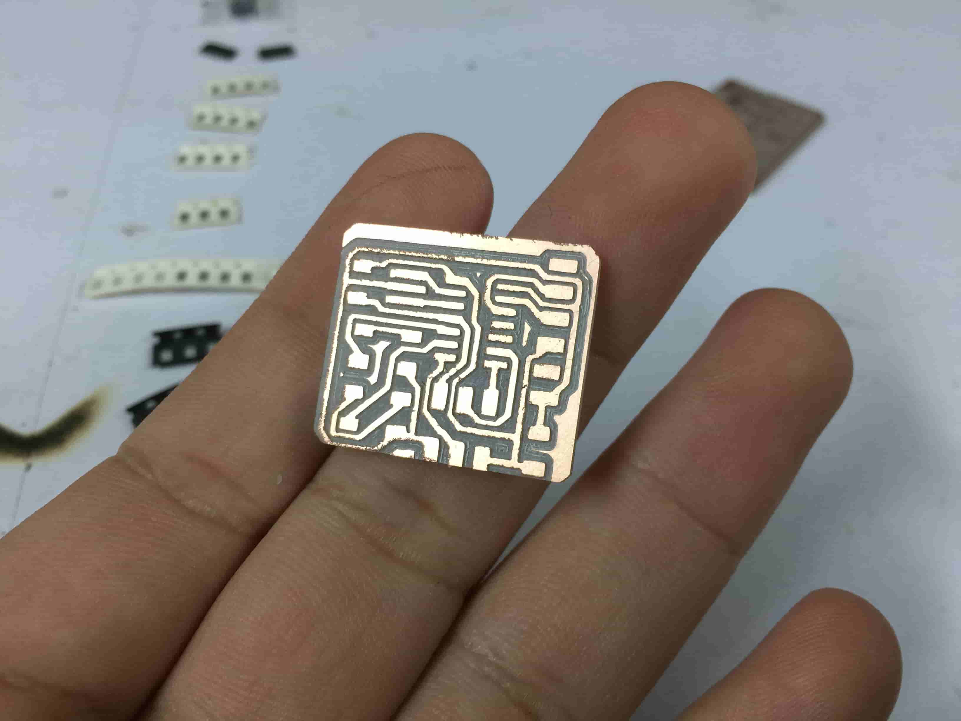
After getting the traces done, we need to change the 1/64inch bit that we installed before to the 1/32 endmill to cut the PCB profile(Outline). Then, we need to import the board profile PNG image, set the Output Format to rolland mill, then the Process to PCB Outline(1/32inch), and the Machine to MDX-20 the one we use in Fab Lab Egypt. Then click “Calculate” and if the toolpath is good, press “Send”.
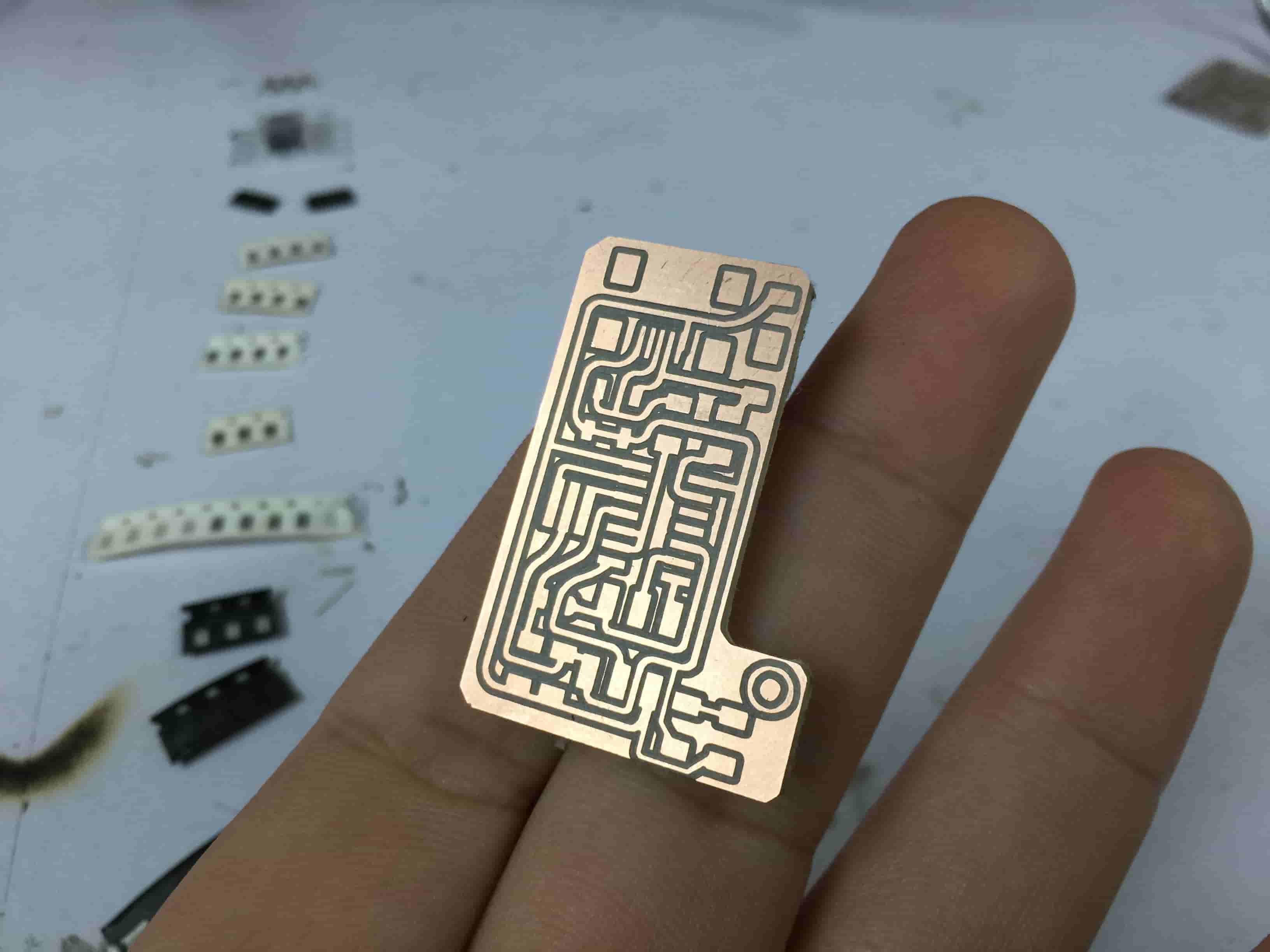
Now, board fabrication process should be done. The next step is to solder the components on the PCB.
PCB Soldering
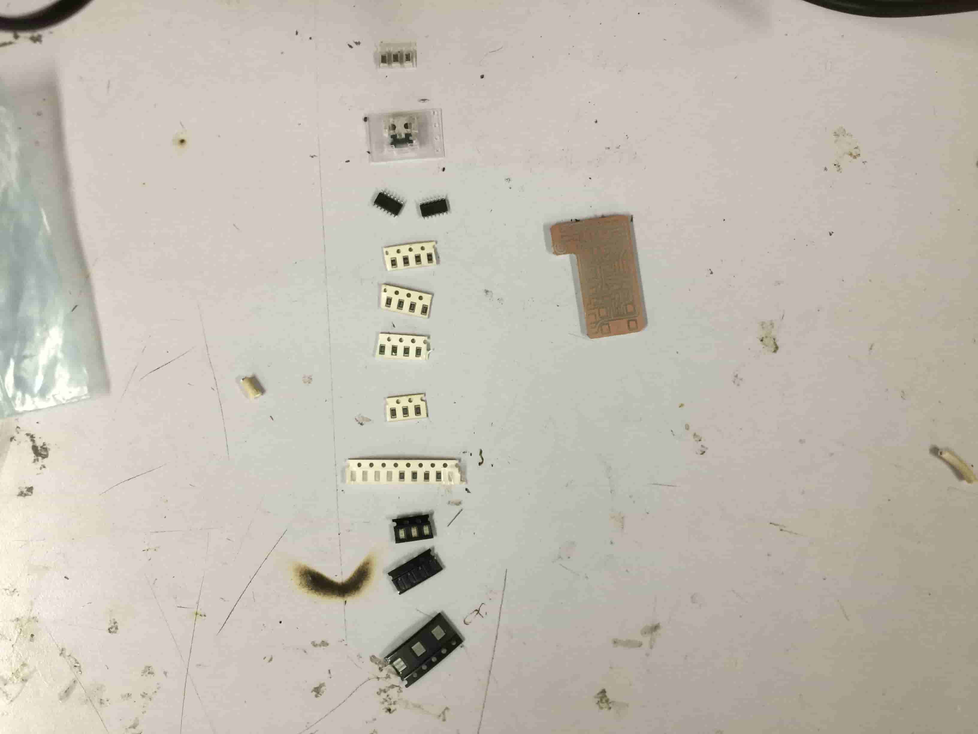
Before doing anything, we need to know what are the components that we need to use? So, here’s the BOM of all the components that we will need in order to finish this board.
The Used Electronic Hardware
| Part Number | Description | Quantity |
|---|---|---|
| ATTINY44A-SSU-ND | IC AVR MCU 4K 10MHZ 8SOIC- | 1 |
| XC1109CT-ND | CER RESONATOR 20.00MHZ SMD | 1 |
| SH2961CT-ND | CONN RECEPT MINI USB2.0 5POS | 1 |
| 609-5161-1-ND | 6 Positions Header Connector 0.100" SMD | 1 |
| 445-1423-1-ND | CAP CER 1UF 50V X7R 10% 1206- | 1 |
| 311-10.0KFRCT-ND | RES 10.0K OHM 1-4W 1% 1206 SMD | 1 |
| 311-1.00KFRCT-ND | RES 1.0K OHM 1-4W 1% 1206 SMD | 1 |
| 311-4.99FRCT-ND | RES 499 OHM 1-4W 1% 1206 SMD | 2 |
| 311-100FRCT-ND | RES 100 OHM 1-4W 1% 1206 SMD | 2 |
| DIODE ZENER 500MW 3.3V SOD123- | BZT52C3V3-FDICT-ND | 2 |
| 160-1889-1-ND | LED Blue CLEAR 1206 SMD- | 1 |
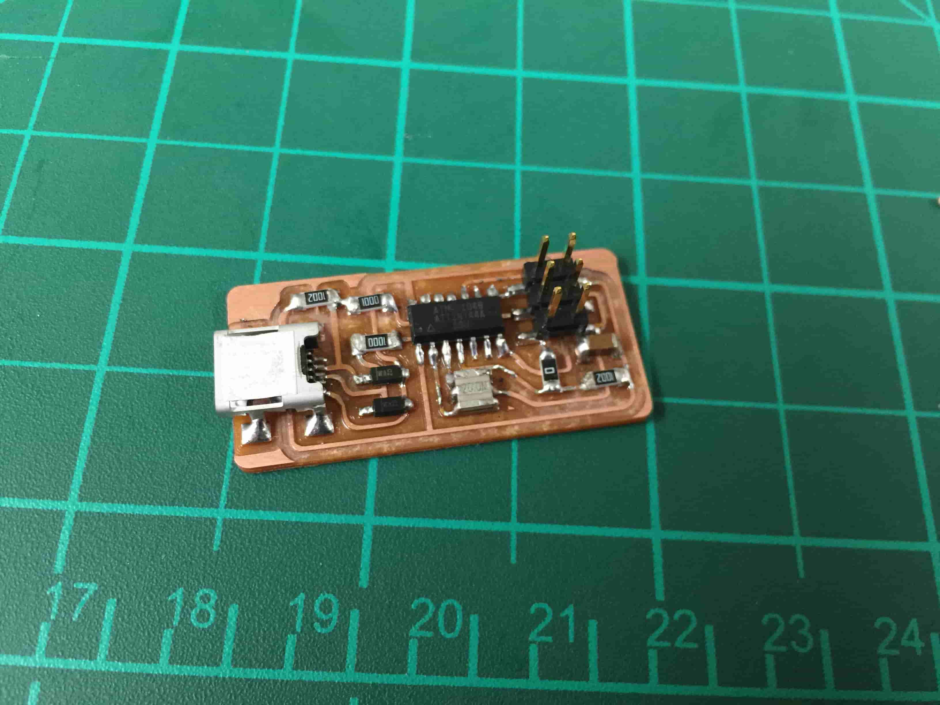
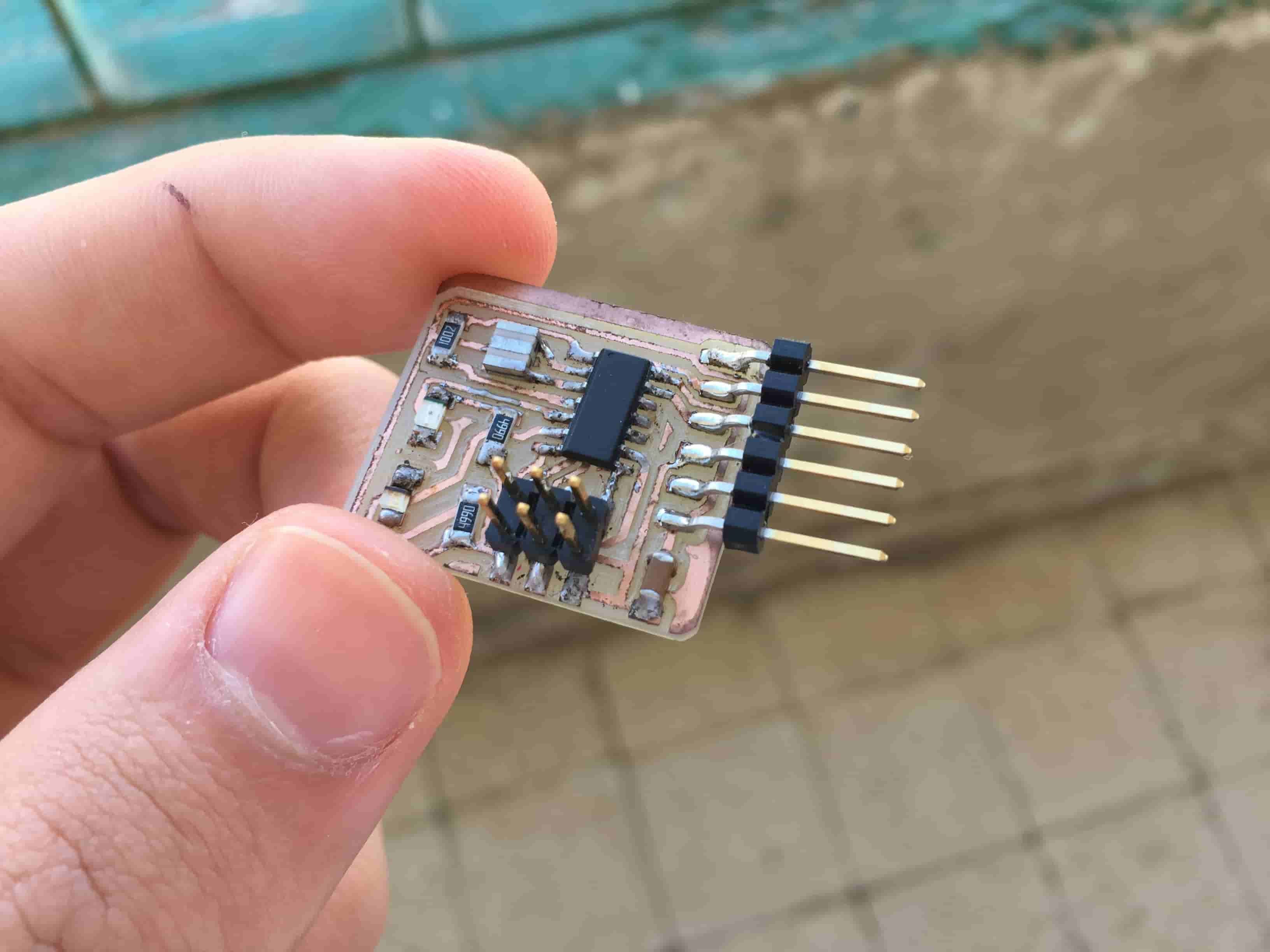
Knew the needed components and grabbed it, put them all on the work bench beside you and happy soldering. I started soldering from low to high. Means, soldering the small components first and ending by the bigger ones.
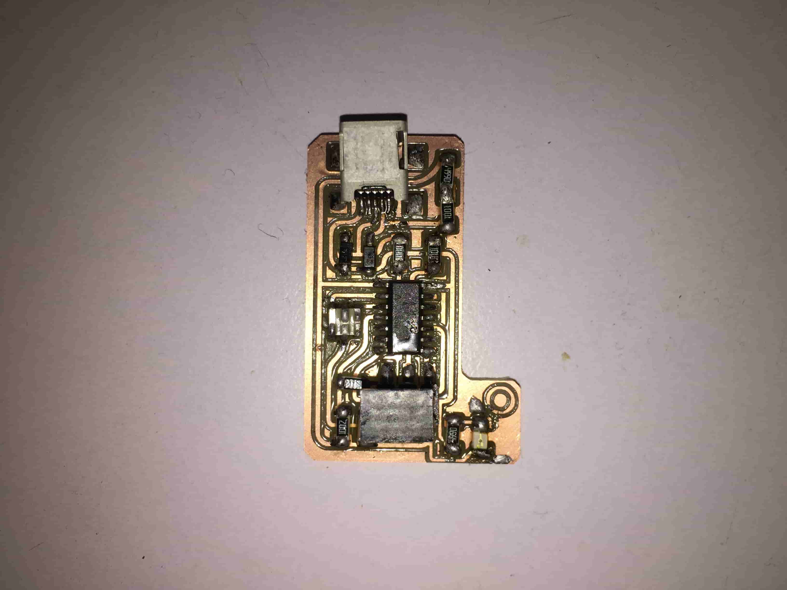
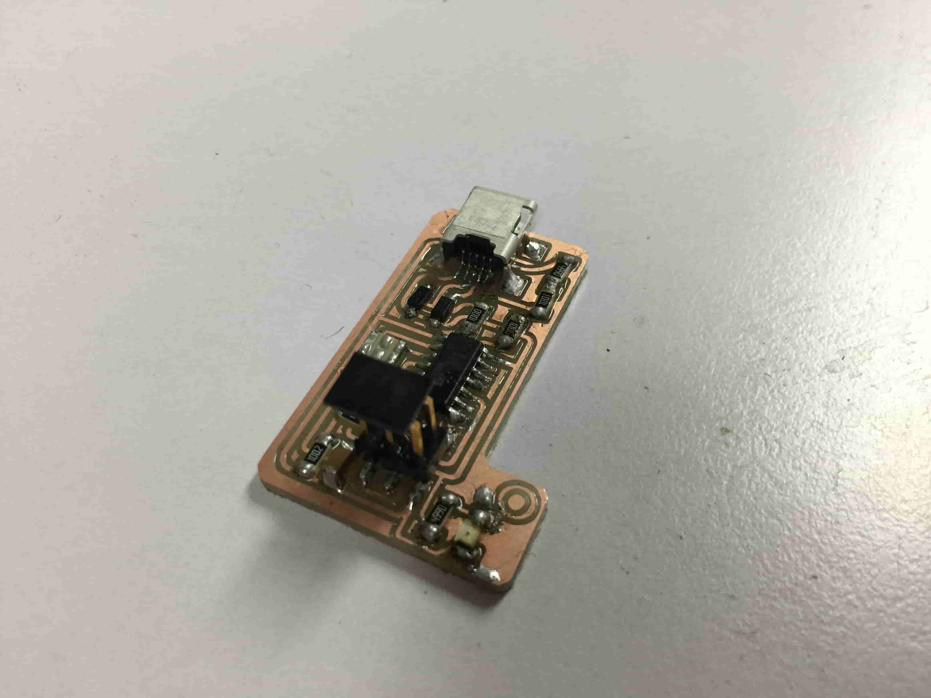
The most hard part is soldering the USB, the USB terminals is very very small and close to each other. Firstly, I tried to solder it using the soldering iron and solder. But, It failed. Then I tried to solder it using the solder paste and hot air and that went great.
FAB ISP Programming
At first, I tried to burn the firmware on the board using ATmel-ICE and I modified the MakeFile to meet the hardware that I use but it failed. I don’t know why! I thought about using another programmer. After doing some online search, I found that we can use the Arduino UNO board as a programmer. I read this awesome tutorial, it was amazing and very well explained. Since I already have an Arduino board, I said let’s give it a try.
First things first, to use the Arduino UNO board as a programmer we need to upload a piece of code named “ArduinoISP” we can find it in the File -> Examples -> ArduinoISP -> ArduinoISP. Before uploading the code example we need to edit the value in line no. 263 from 40 to 20. Then Upload the Code.

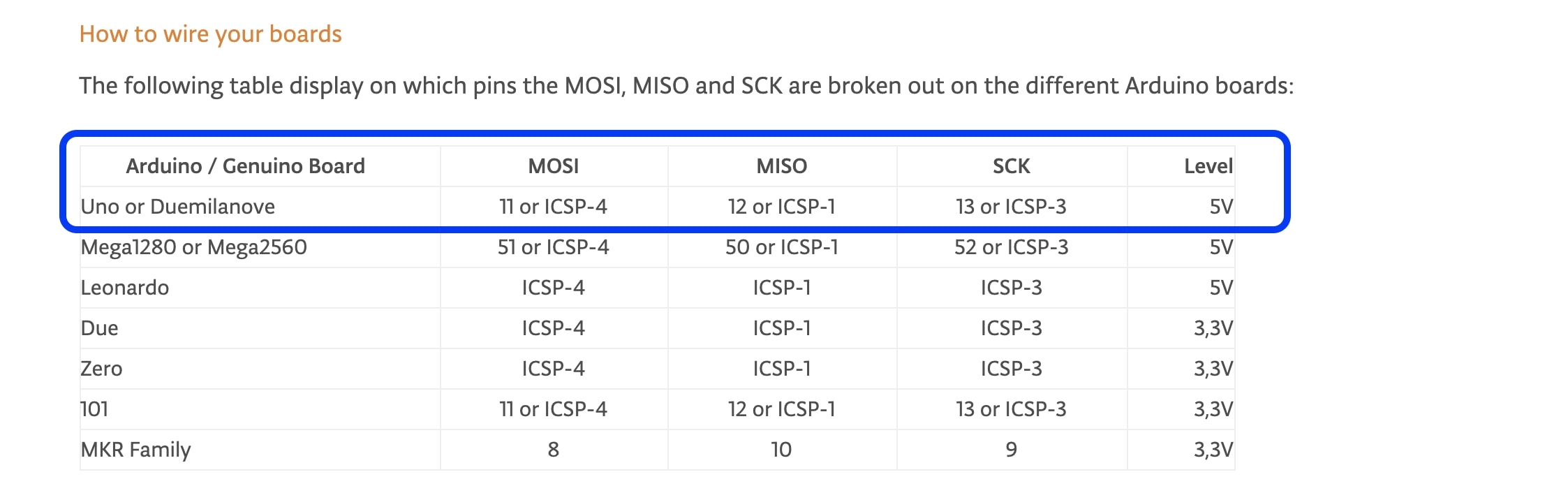
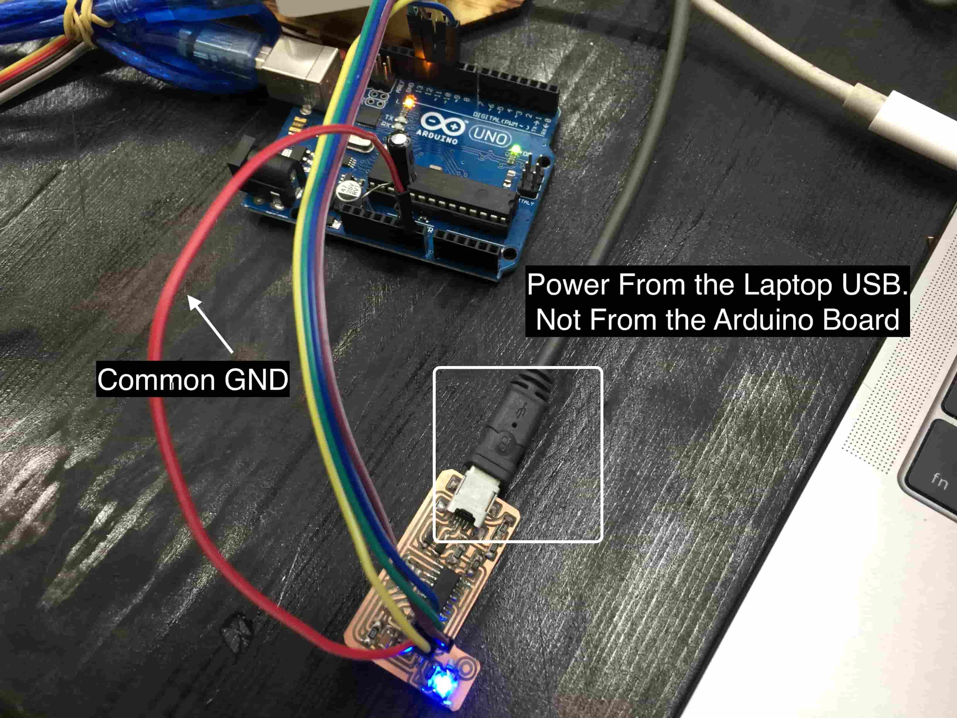
I brought my Arduino Uno and connected it to my ISP board(Target) according to this wiring diagram.
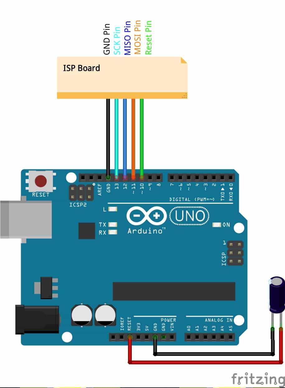
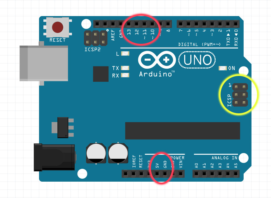
- D10(Arduino) --> Reset (Target)
- D11(Arduino) --> MOSI (Target)
- D12(Arduino) --> MISO (Target)
- D13(Arduino) --> SCK (Target)
- GND(Arduino) --> GND (Target)
As you notice, we are not providing power to our target board directly from the Arduino board. We are providing power to the target board by connecting it separately to the laptop through the USB port. And don’t forget to make a common GND between the two boards by connecting the GND of the target board to the GND of the Arduino UNO.
There are two ways we can connect out Arduino UNO(Programmer) to our target,The first one, through the built-in ICSP header. Or, through the digital pins. Both of them will work just fine. I chose to use the SPI protocol pins through the digital pins.
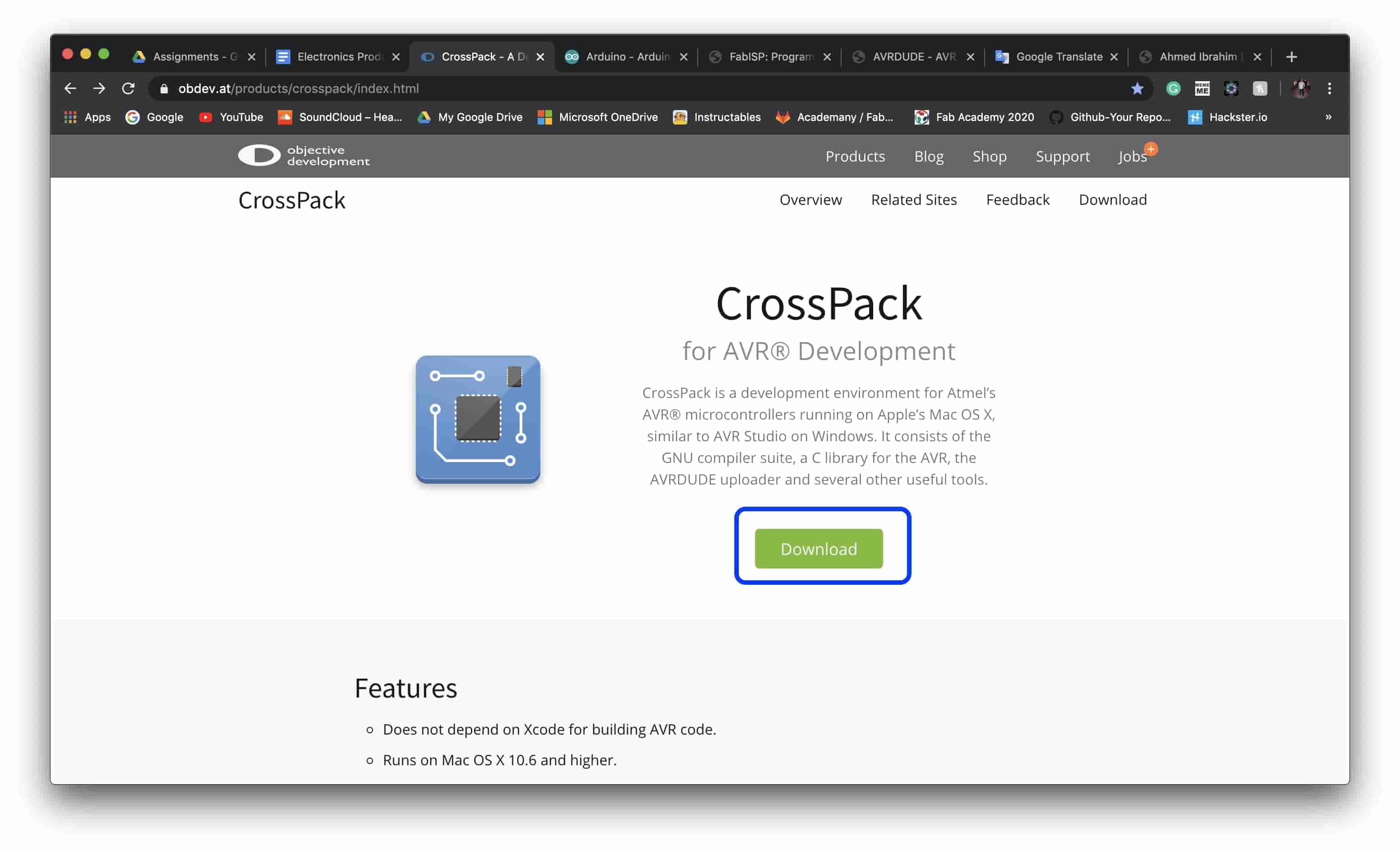
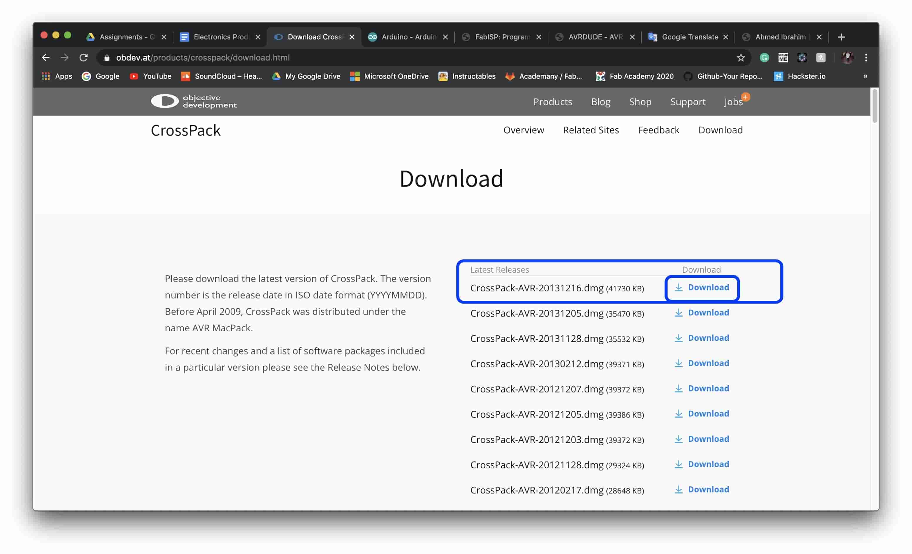
Since I’m using a MAC, we're gonna need to install AVR CrossPack. “CrossPack is a development environment for Atmel’s AVR® microcontrollers running on Apple’s Mac OS X, similar to AVR Studio on Windows. It consists of the GNU compiler suite, a C library for the AVR, the AVRDUDE uploader and several other useful tools.” After heading to AVR CrossPack website, click the “Download” button and install the .dmg file. That’s it!
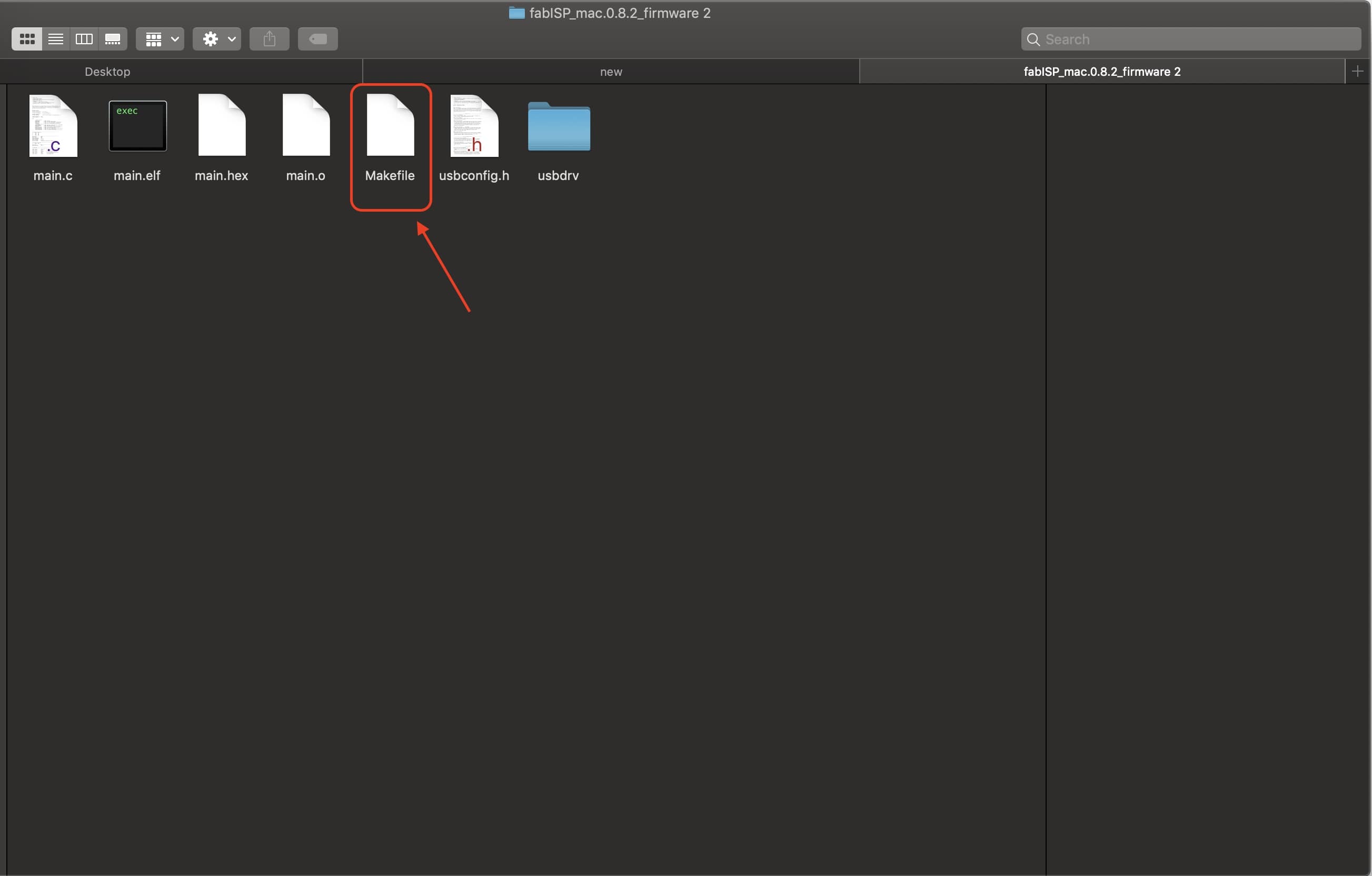
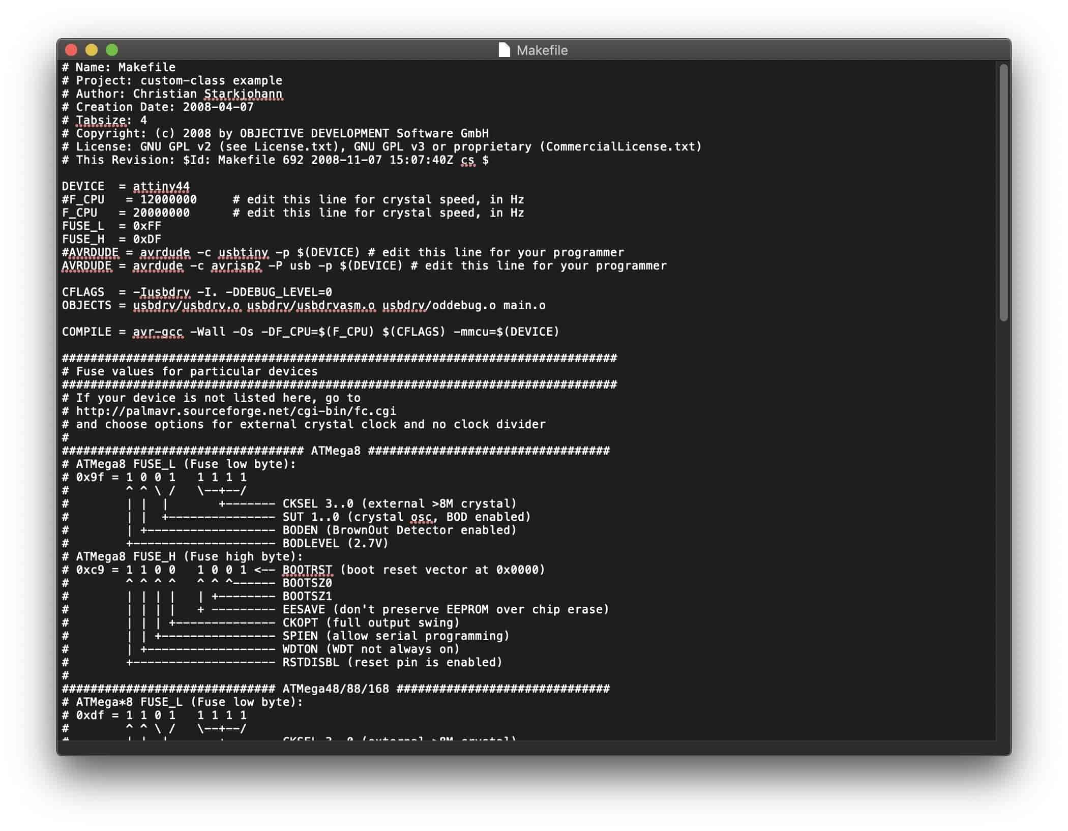
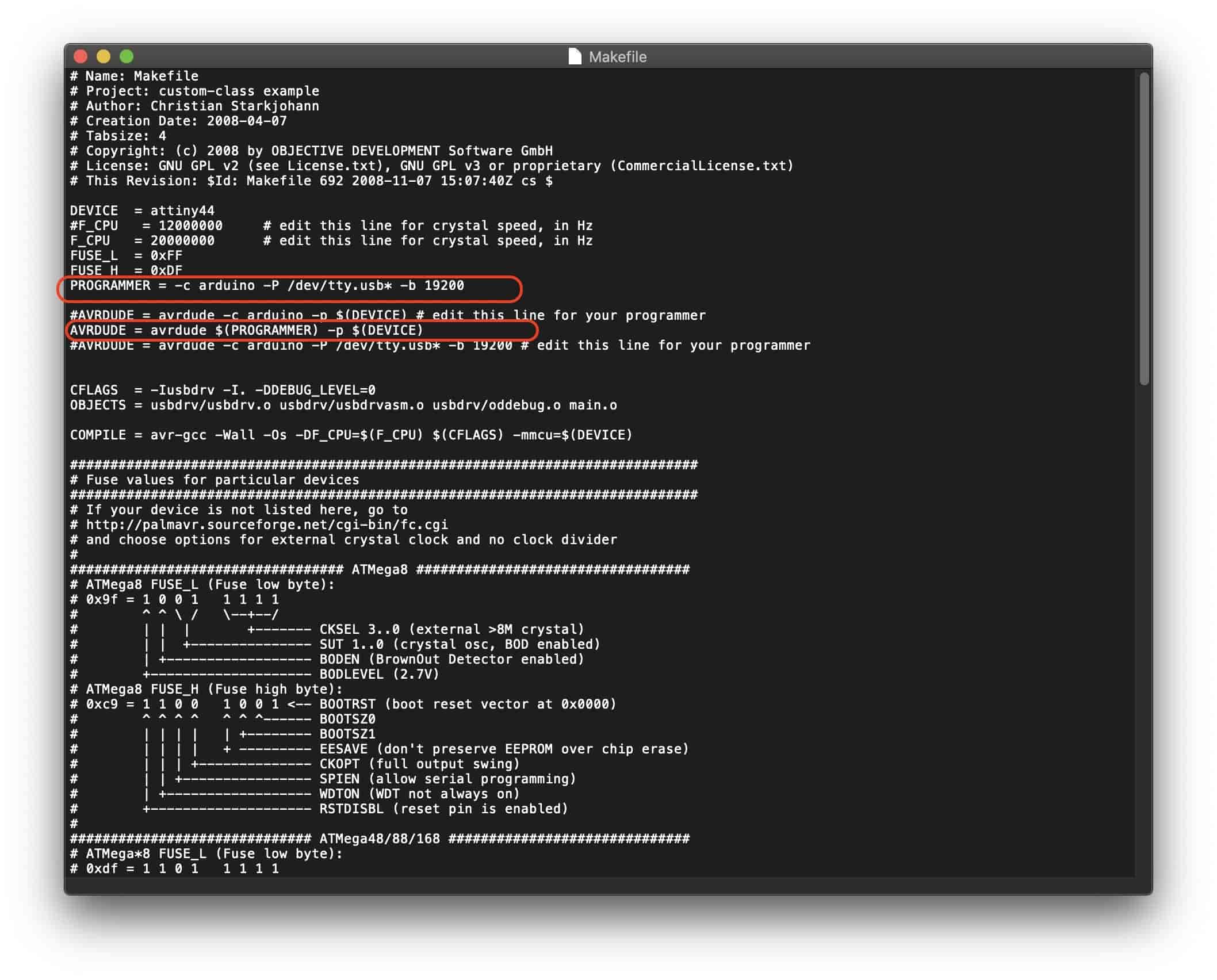
Then we need to download the FabISP firmware from this link. The Makefile which is inside the firmware folder is ready to use with the avrisp2 or the usbtiny, if you will use a different programmer from these two options it will not work. So, I made some tweaks to that Makefile to make it compatible with the Arduino Uno that I use as a programmer.
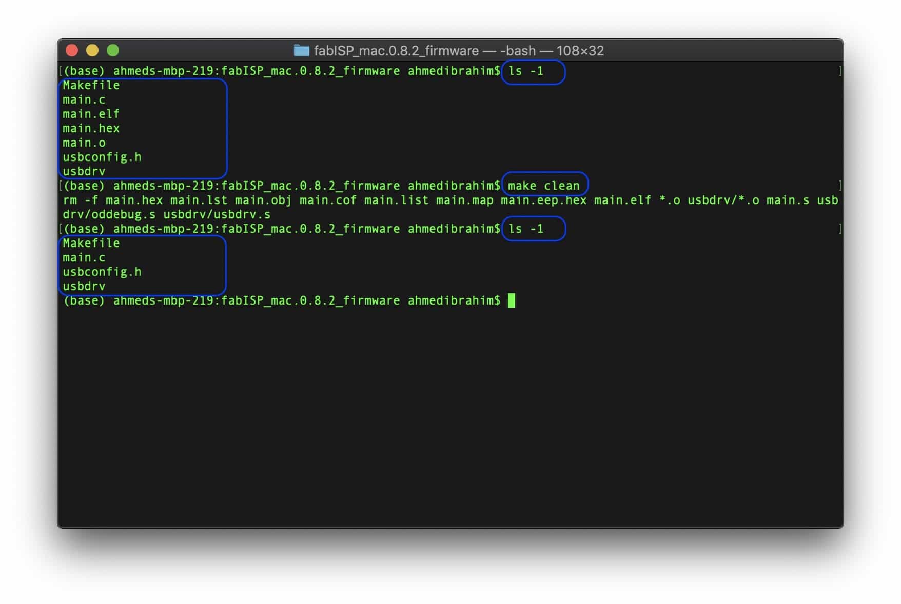
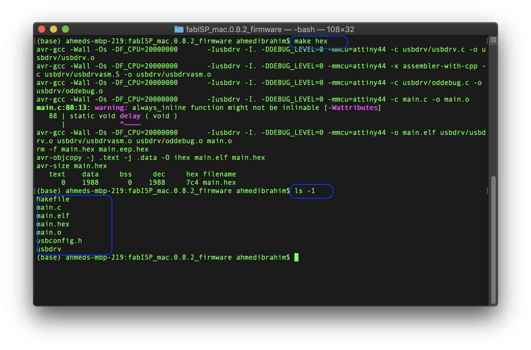
After updating the MakeFile, we will open the terminal and navigate to the firmware folder. Then, clean any previous compiled files by writing make clean. Then we need to generate a new .hex that meets our new MakeFile. We will use the make hex command.
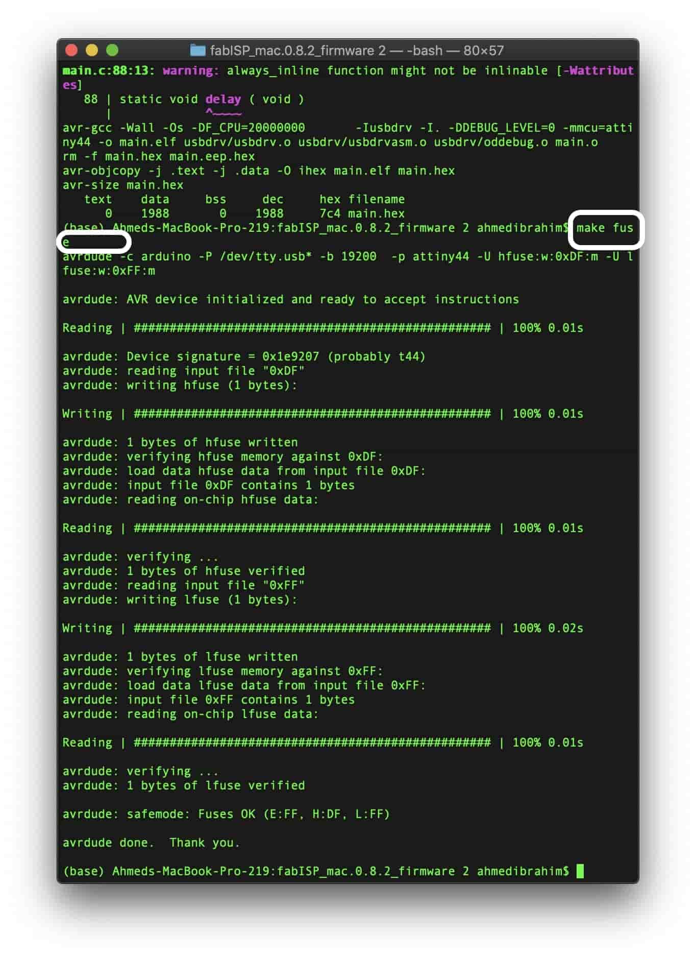
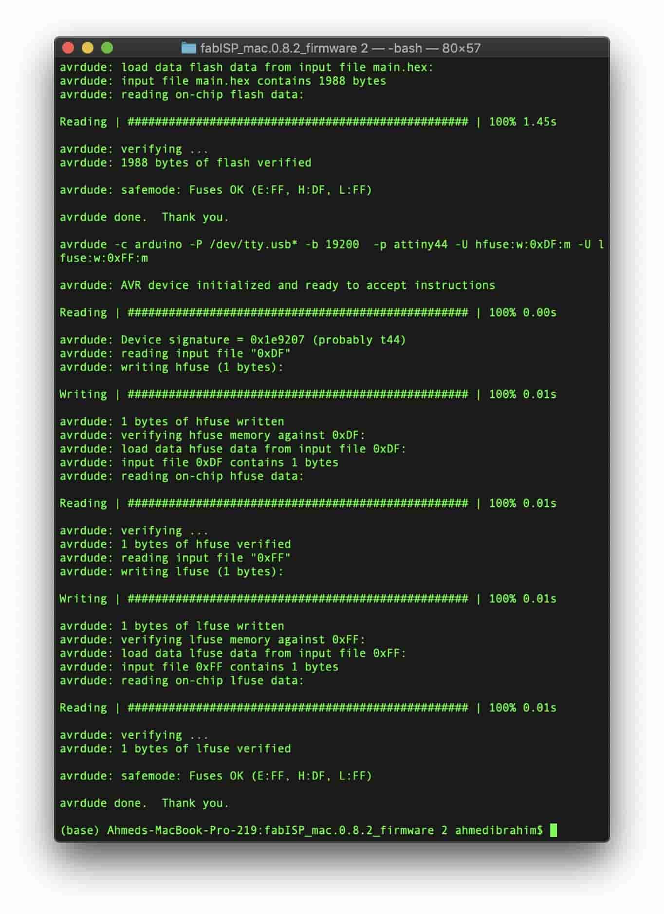
Then make fuse to set the fuses so the board will use the external clock. You should see a response like that. Lastly, use this command make program to burn our firmware to the board to work as an ISP.
Firmware MakeFile Download (ArduinoISP Ready)
FabISP Testing
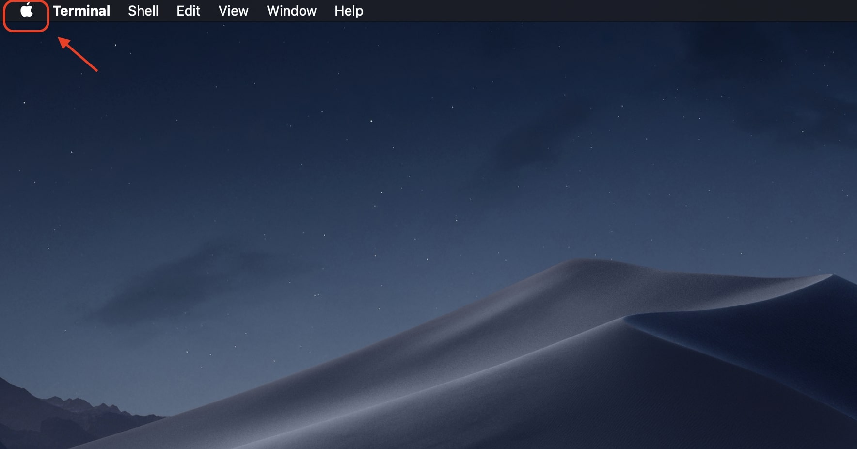
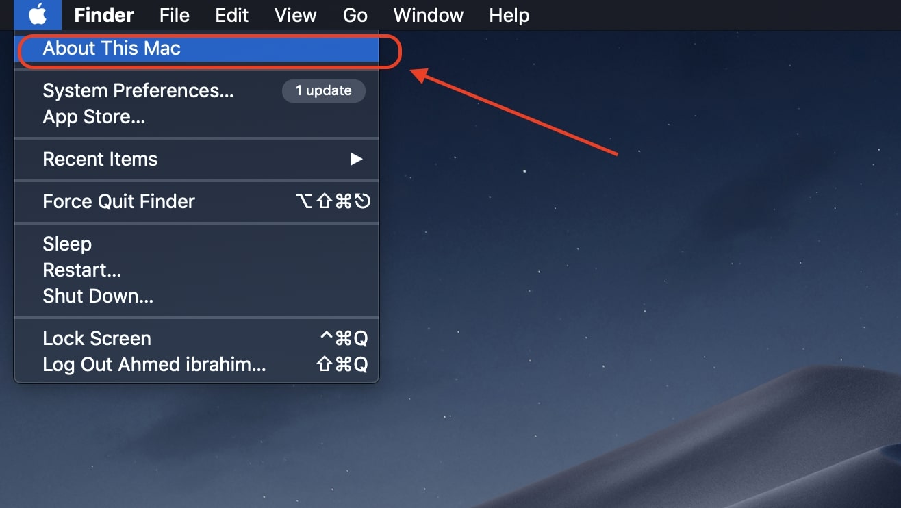
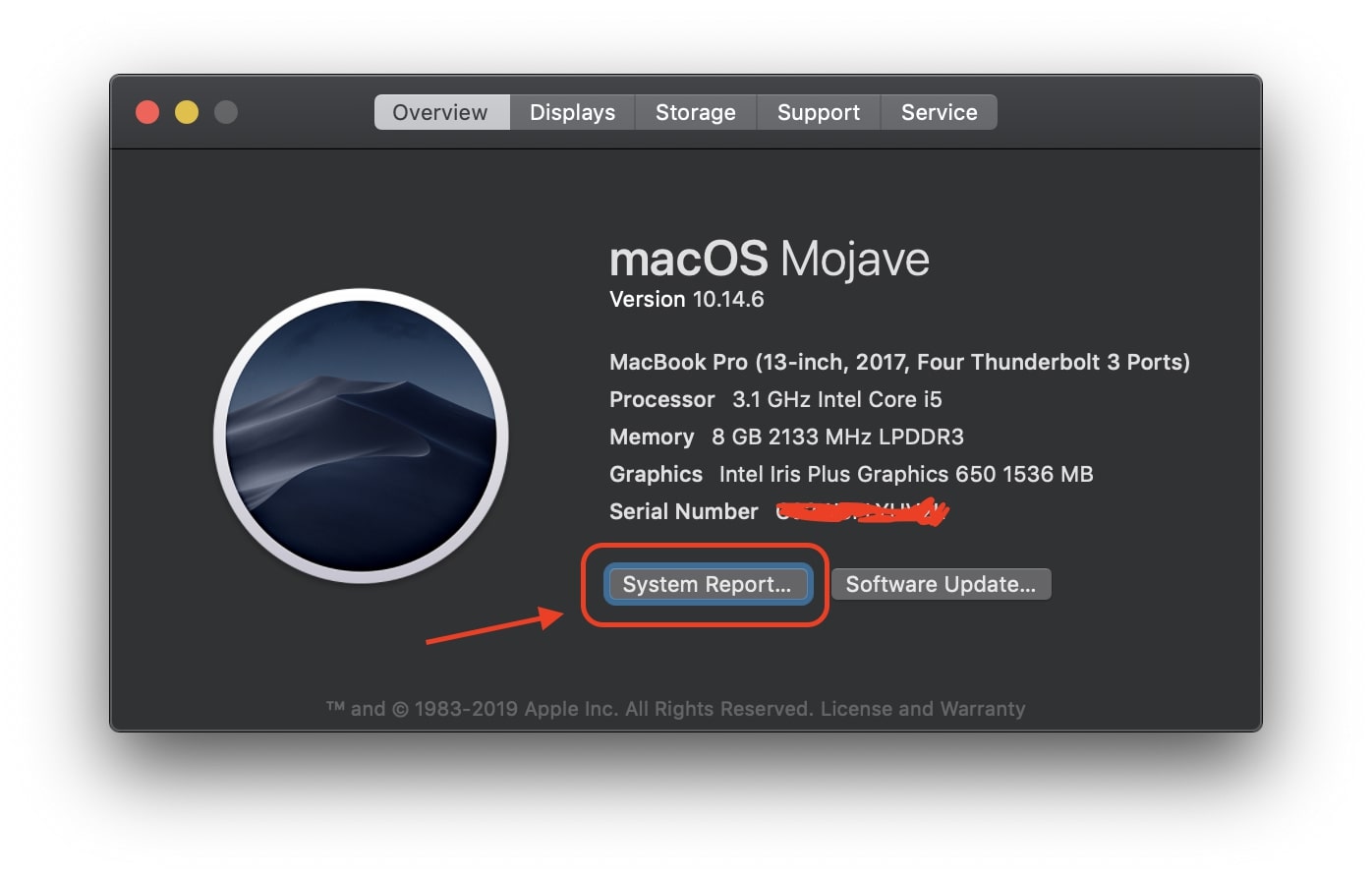
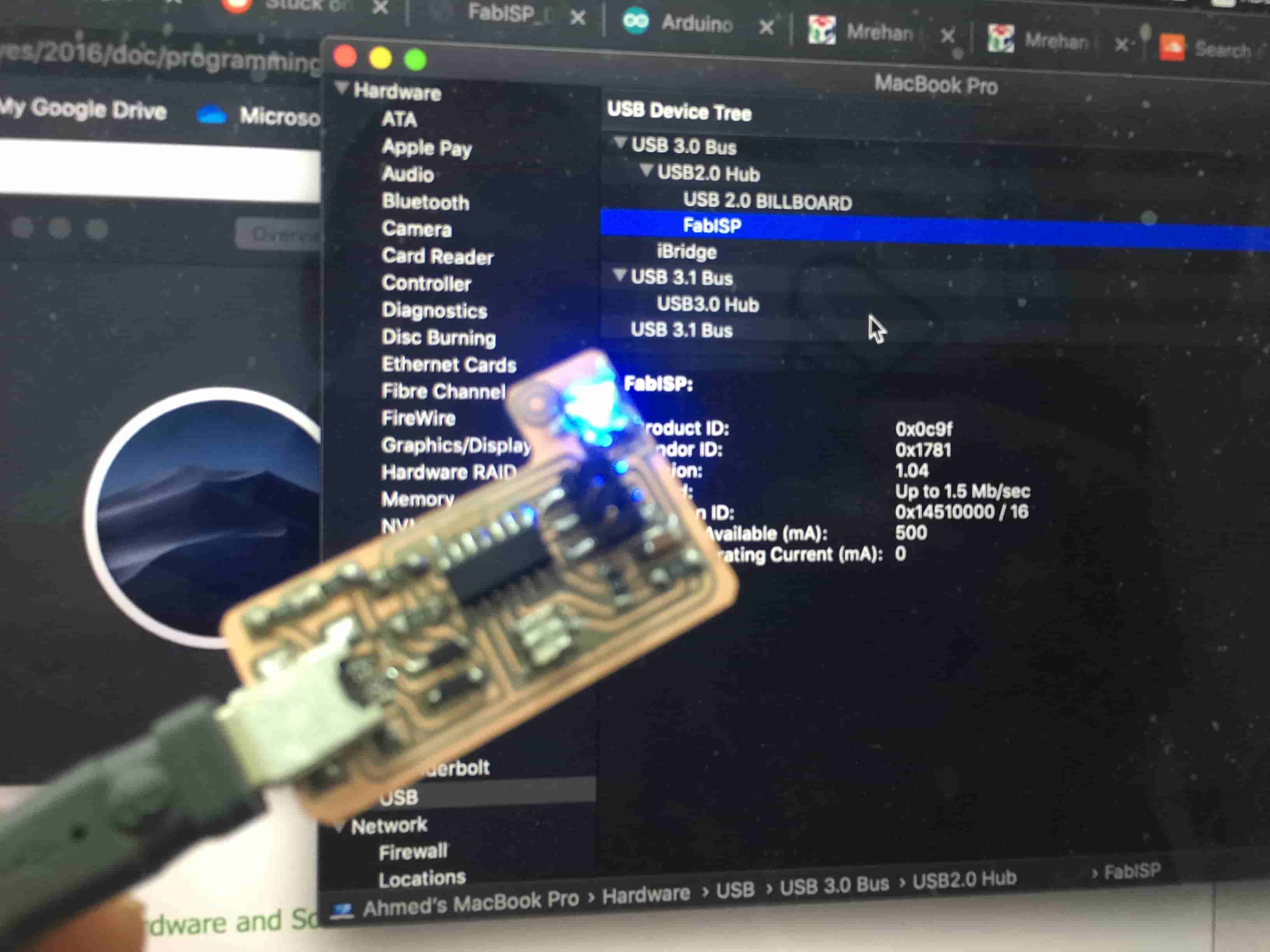
After finishing the previous steps, your computer should now recognize the board as an ISP. Since i’m using a MAC machine, click on the Apple logo, then click in “About This MAC”, then “System Report”.
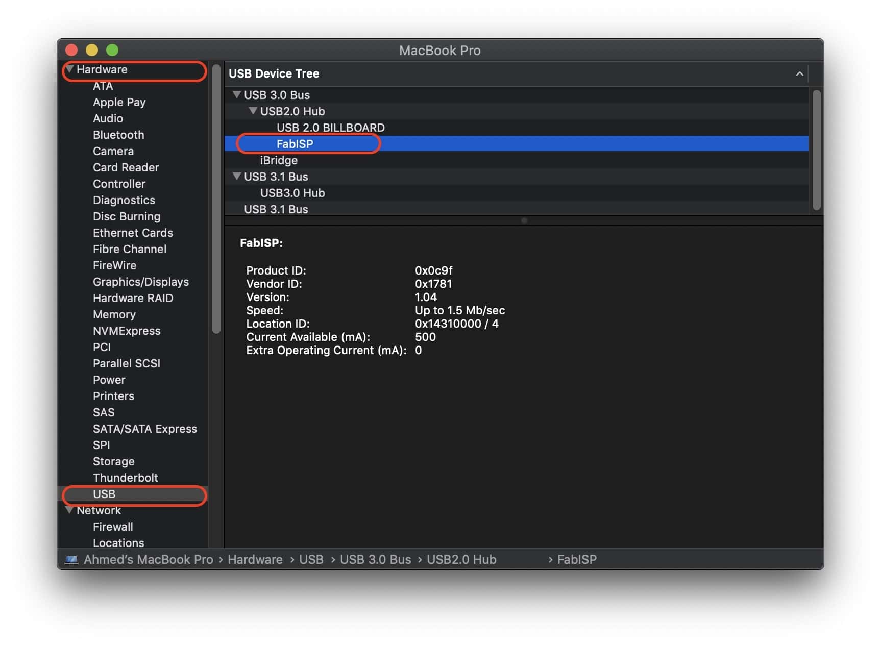
Then from the left side menu under the “Hardware” section click on “USB”. your programmer should be recognized by your computer with the name FabISB. Which means your AVR ISP is now ready to work!
Programming my first Board using my new FabISP(Bonus)
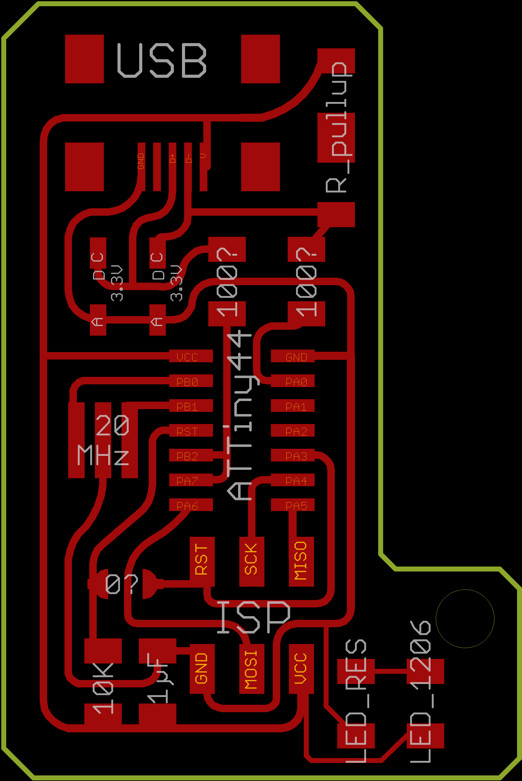
I was too excited to program any AVR-based board using my new programmer, specially it’s my very first time to make a programmer board. Since I have a previous experience with PCB designing using EagleCAD, I designed a very simple ATtiny44 based PCB that has two LEDs on it so I can program the board using my new programmer to make some cool blinking routine :D
I will not dive into the details of how I designed this board. If you are interested in that you can check the Electronics Design week Assignment.
ATTINY44A Two LEDs blinking PNG Files Download
I programmed this board using Arduino IDE, without diving in the programming details in this tutorial. If you wanna know more about this topic you can check my Embedded programming week Assignment.