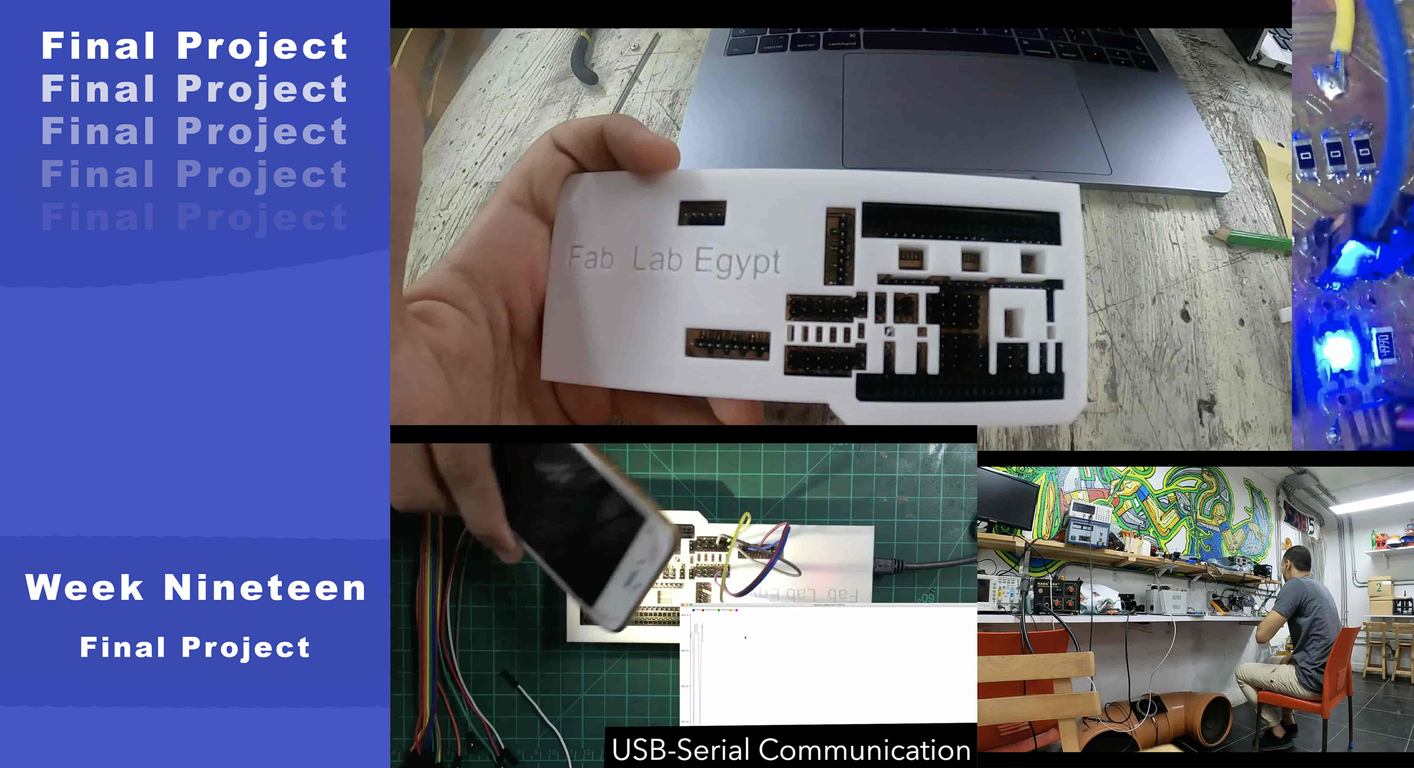
Final Project
What’s Going On?
As an electronics geek I love playing and tinkering with electronics. At the early stage of any electronic development process you're gonna find yourself using a breadboard to test your circuit if it’s working or not. I asked myself why we don’t have a breadboard for the SMD components? Not only that, Why not to have a breadboard for the SMD components with a built-in Atmega328 microcontroller chip that can get programmed as a normal Arduino UNO board through a USB connector?
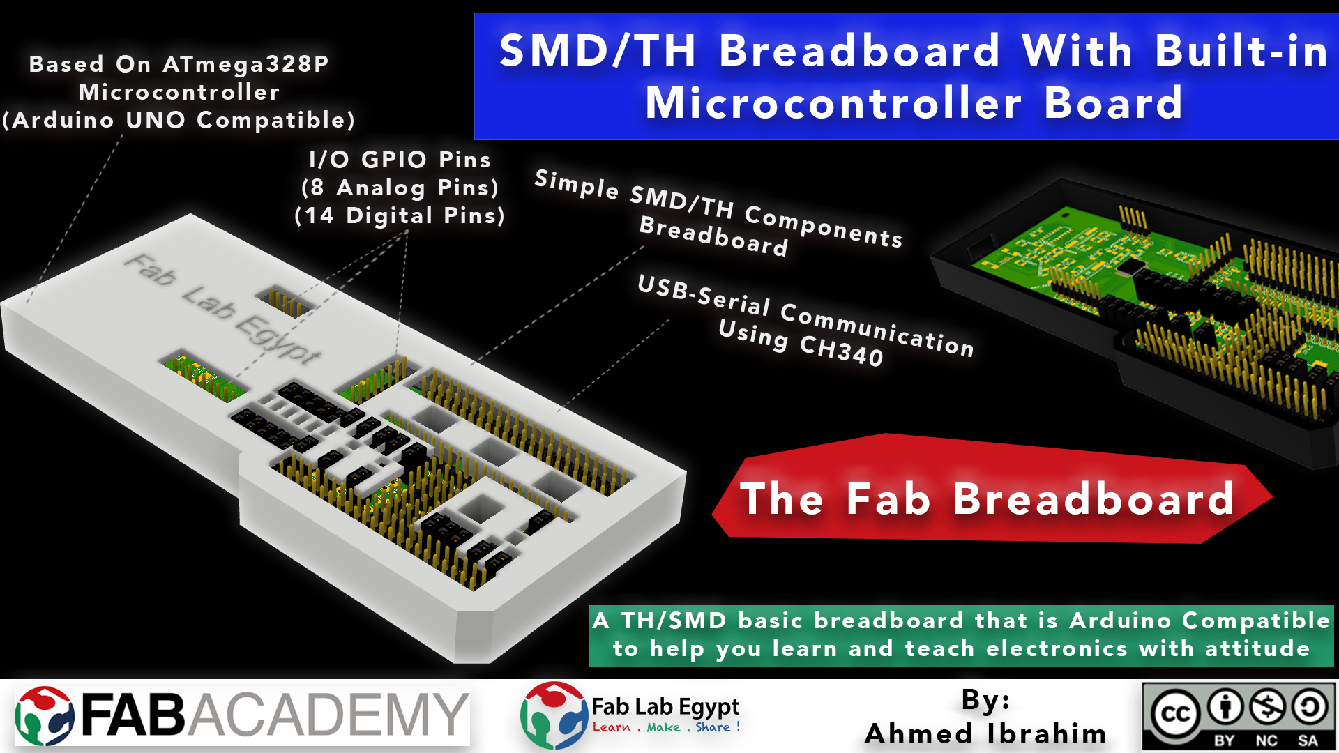
I started doing my research to see if there are any similar projects, I didn’t find any breadboards made specifically to be compatible with SMD components! But I found a normal breadboard compatible with through-hole components that has a built-in ATmea328P chip that can get programmed like an Arduino UNO! My project will combine these two things together in one combo. The breadboard will have a built-in ATmega328AU microcontroller with full access on it’s GPIOs. So, the user can get all the functionalities of a breadboard that is also compatible with the most-used SMD packages from the fab inventory and all the functionalities of the Arduino board in one package.
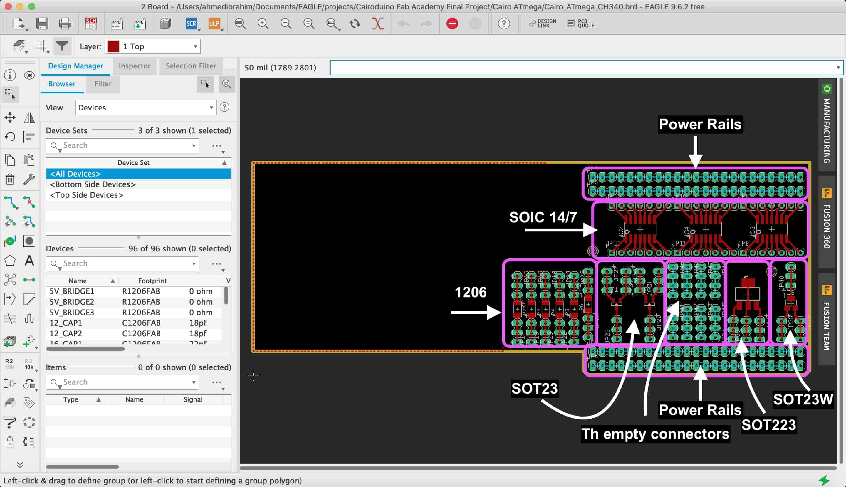
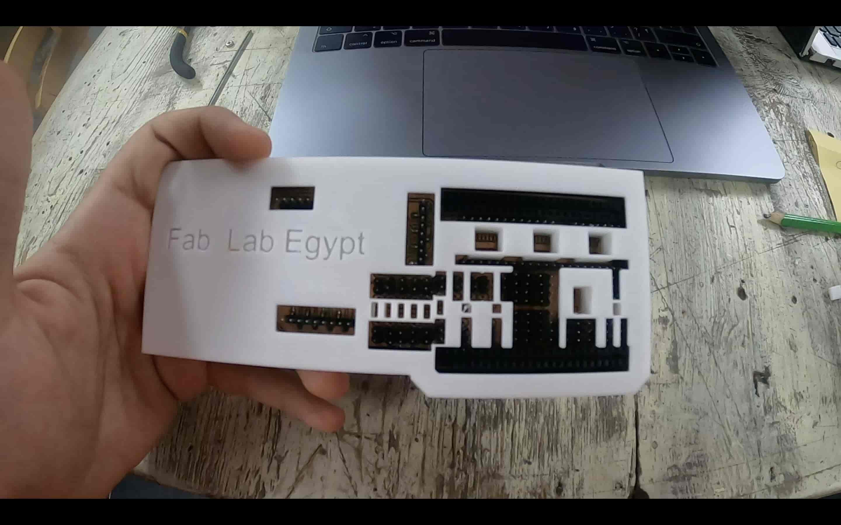
The Fab Breadboard is compatible with these SMD packages, 1206, SOT23, SOT23-W, SOT223, SOIC 7, SOIC14. These packages cover almost all the most-used SMD components in the fab inventory, like the LEDs, resistors, capacitors, phototransistors, AMS1117 voltage regulators, ATtiny44, ATtiny45, A4593 motor driver H-bridge, hall effect sensors, … and so on. Also, it has a specific place where you can insert the normal through-hole components in to make some cool stuff.
You can program the Fab breadboard using the Arduino IDE with the Arduino C programming language. The built-in ATmega328P-AU chip has the Arduino UNO bootloader uploaded to it. So, it’s 100% Arduino UNO compatible.
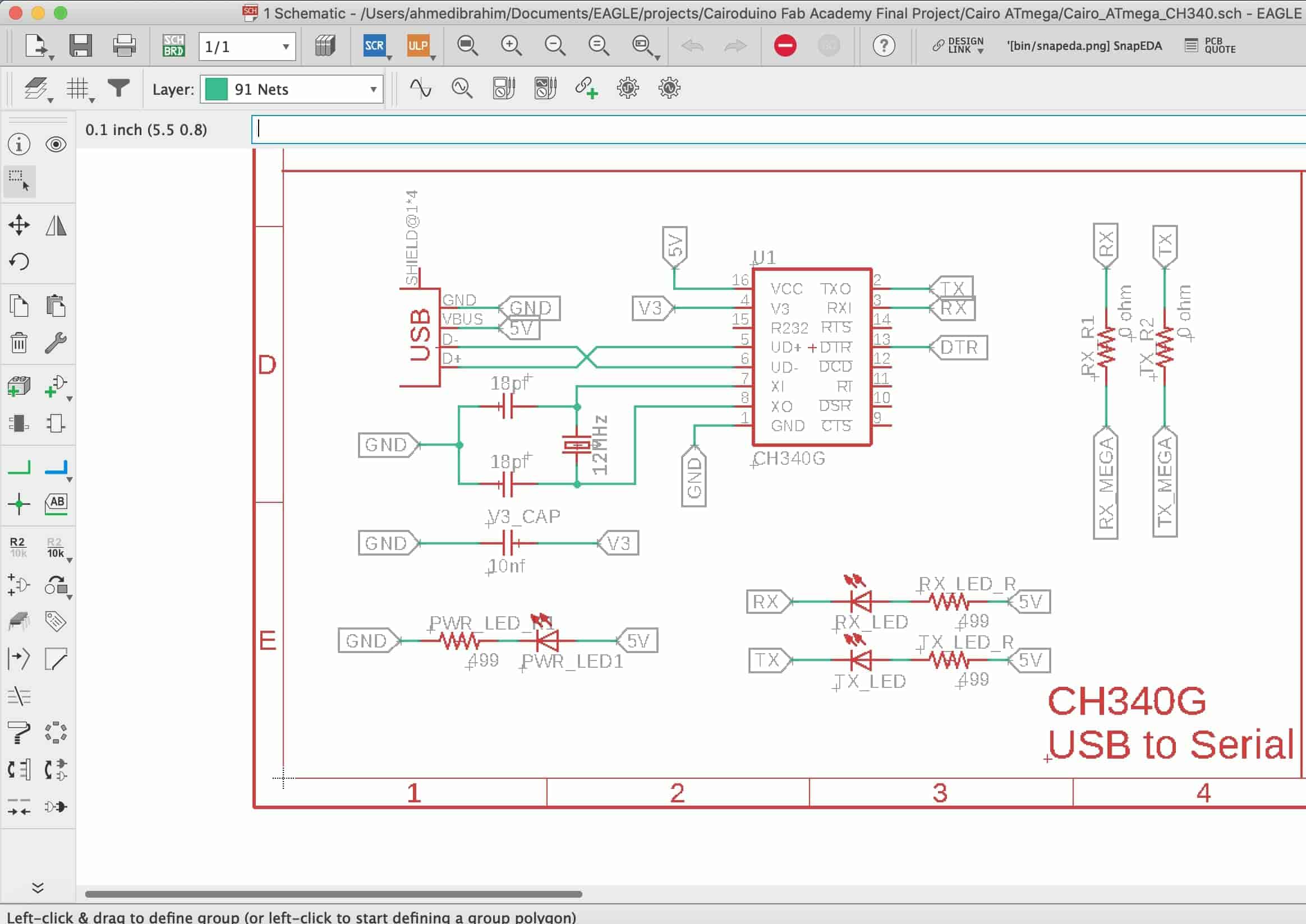
The Fab breadboard has a built-in CH340G USB to serial communication converter IC to make it easy for the user to establish a serial communication between the fab breadboard and the PC/laptop. Also, to make uploading the code to the Fab breadboard easily without the need to use an AVR programmer.

Fab Breadboard by Ahmed Ibrahim is licensed under a Creative Commons Attribution-ShareAlike 4.0 International License.
How does the Development Process Go?
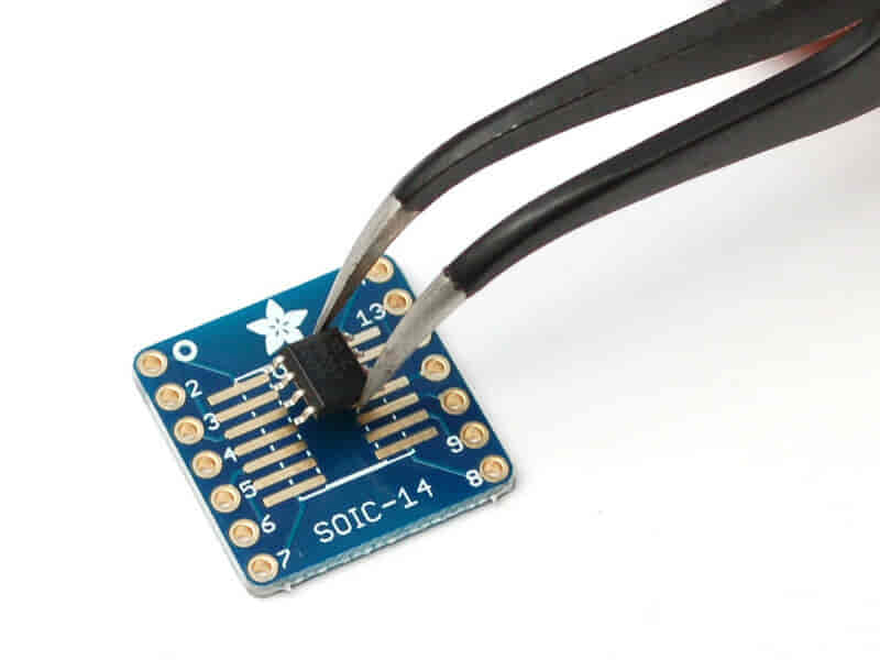
I got the idea concept and I understand what I need to build but still I wanna test if the idea concept is applicable and doable or not. I remembered a part from Neil’s lecture where he used the 3*2 AVR ISP header on a PCB without soldering it to save some space on the board. He placed the AVR ISP header above its pads and applied some force on it until he finished uploading the code to the board then he removed the AVR ISP header back from the board. I decided to try that method and if it succeeds I will go on the same track. I buyed this test board from a local electronics store and placed an ATtiny45 IC on it and tested the current continuity between the IC leg and the PCB pad using an AVO and it’s working like a charm!
Now I’m pretty sure that concept is doable. Before any designing work, let me explain to you what the Fab Breadboard consists of?
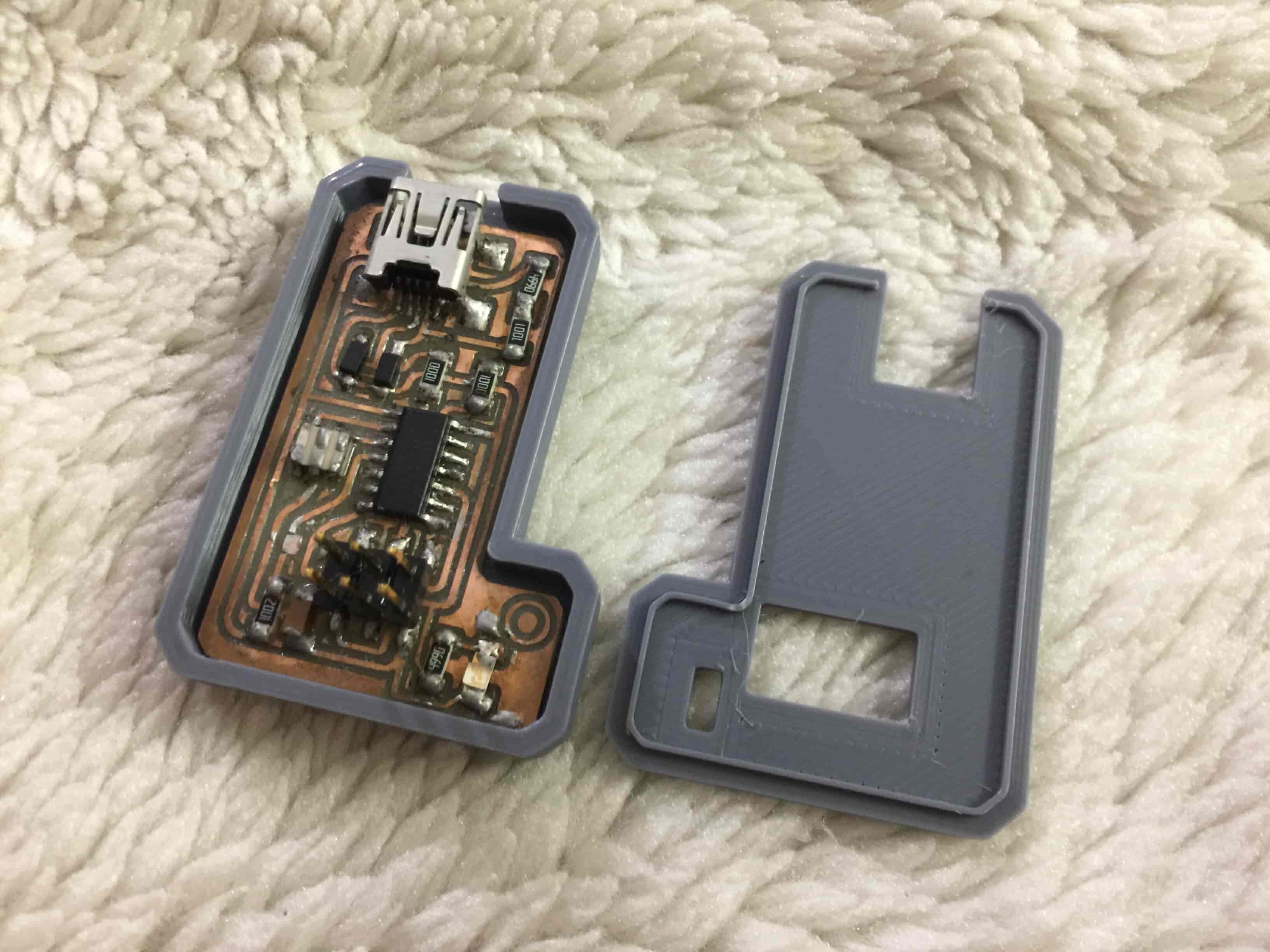
- Simply, it consists of a PCB that contains the brain, the ATmega328P-AU chip, different SMD footprints that cover the fab inventory most-used SMD components as we stated before, CH340G USB to Serial converter IC, female pin headers for the Through-hole components.
- A 3D-printed enclosure that keeps all the SMD components in place.
Designing The Fab Breadboard PCB
Why CH340G with ATmega328P? Ok, The 328p is the chip that is used with the Arduino Uno, but it doesn't have a native USB connection, which is useful for easily uploading new programs to it. This means we must use an external programmer or another chip to program it and pass serial data. In the Uno this is done by another ATmega microcontroller, the 16u2. But these chips are a bit more complex than is really necessary. Usually an FTDI FT232R would be used instead. But here in Fab Lab Egypt the smallest end mill we have is the 0.4mm which can’t cut between the FT232R pads because the clearance between them is very very small. So, I decided to use the CH340G which has a larger clearance and is machinable with the 0.4mm end mill.
Before starting any kind of designing we need to understand how these chips work, their electrical requirements, pinout, and typical application. All these data are available in the chip datasheet which I covered in detials in the Embedded Programming Week.
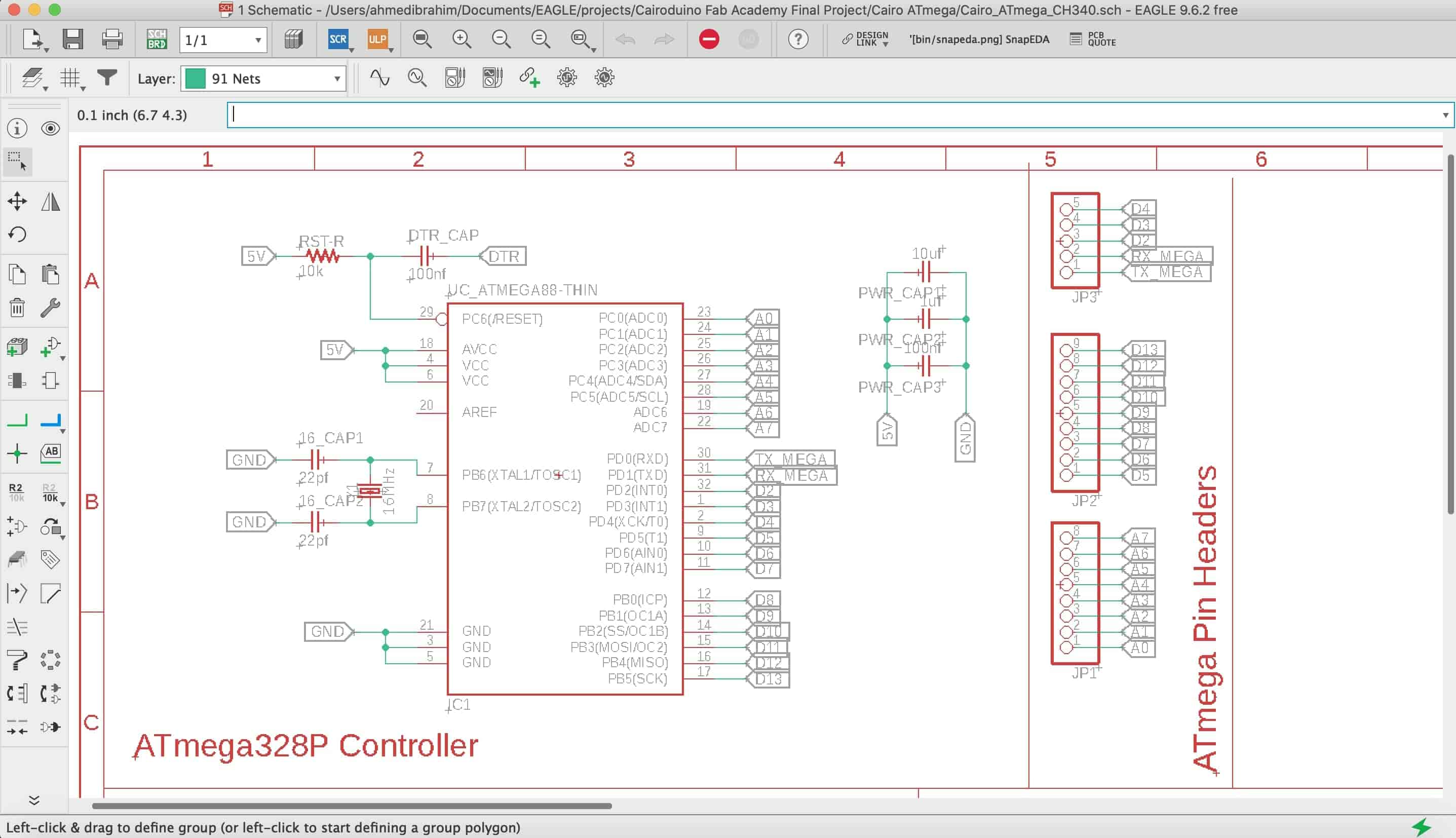
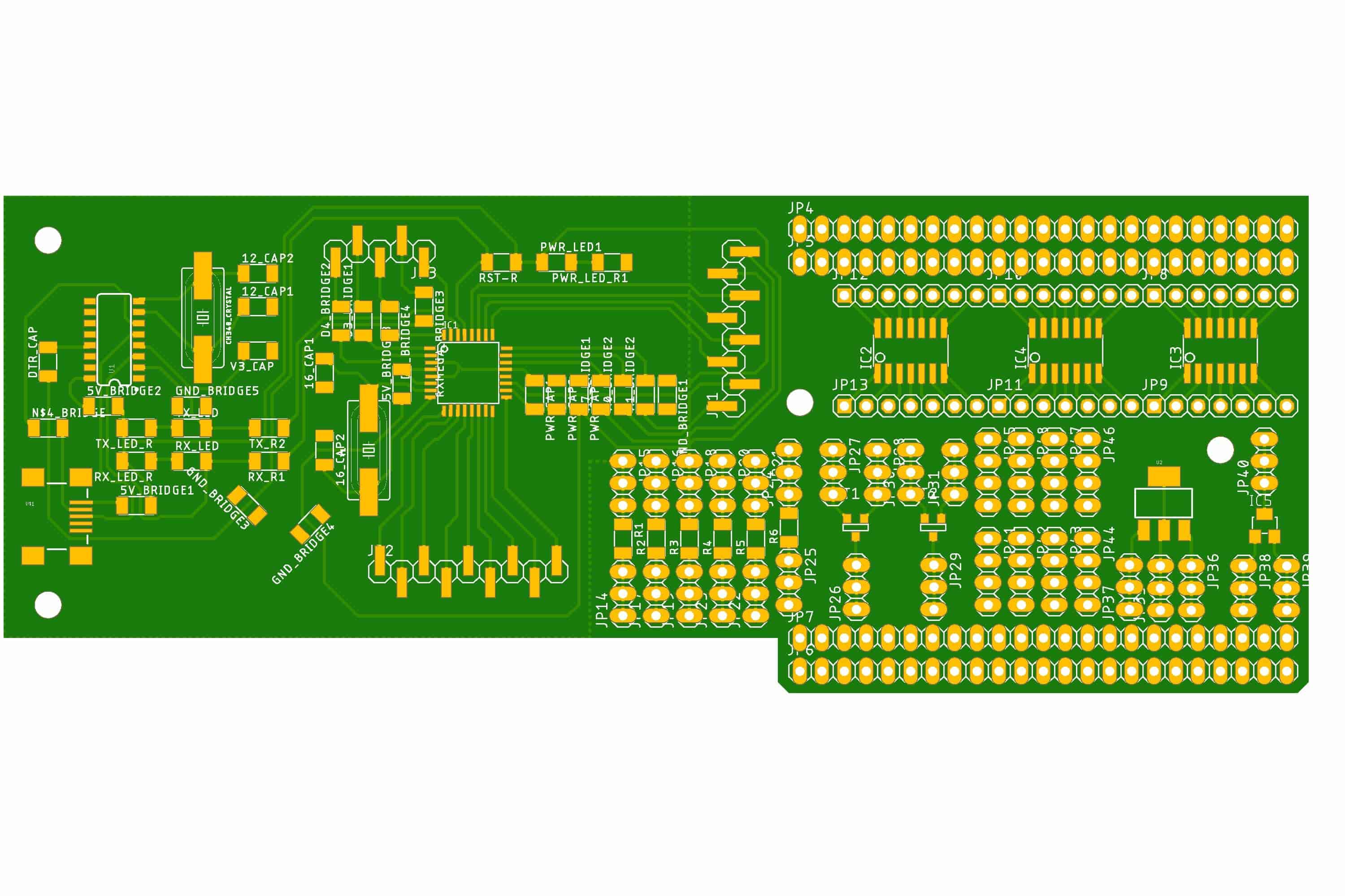
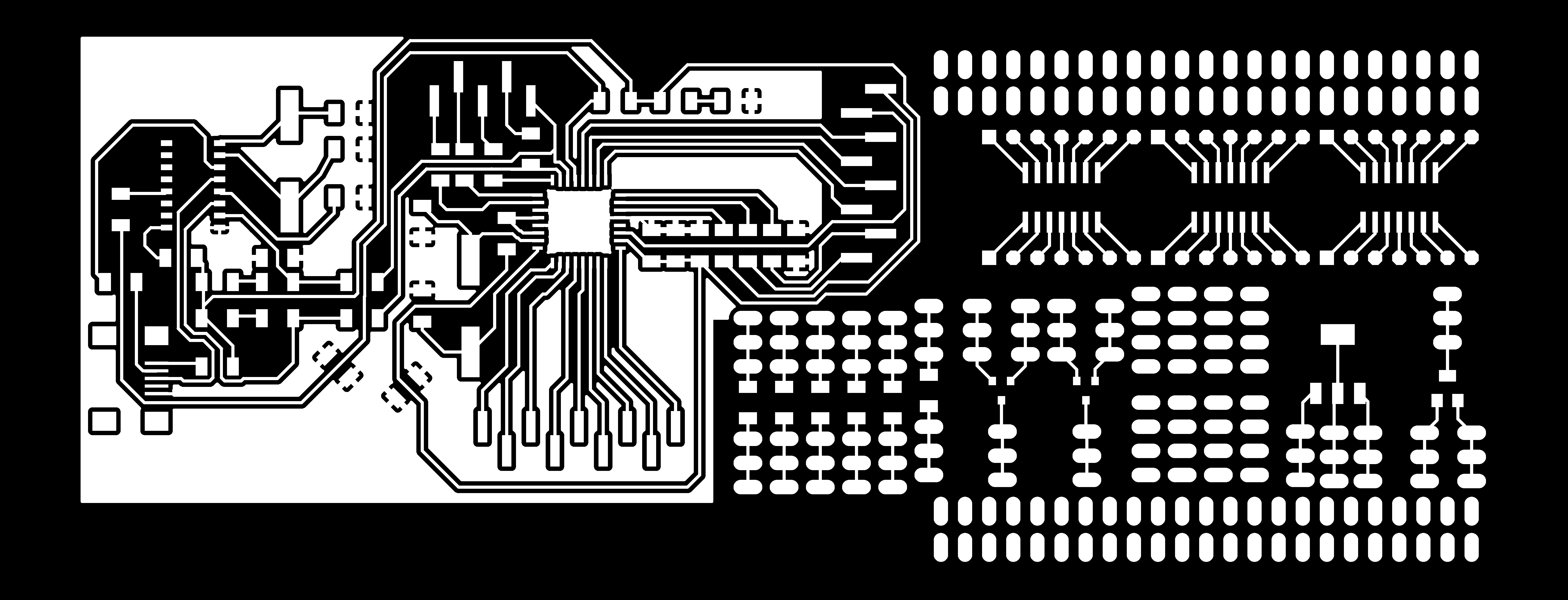
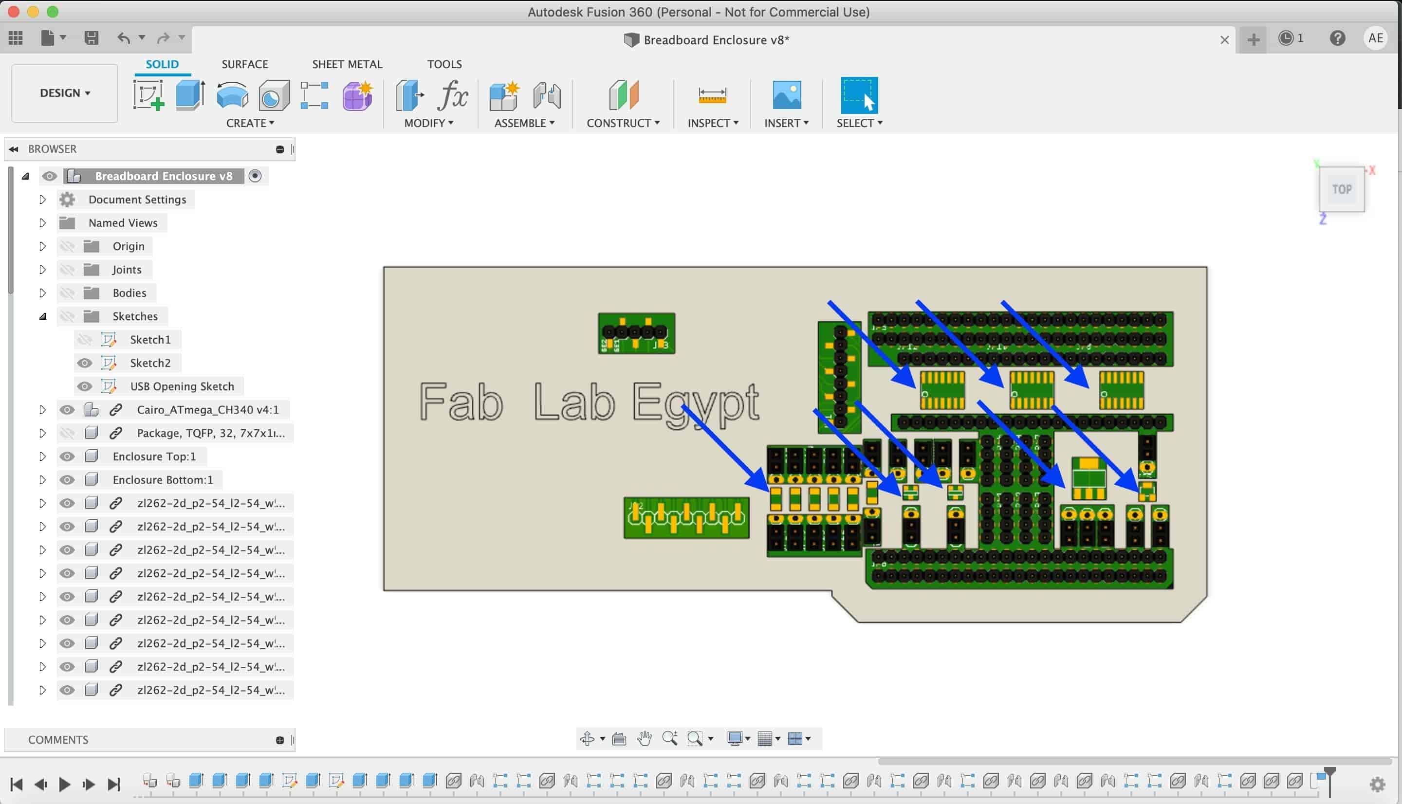
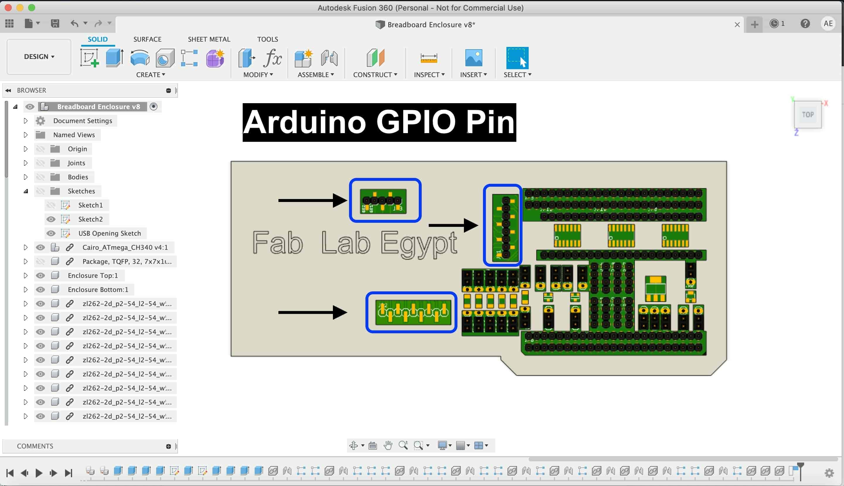
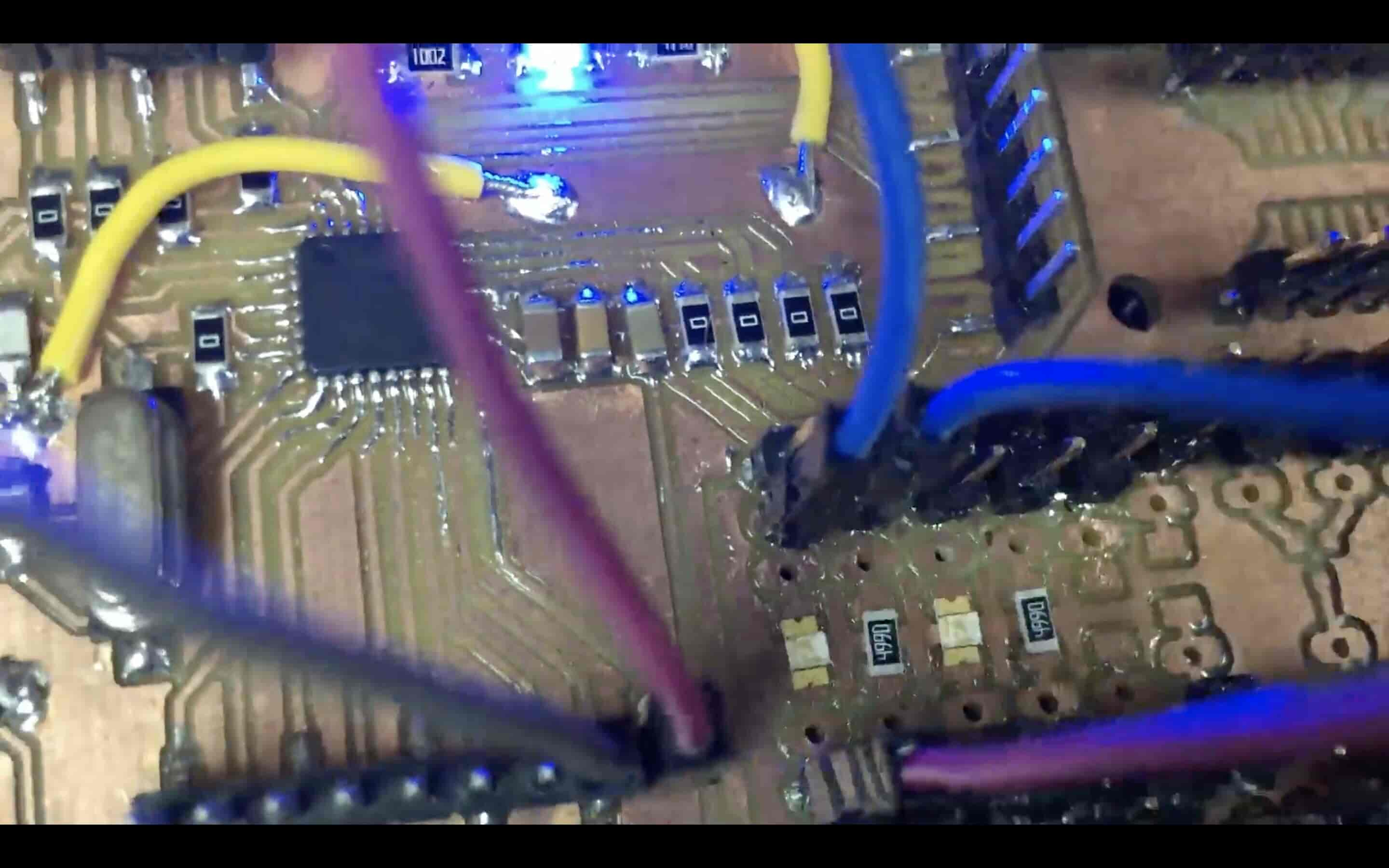
After finishing the ATmega328P-AU microcntroller and CH340G circuit schematic. I converted into the PCB layout and started laying the components footprint down with the PCB space in mind. I tried to save as much space as I can for the SMD breadboard section. In the image below, you will find the Fab breadboard ATmega328P-AU chip Arduino pin mapping.
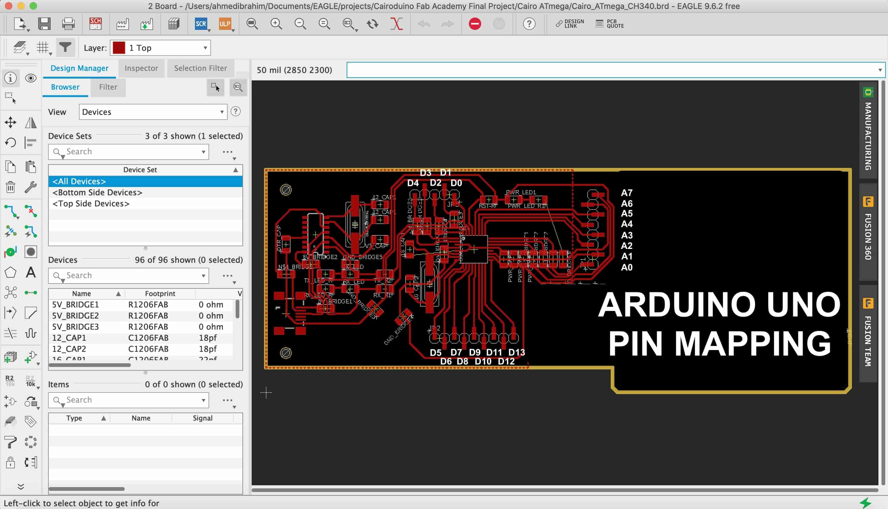
The important part here, we break out the ATmea328P-AU microcontroller GPIO pins on some pin headers to give the ability to the user to access these pins and connect it to his/her devices simply through some jumpers.
Now, we designed the brain, the ATmega328p & the CH340G circuit. Let’s design the breadboard part. SMD components have very very large different packages with so different sizes. So, how will the breadboard be able to deal with all these different dimensions?! I thought about making the first prototype compatible with different 5 or 6 packages. Trying to cover the most popular SMD components from the Fab Inventory as we stated before. With these packages, I can build a super cool circuit As a proof of concept!
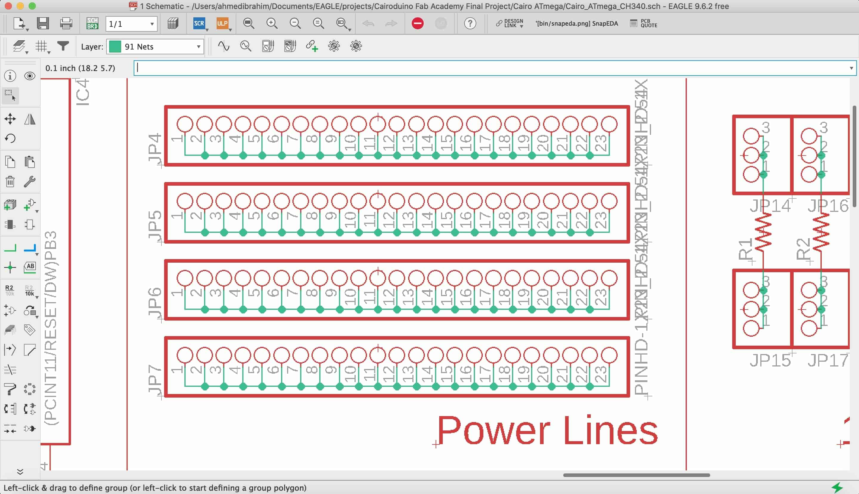
First step, I wanna add four female pin headers for the power rail part, two pin headers for the positive rails, and another two pin headers for the negative rail. Each two pin headers are on one side of the PCB. I connected each pin in a line together.
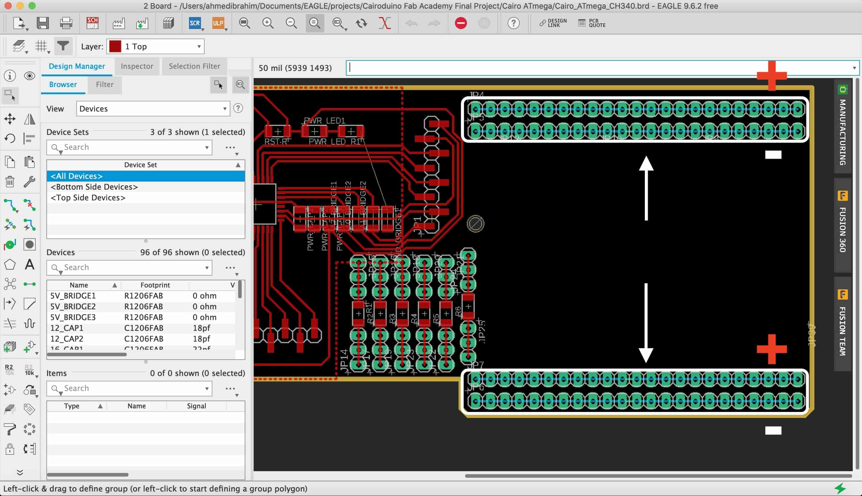
Then I converted into the board layout and started placing the components that I inserted in my schematic so far. The Below image explains how I place the four pin headers.
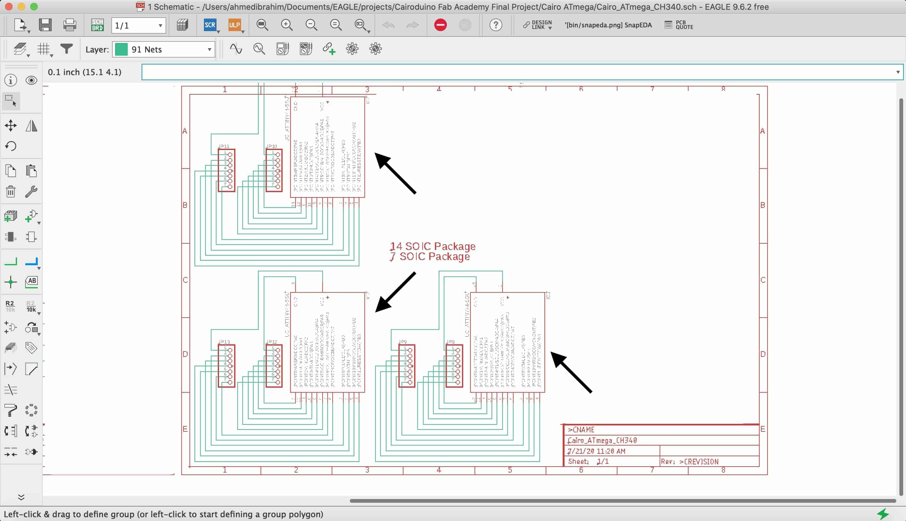
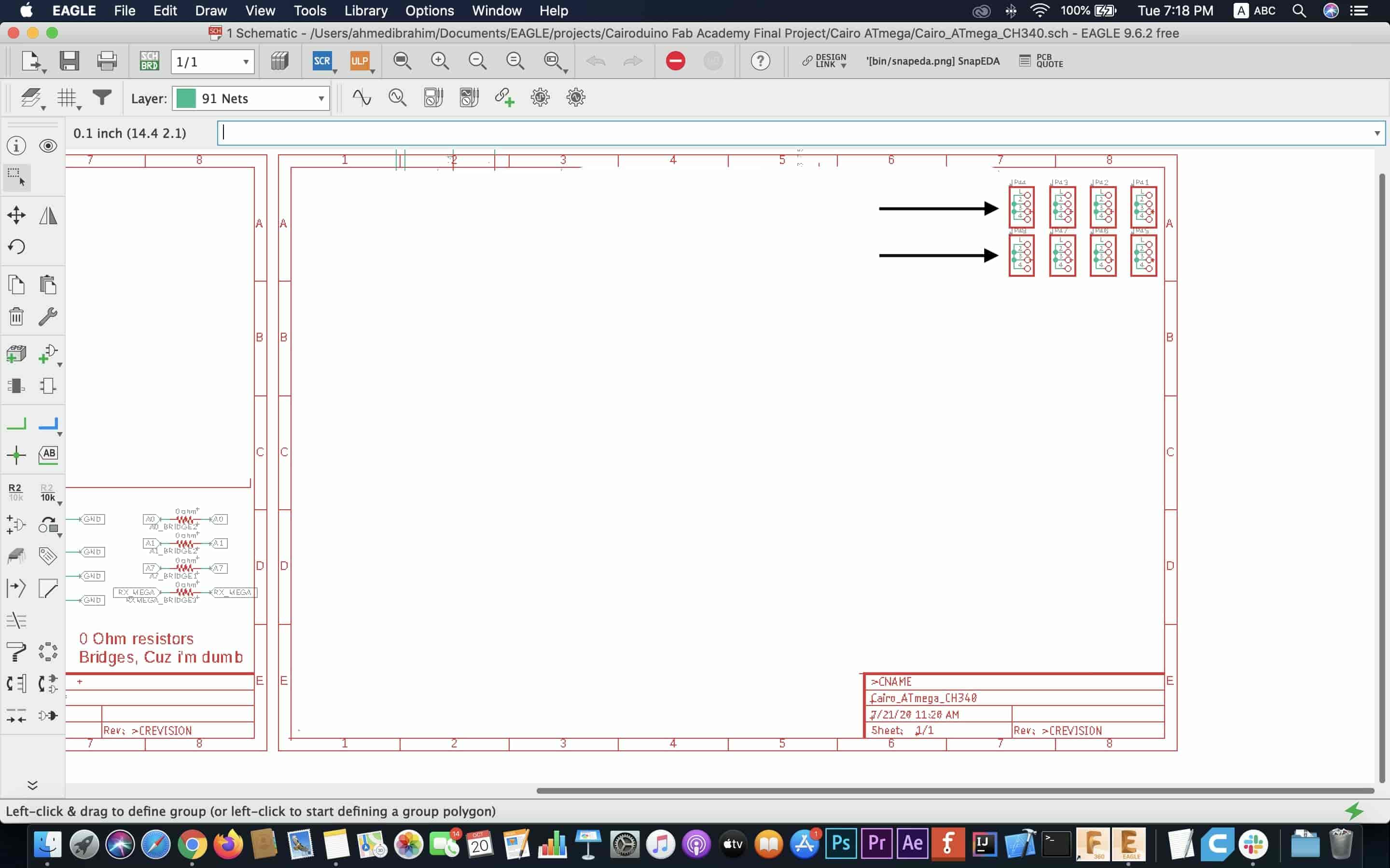
Then I started adding the SMD packages footprint that will be used later on to mount the SMD components on it. I started with the 14SOIC Package. It will cover the 7SOIC package as well. I connected it’s pins to some male pin headers to allow the user to use these pins using through some jumper wires.
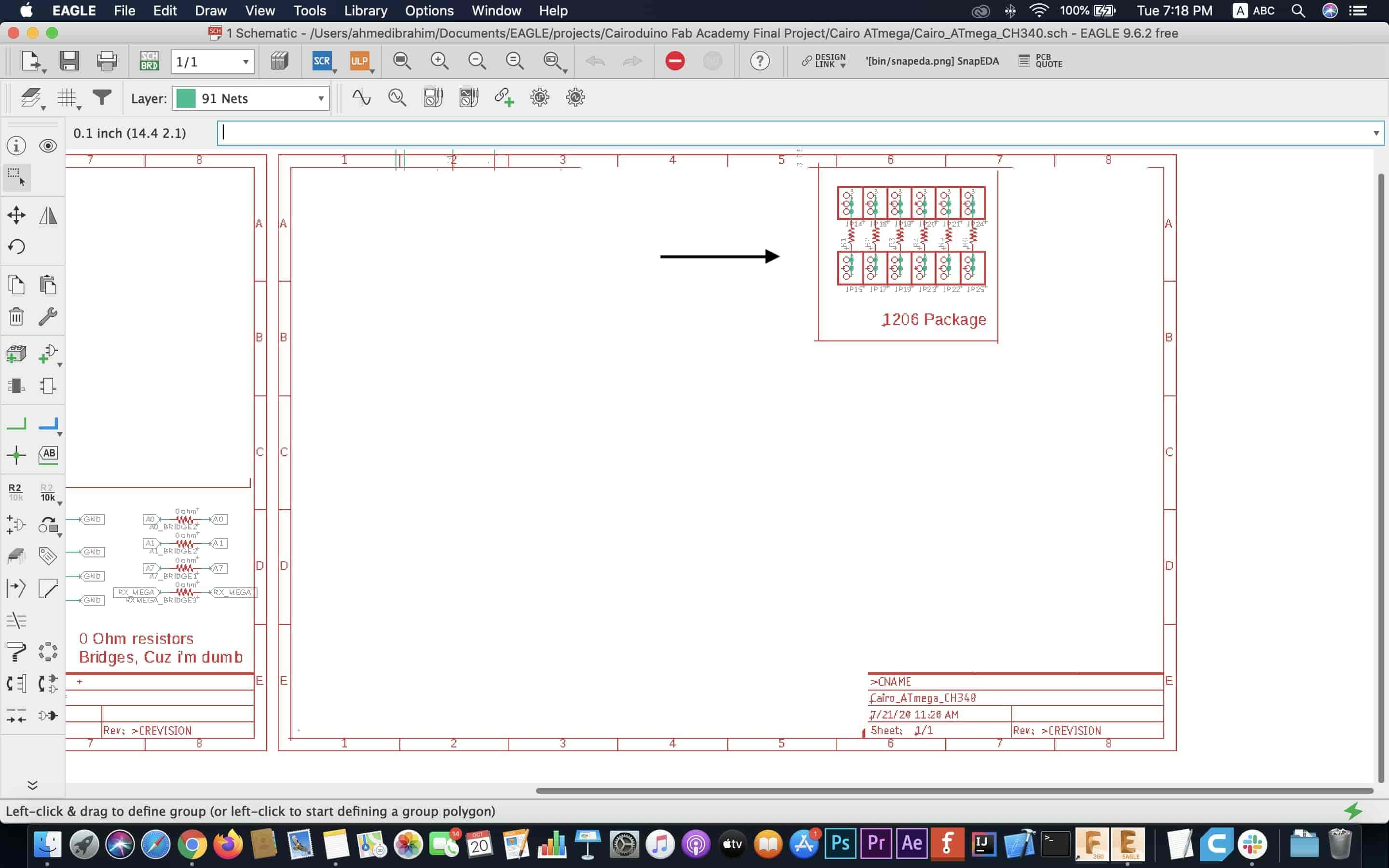
After that I added the SMD1206 package and exposed it’s pins using some male pin headers as well.
Then, I added some empty female pin headers to give the option to the user to connect anything on these pin headers.
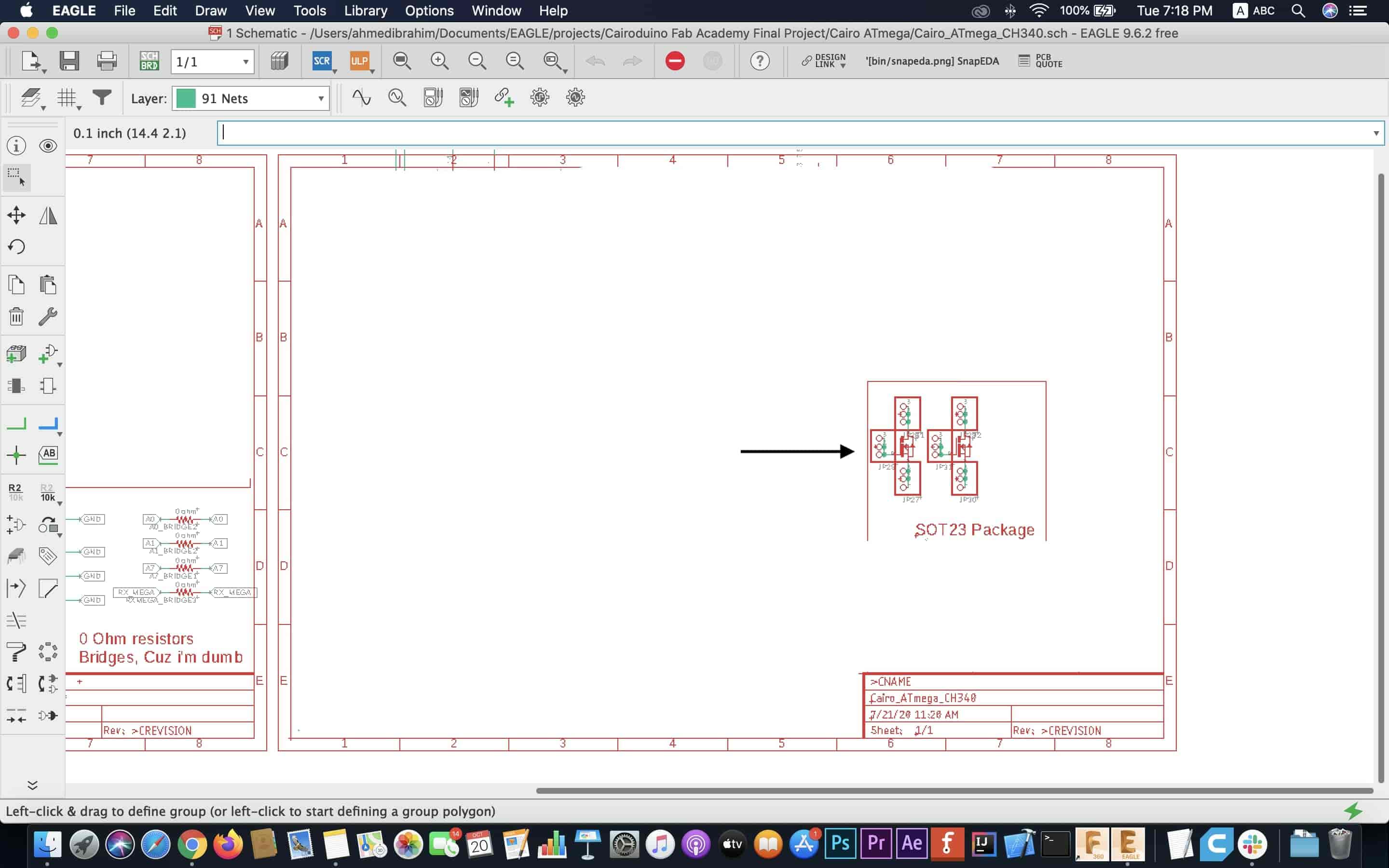
Also, I added some SOT23 packages to the fab breadboard and connected it’s legs to some female pin headers..
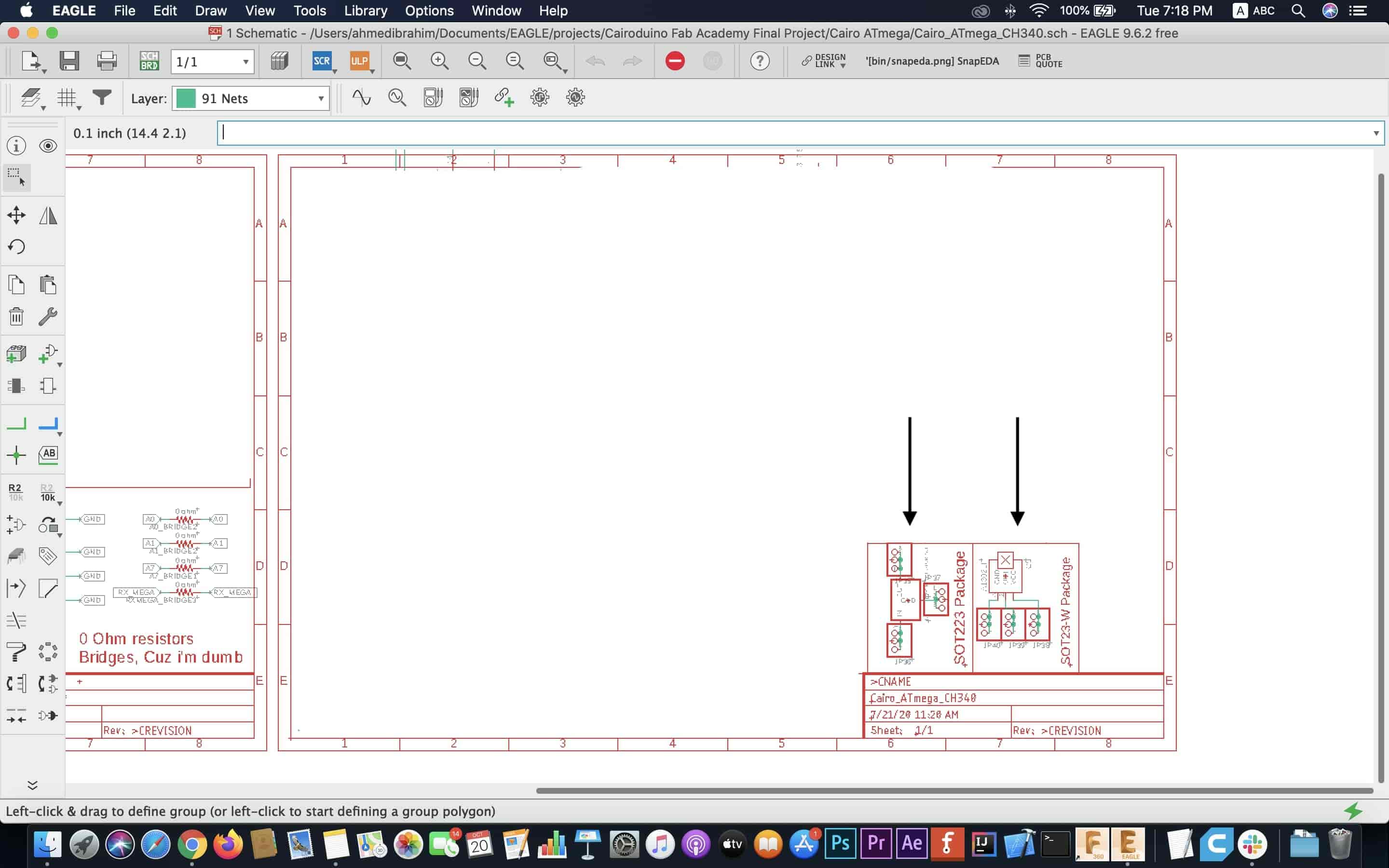
Finally, I added some SOT223 and SOT23W packages and connected it’s legs to some female pin headers as well so the user will be able to access these legs using some jumper wires.
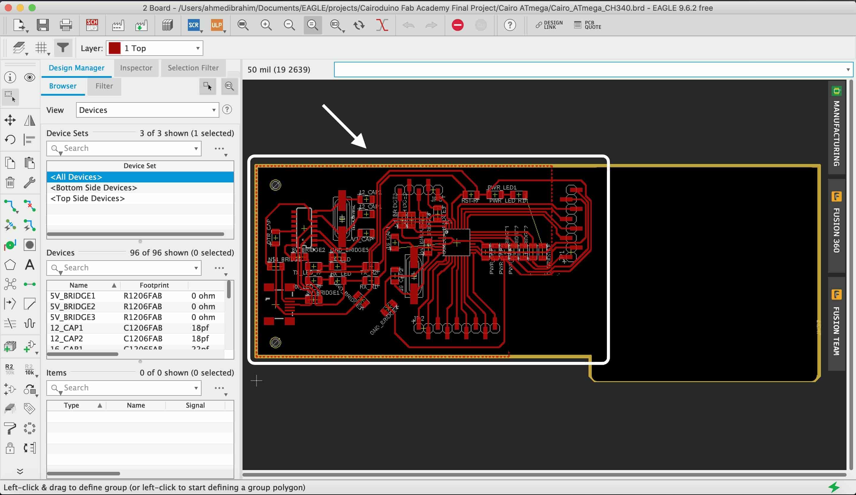
Now, after all the SMD packages are added to the board schematic, it's time to do some board layout. I converted into the board layout and started placing the components carefully inside the board outline keeping the board dimensions and the modela machine design rules in mind.
Now, the PCB designing is done(hopefully!) and we are ready to put the face mask on and take the microbus to the greatest Fab Lab ever, Fab Lab Egypt. To start the fabrication process. But wait! We need to prepare our fabrication files first. I used Gimp to do some post processing work on the PCB PNG images to export the traces and the outline both in separate different files. If you wanna know more details about this part specifically, check out the Electronics Production Week.
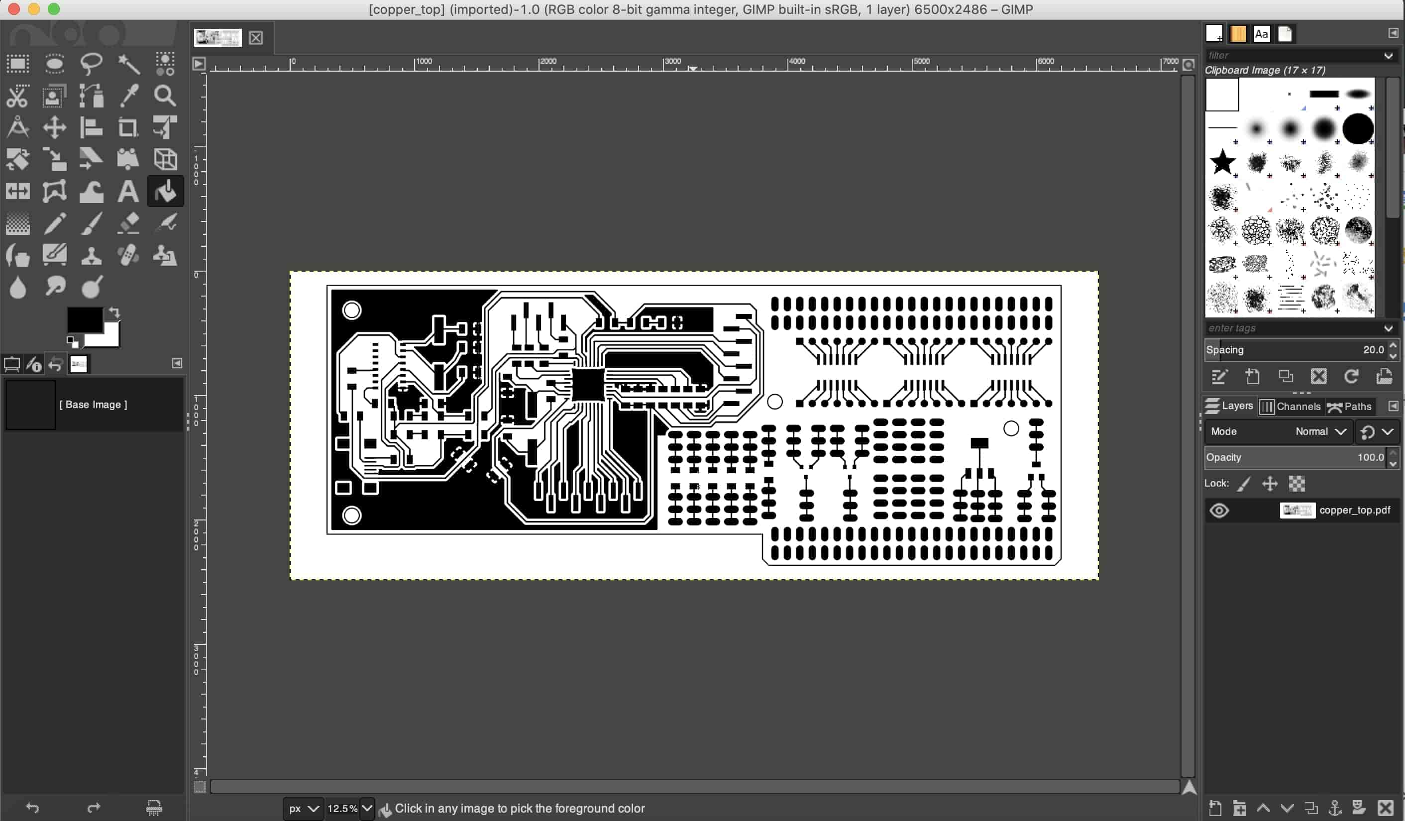
After doing some tweaks and edits on Gimp, I exported the PNG images to get ready for the fabrication work.


PCB PNG Files Download
- PCB Top Traces.
- PCB Bottom Traces Flipped.
- Board Profile Flipped.
- Board Profile.
- drills.
- drills Flipped.
- .SCH File.
- .BRD File.
Fabricating & Soldering The Fab Breadboard PCB
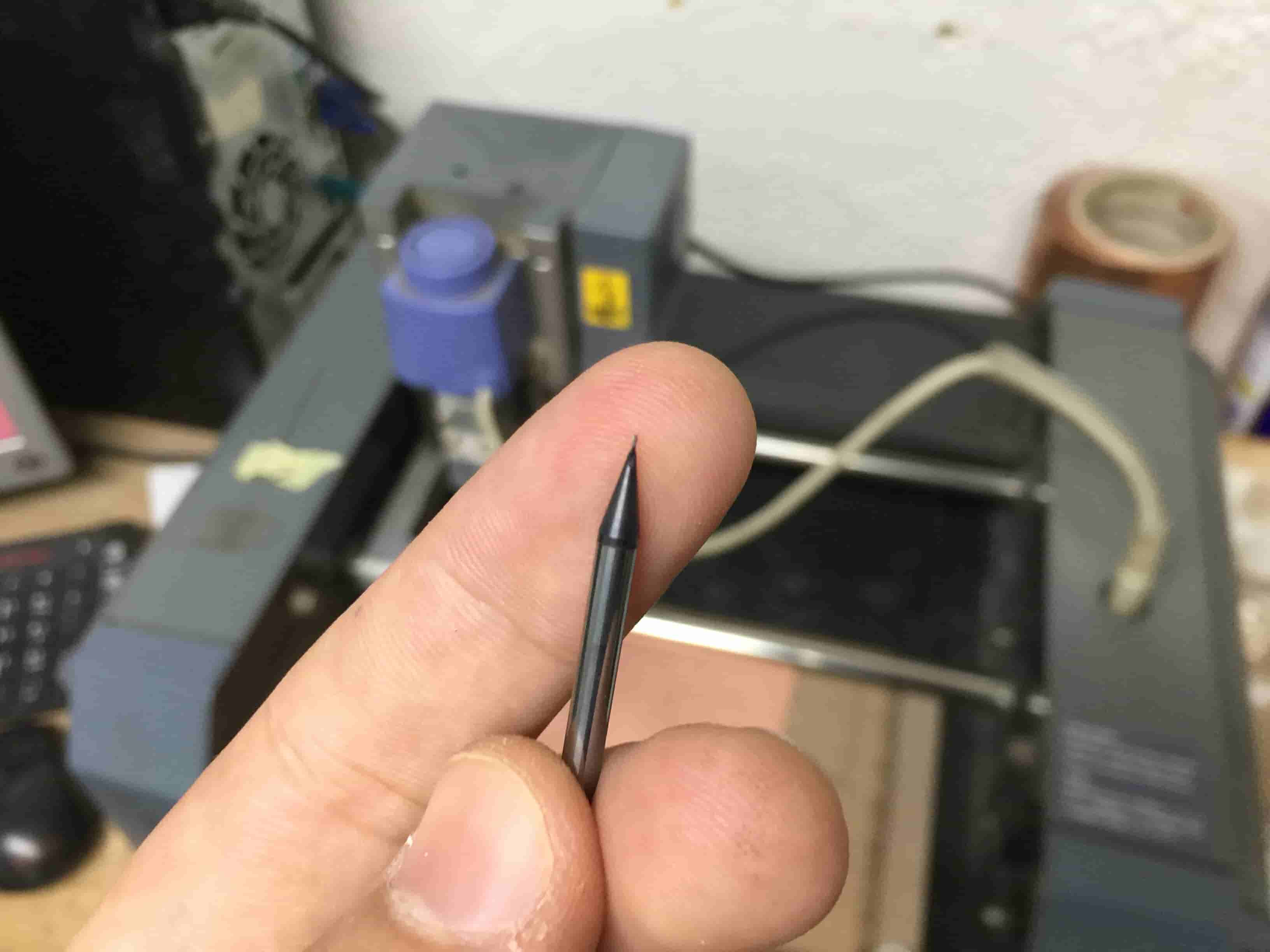
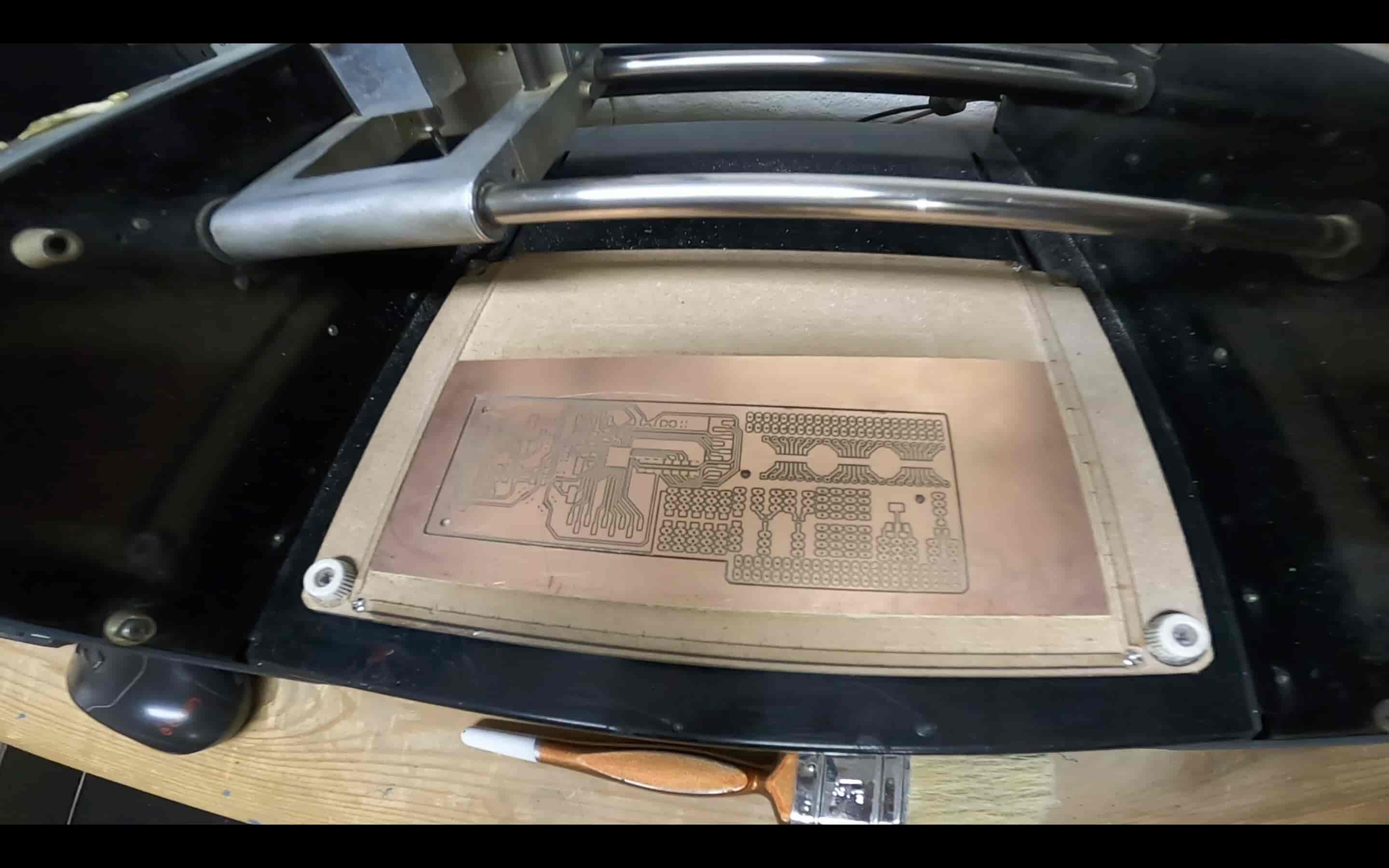
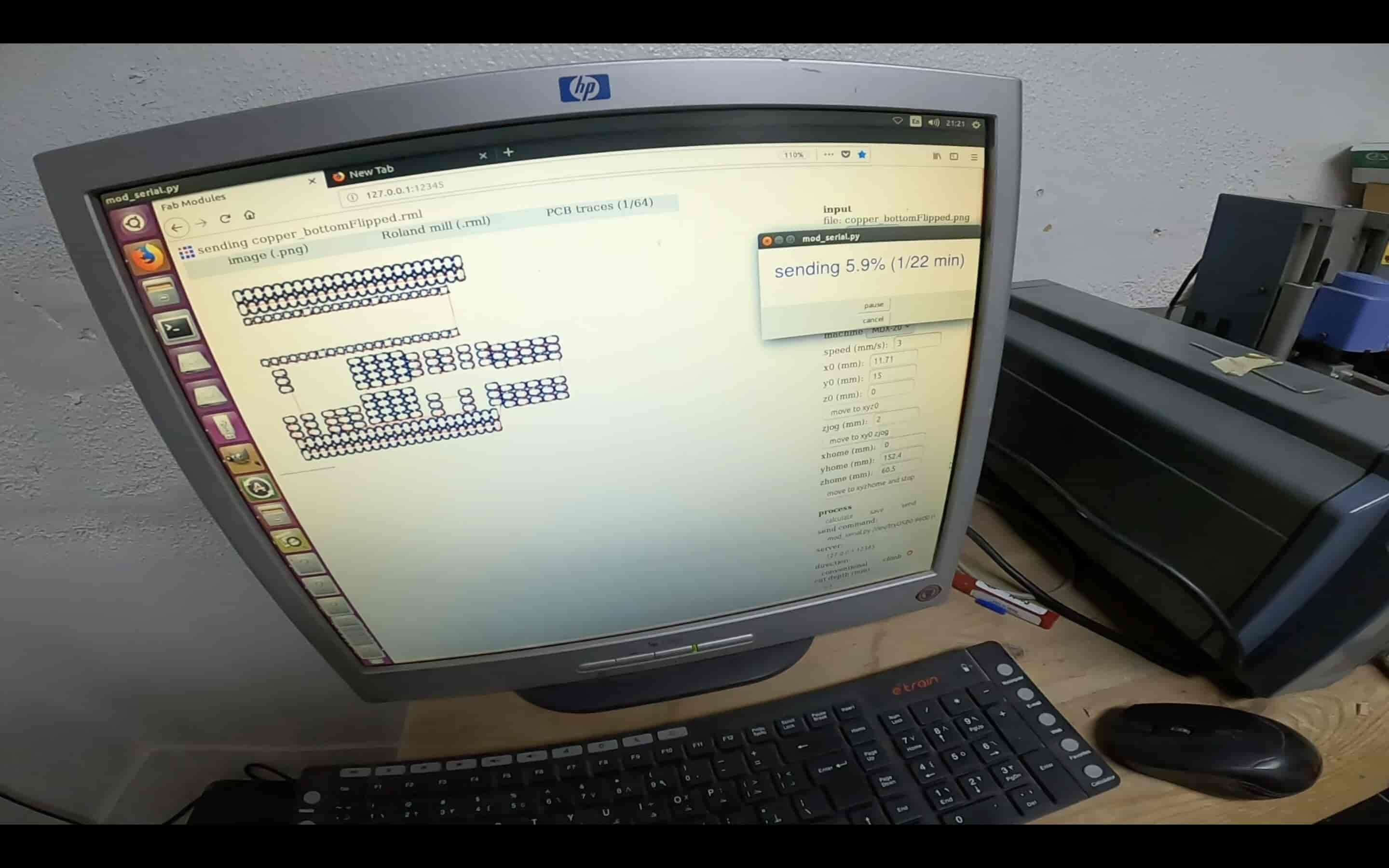
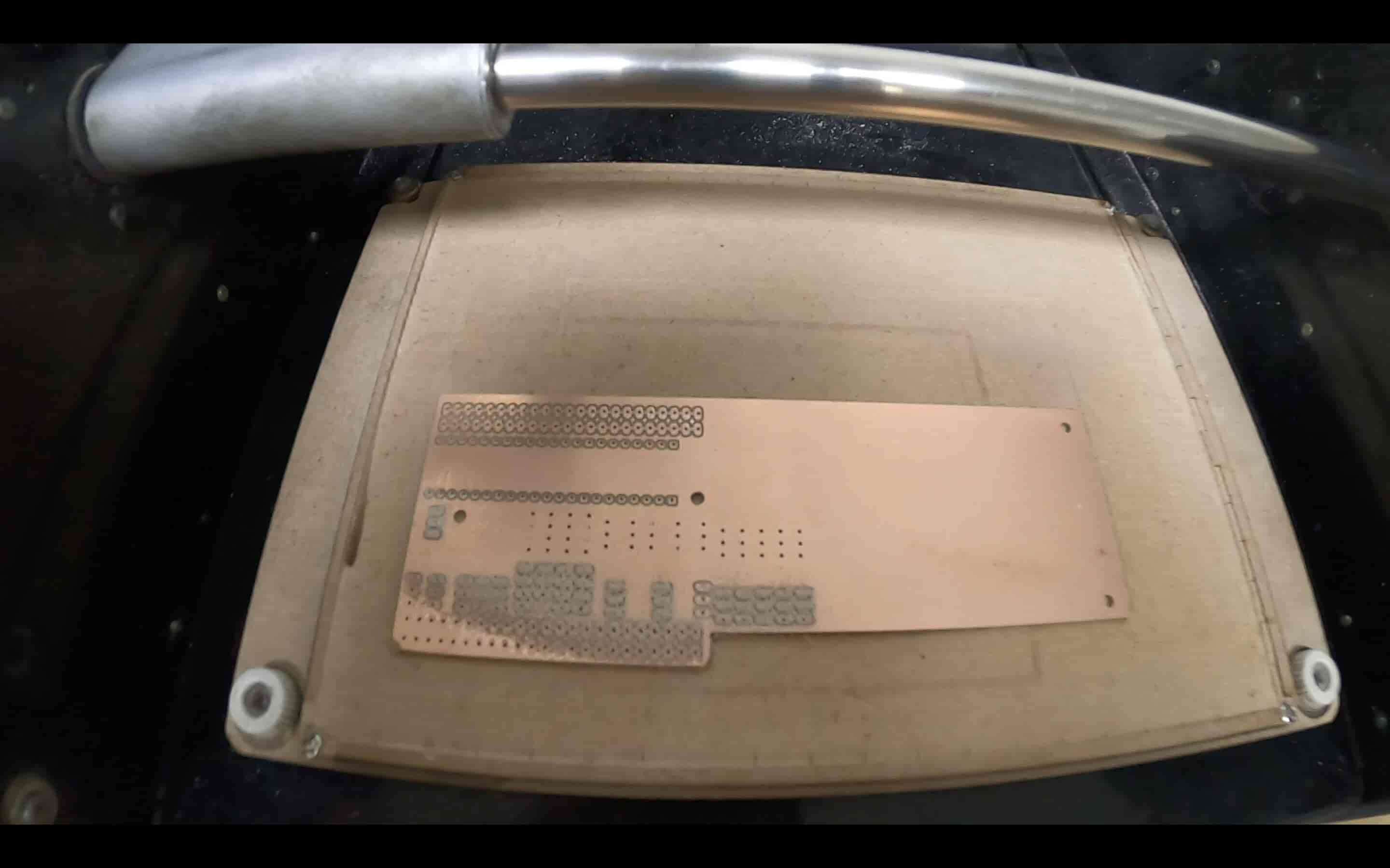
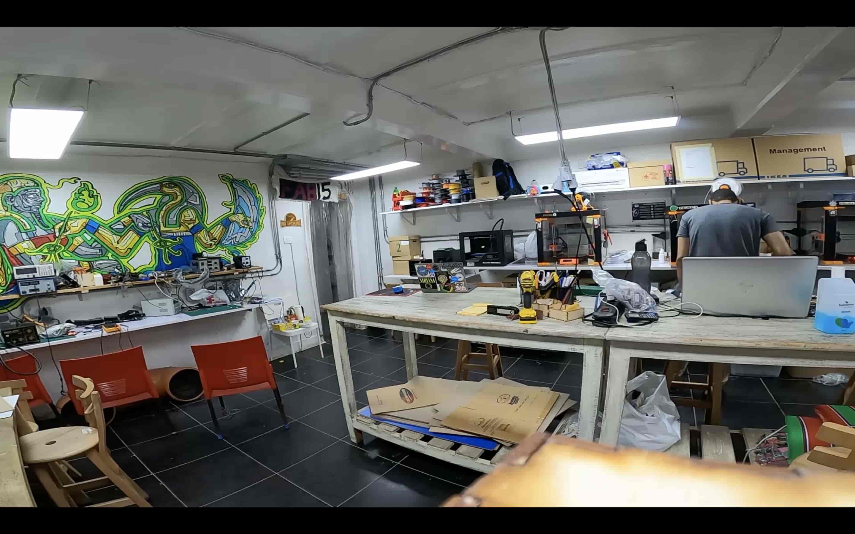
We have in Fab Lab Egypt a very beautiful Roland MDX-20 PCB milling machine. I used it with a 1/64inch end mill to fabricate my PCB top & bottom traces. Then, I used a 1/32inch end mill to cut the board outline.
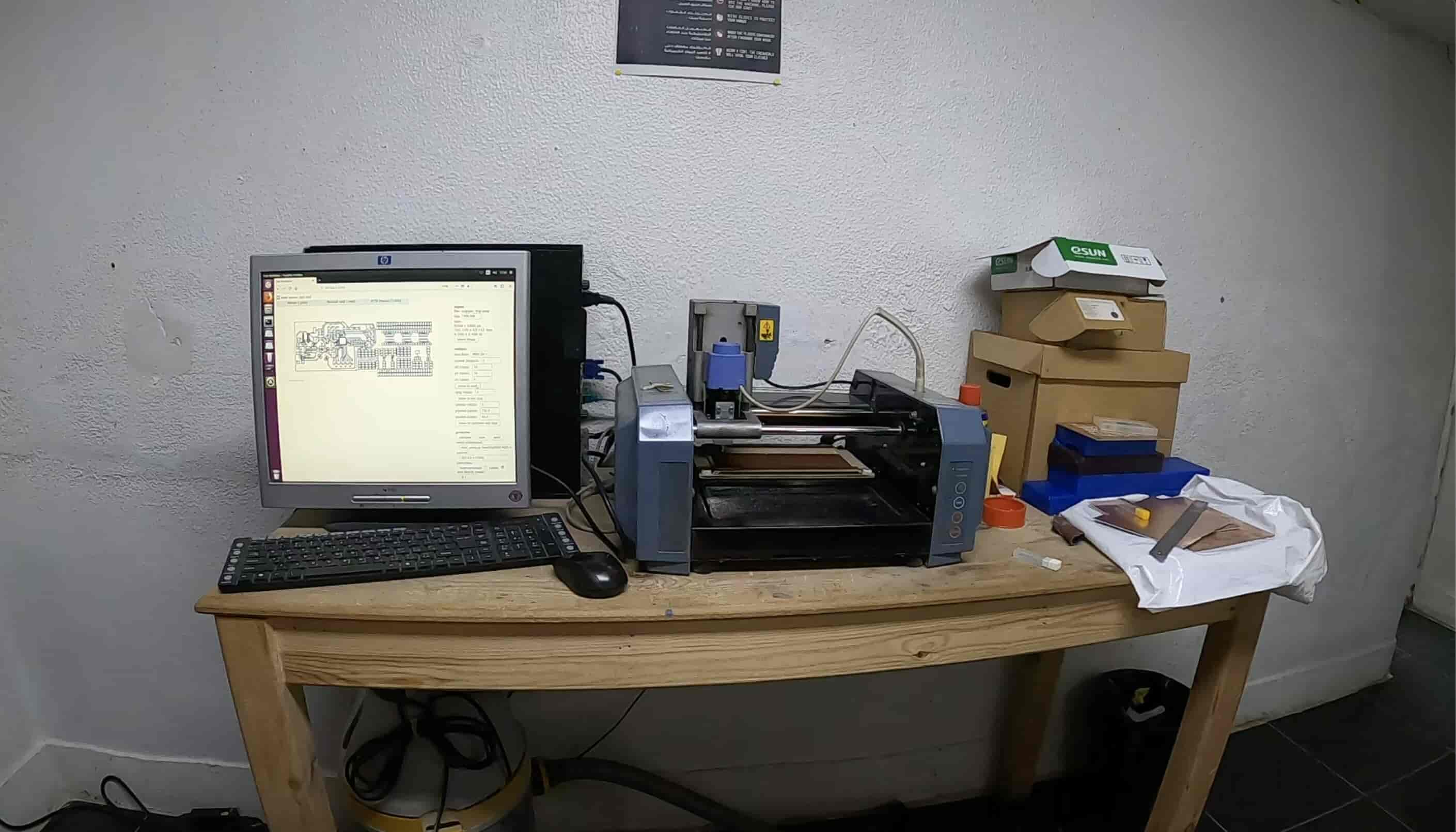
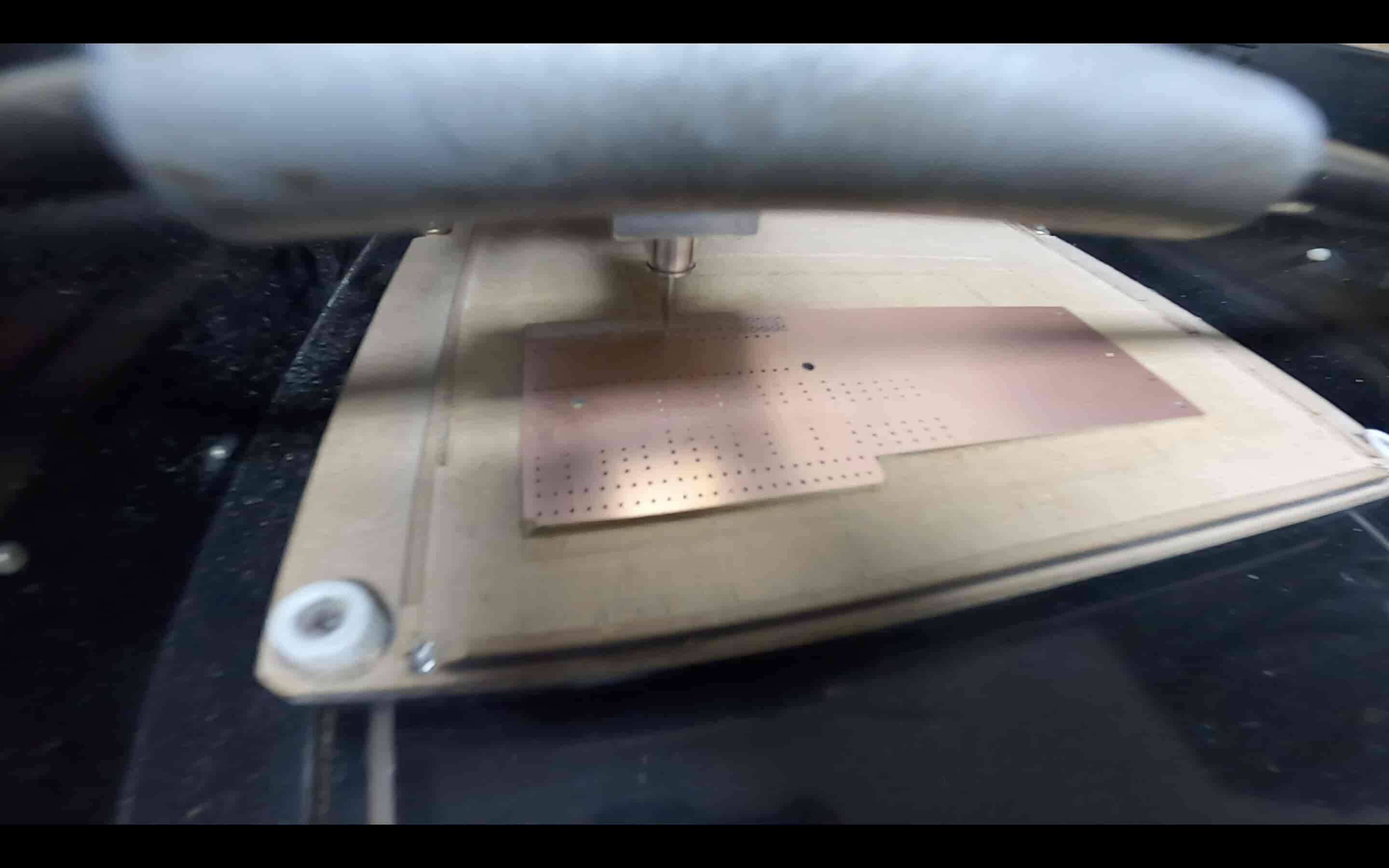
After finishing traces, I did the drills using a 1/32inch end mill.
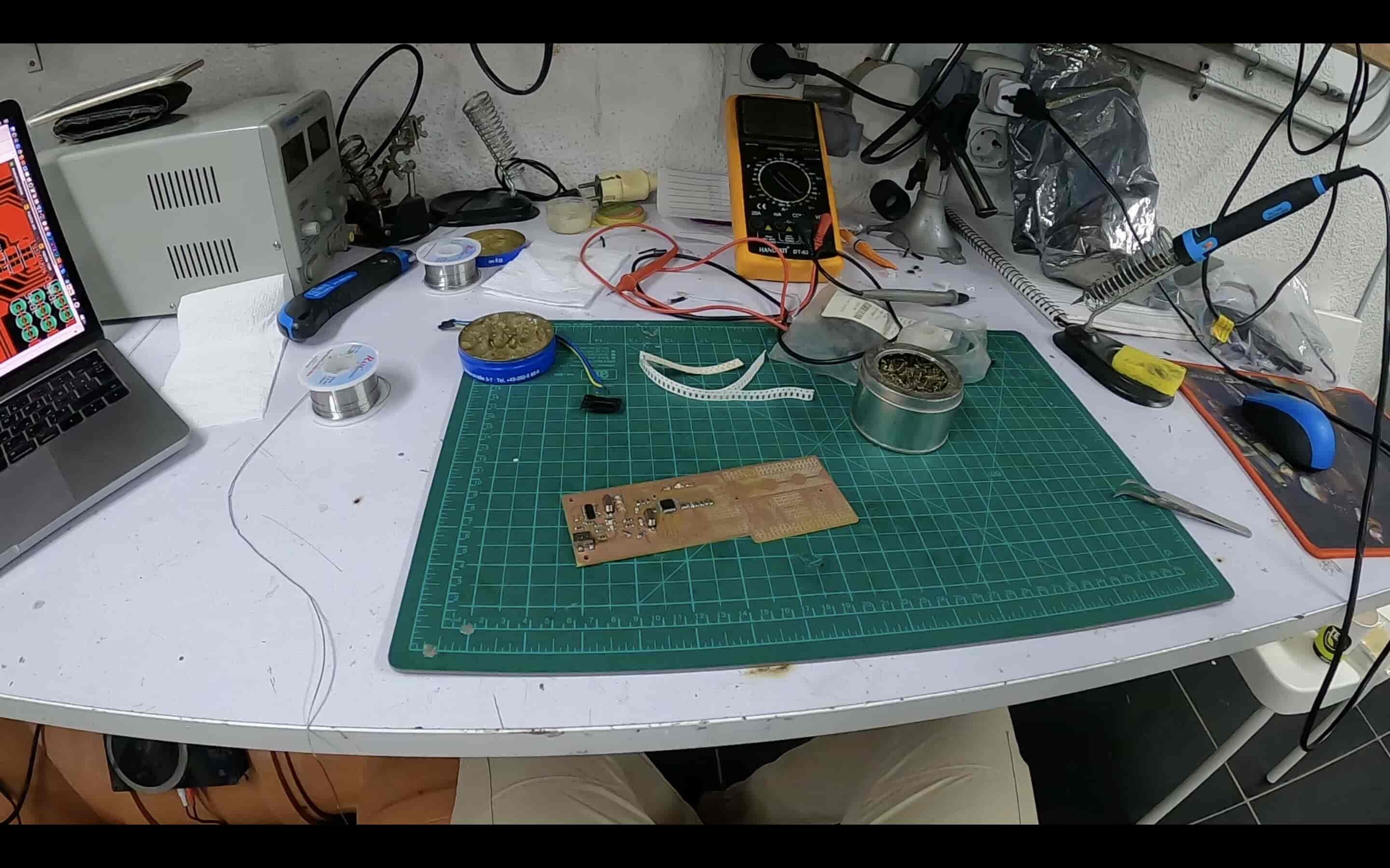
Now, it is time to do some soldering work. I prepared all the needed components from Fab Lab Egypt inventory. And did the soldering work.
| Part Number | Description | Quantity | Supplier |
|---|---|---|---|
| ATMEGA328P-AU-ND | IC MCU 8BIT 32KB FLASH 32TQFP | 1 | DigiKey |
| 2395958 | 16Mhz/18pF SMD 11.4 x 4.7 mm crystal | 1 | Farnell |
| 1898660 | 12Mhz/18pF SMD 11.4 x 4.65 mm crystal | 1 | Farnell |
| H2961CT-ND | CONN RECEPT MINI USB2.0 5POS | 1 | digikey |
| CH340G IC | CH340G | 1 | Ali Baba |
| 2984995 | SMD Multilayer Ceramic Capacitor, 22 pF, 10 V, 1206 | 4 | Farnell |
| 445-1423-1-ND | CAP CER 1UF 50V X7R 10% 1206- | 1 | DigiKey |
| 399-4674-1-ND | CAP CERAMIC .1UF 250V X7R 1206- | 4 | DigiKey |
| 587-1352-1-ND | CAP CER 10UF 35V Y5V 1206- | 2 | DigiKey |
| 311-10.0KFRCT-ND | RES 10.0K OHM 1-4W 1% 1206 SMD | 1 | DigiKey |
| 311-1.00KFRCT-ND | RES 1.00K OHM 1-4W 1% 1206 SMD- | 3 | DigiKey |
| 311-499FRCT-ND | RES 499 OHM 1-4W 1% 1206 SMD | 6 | DigiKey |
| 160-1169-1-ND | LED Green CLEAR 1206 SMD- | 3 | DigiKey |
| 160-1889-1-ND | LED Blue CLEAR 1206 SMD- | 3 | DigiKey |
| Male Through hole pin header | male Through hole pin header | 10 | AliBaba |
| Female Through hole pin header | Female Through hole pin header | 10 | AliBaba |
After finishing the soldering process, I prayed to allah that it works properly and to graduate this cycle :D
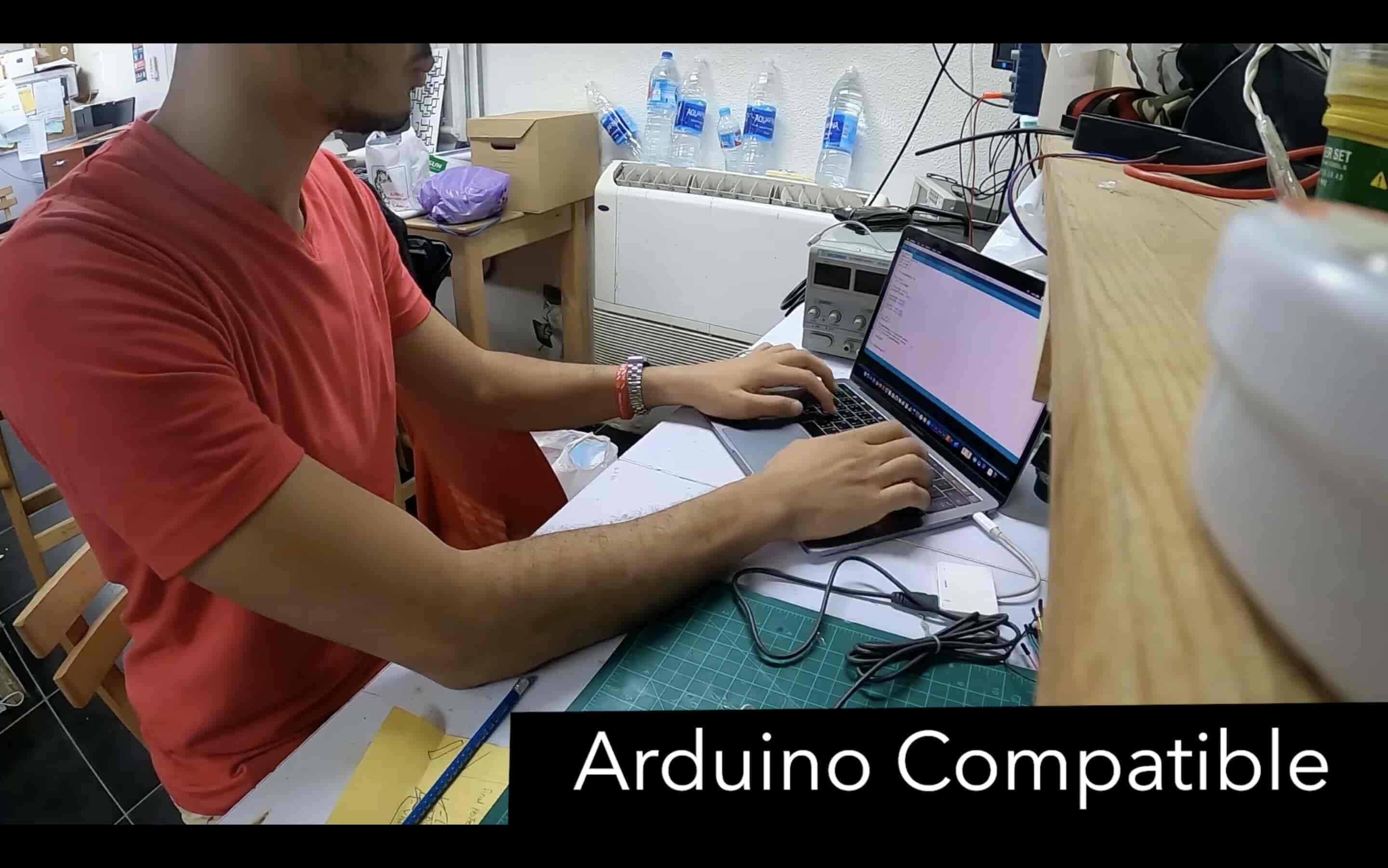
Uploading the Arduino UNO Bootloader To The Fab Breadboard PCB & The First Test
Since I wanna make the Fab breadboard a 100% Arduino UNO compatible, I uploaded the Arduino Uno bootloader to my ATmega328P-Au chip. I did that by connecting my AVR programmer that I made in the Electronics Production Week with the Fab Breadboard PCB through some jumper wires. See the table below.
| Fab Breadboard | USBtinyISP |
|---|---|
| VCC | 5V |
| GND | GND |
| D13 | SCK |
| D11 | MOSI |
| D12 | MISO |
| Reset | Reset |
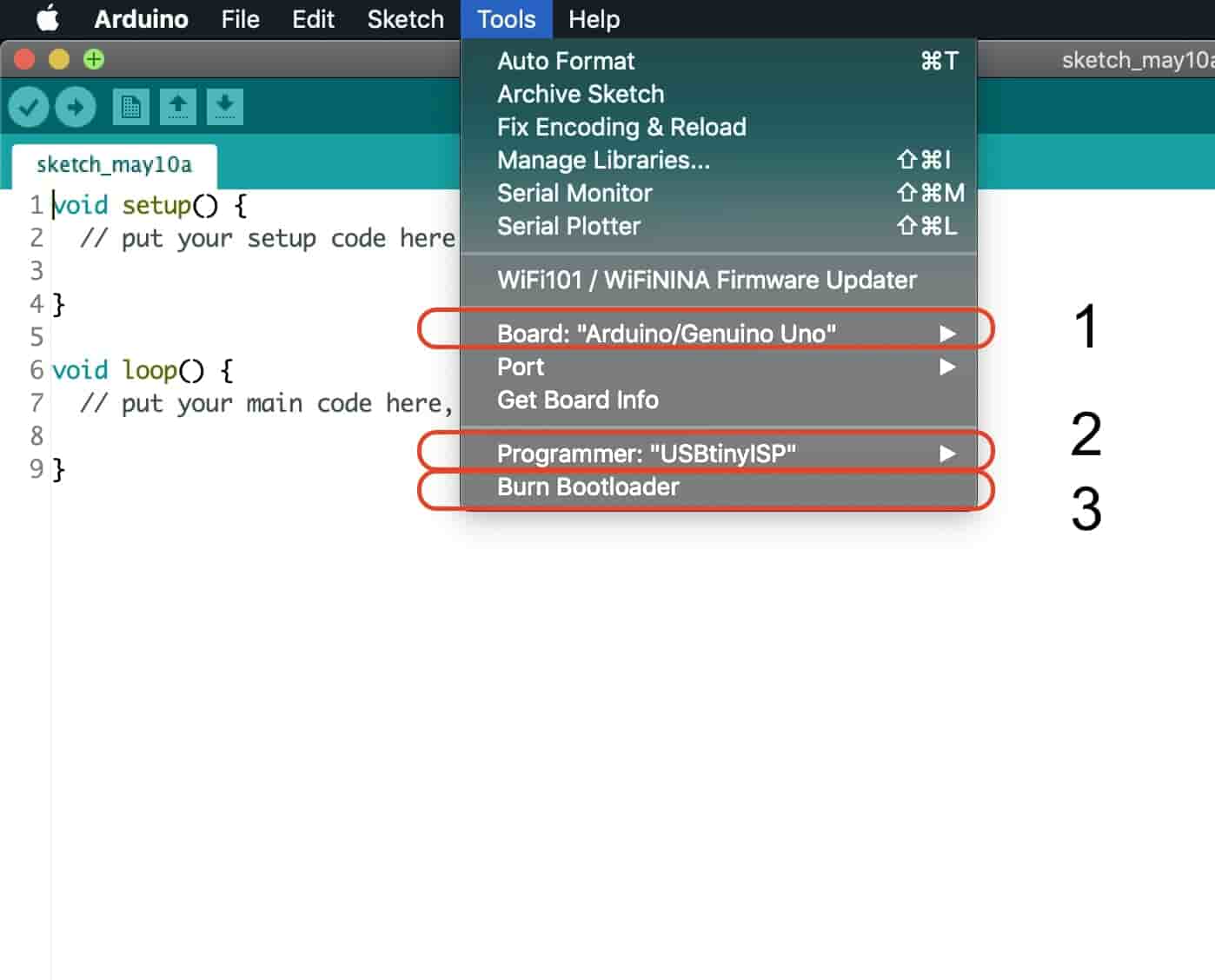
After that I opened Arduino IDE and burned the Arduino UNO bootloader to my ATmega328P-AU chip. I selected my board as “Arduino/Genuino UNO”, programmer as “USBtinyISP”, then I pressed “Burn bootloader”.
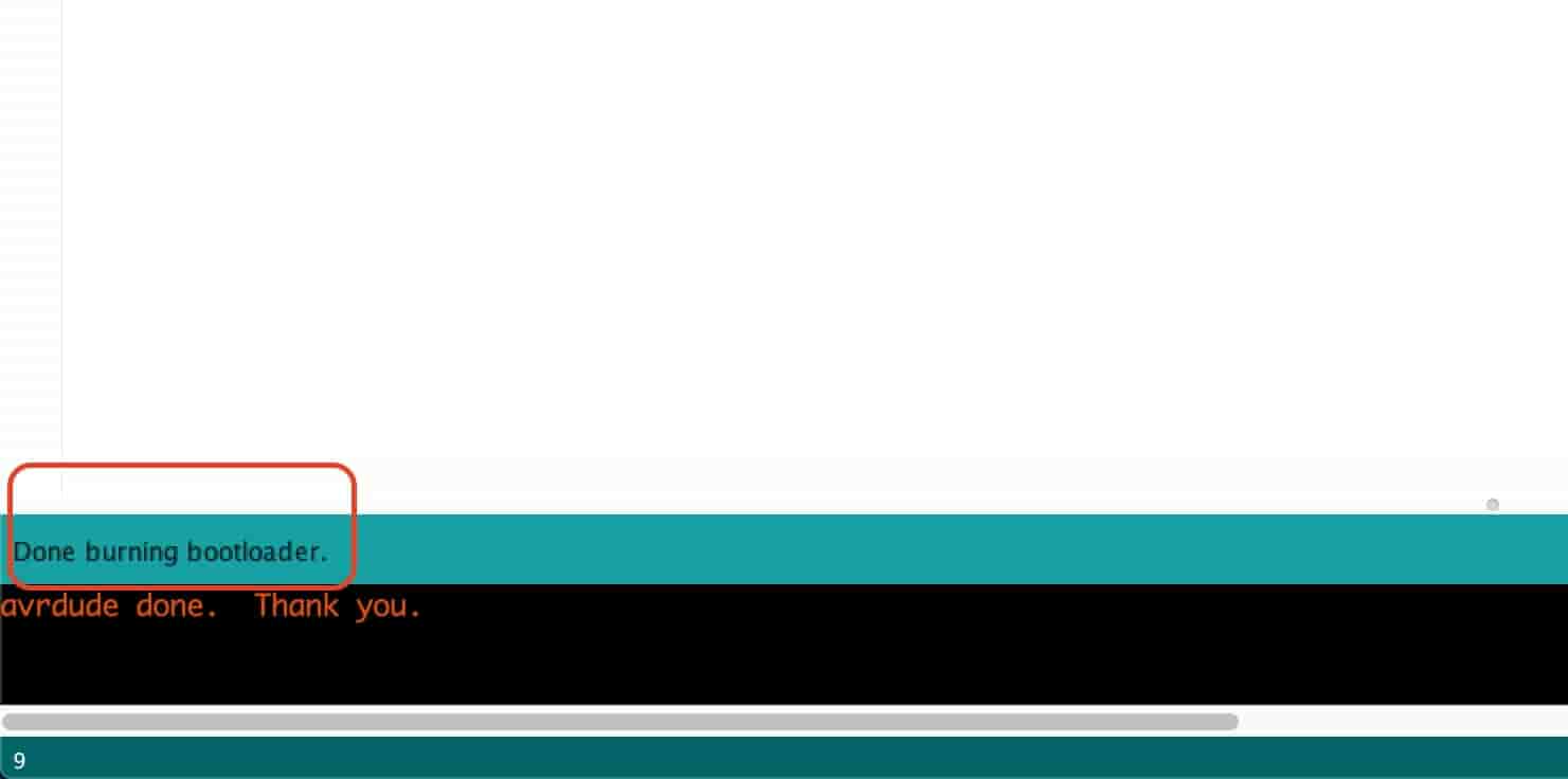
Once it said “Done Burning bootloader, now we are in the safe zone.
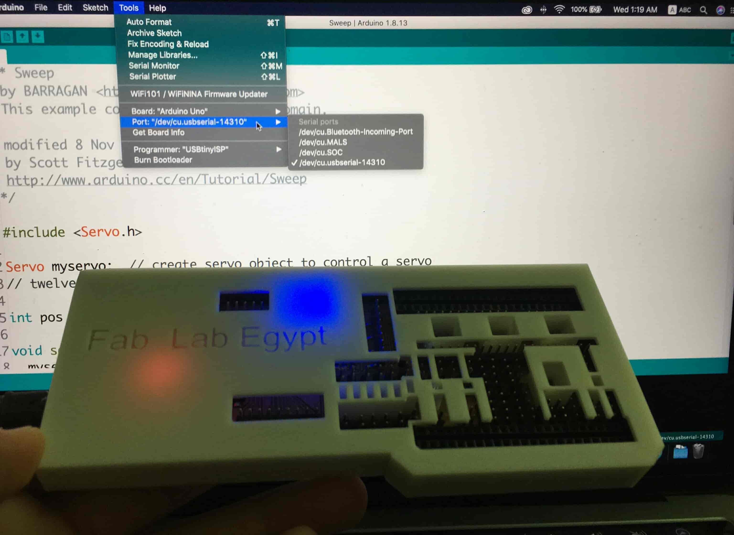
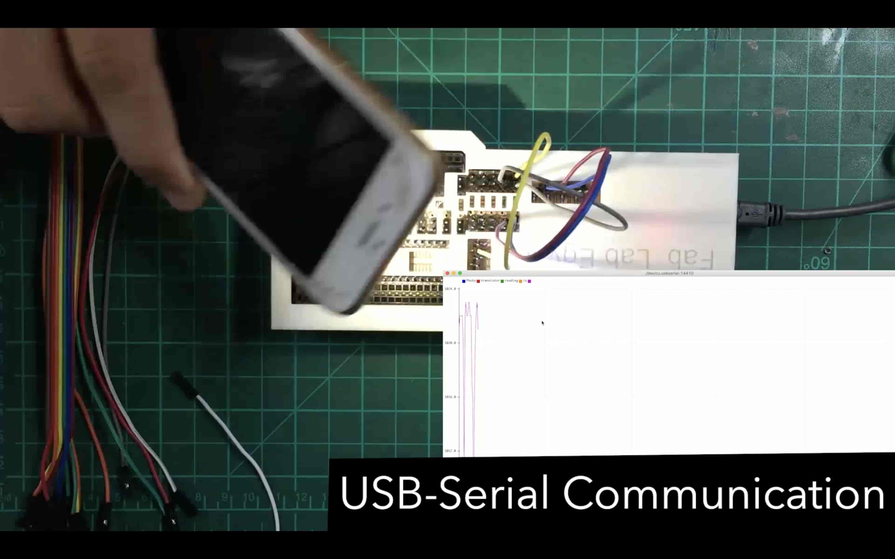
I wanna make sure that the CH340G circuit is working correctly and the computer is recognizing my board and transmitting/receiving data. I connected my board to my laptop through the USB cable and guess what! It's working, baby.
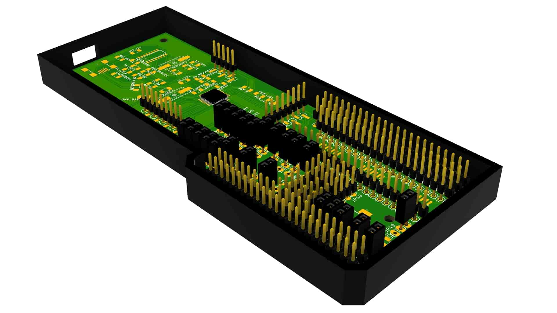
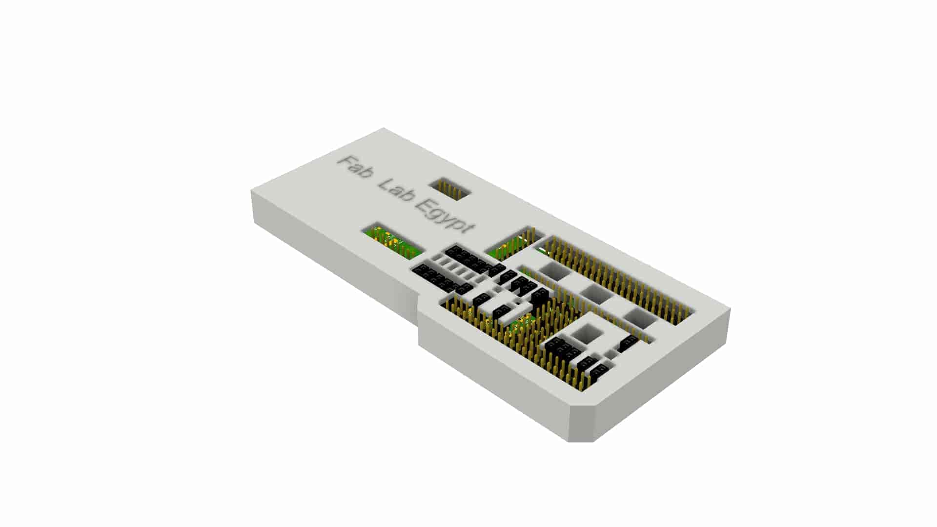
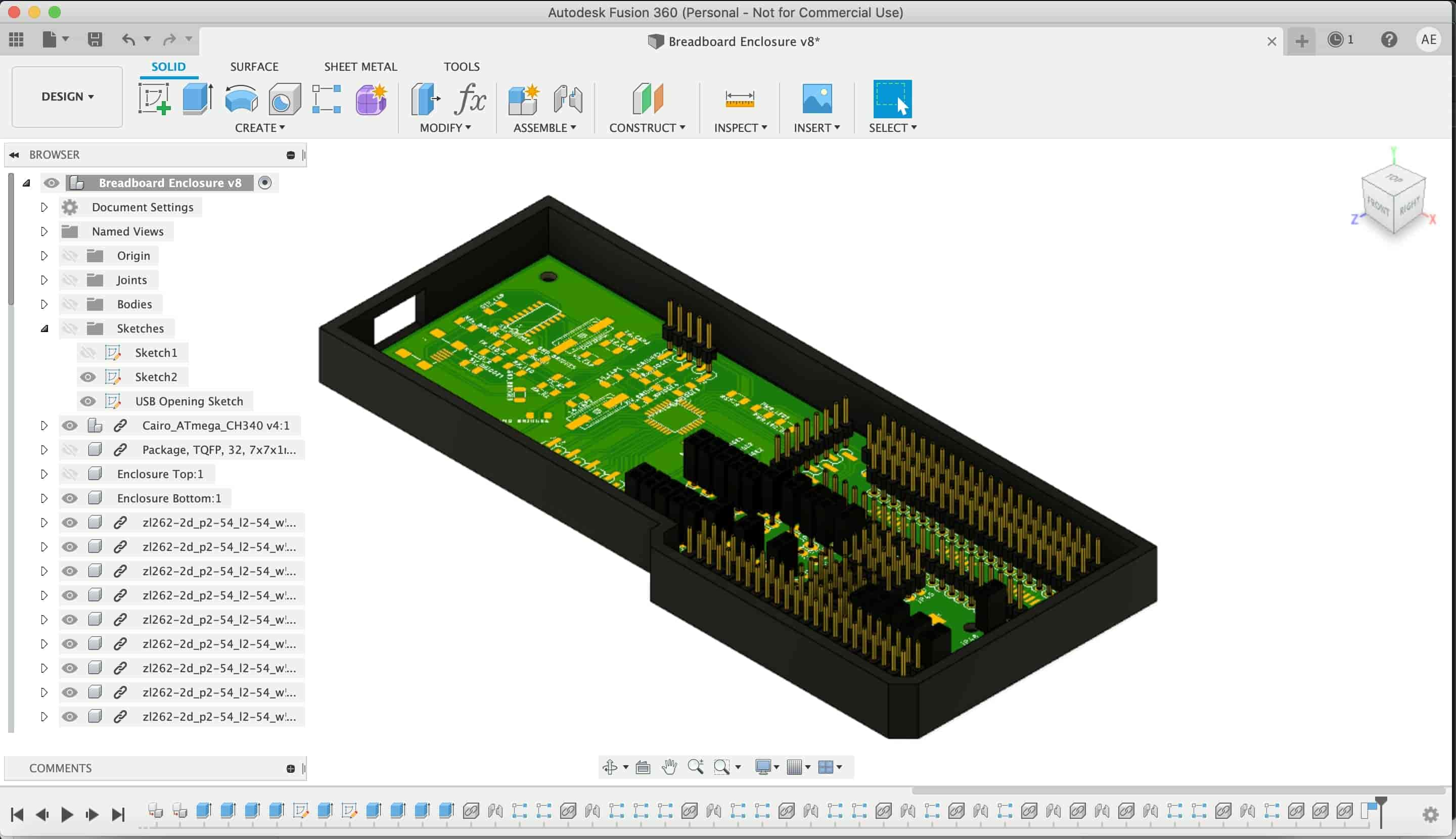
The Fab Breadboard Enclosure Design And Fabrication
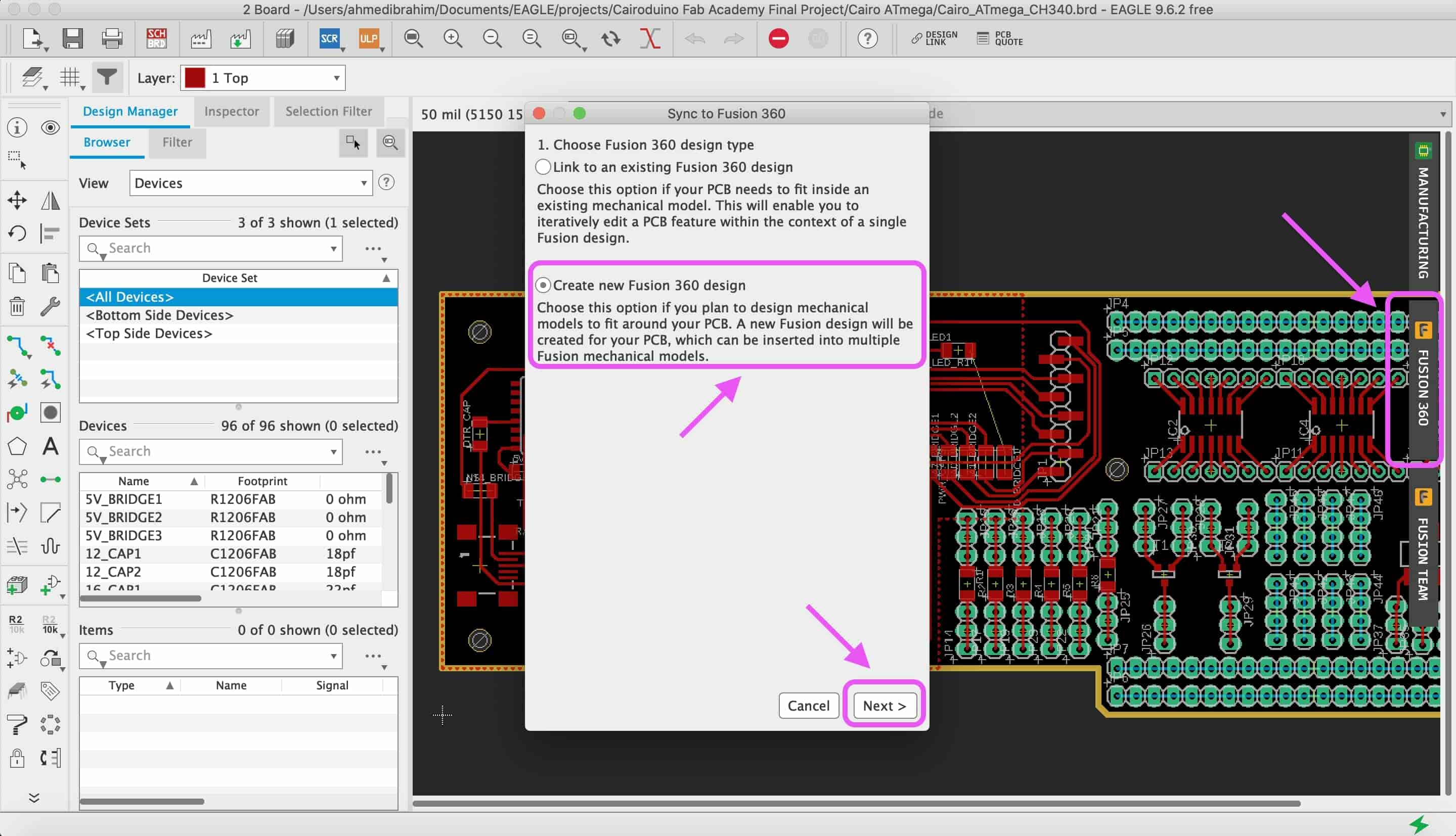
After making sure that everything is working fine and we will not need to change the PCB dimensions, let’s start designing the Fab breadboard enclosure that will play a very important rule in our project. It’s not only to make the project look nice. But, the main rule is to keep the tiny SMD components in-place and not to fall down or something. To design the Fab Breadboard enclosure, I used Fusion360. I imported the Fab Breadboard PCB project from Eagle to Fusion360. If you wanna know more details about how to do that, check out the step “Designing An AVR Programmer Enclosure” in the 3D scanning and printing Week .
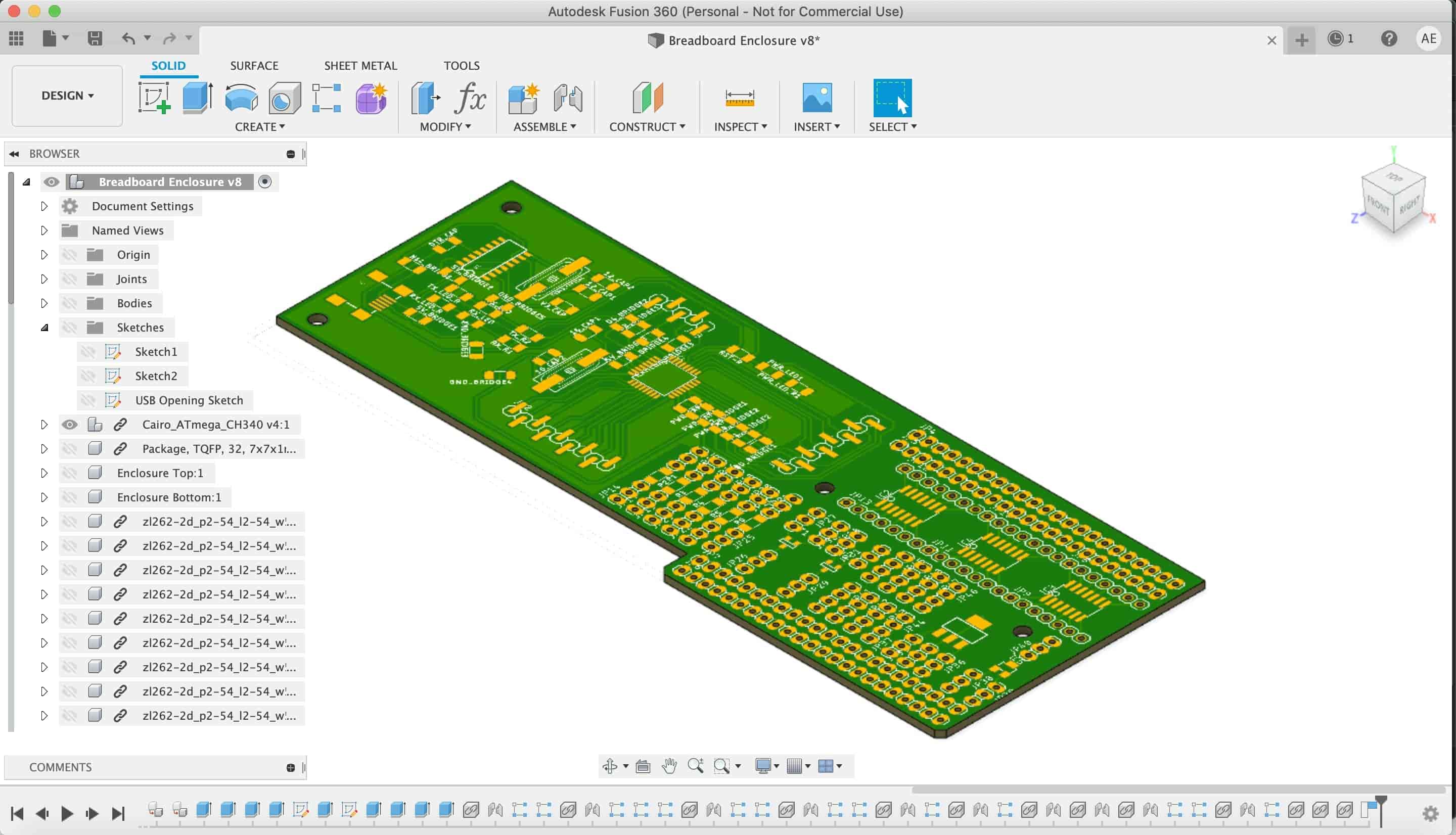
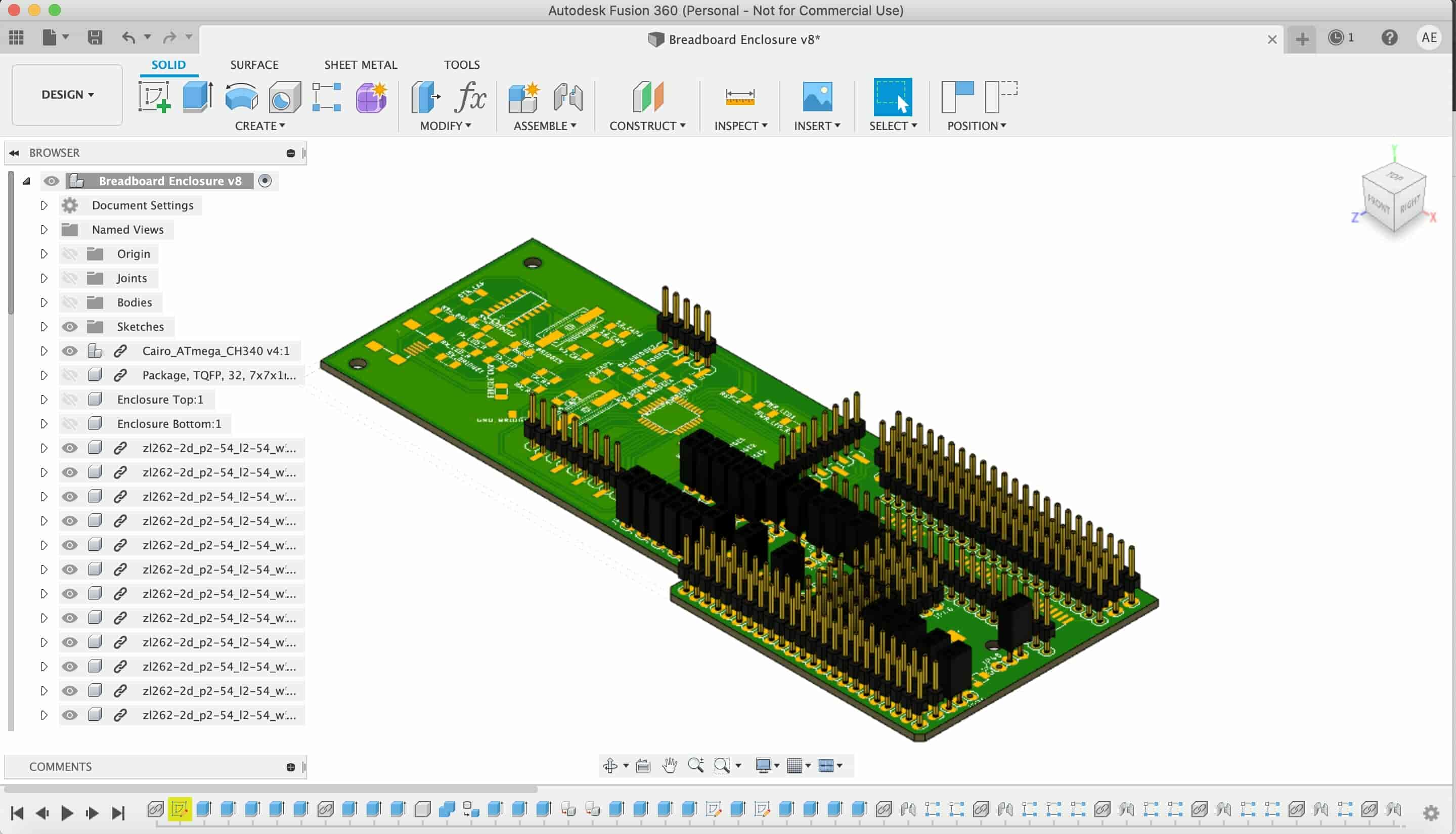
After that I imported and joined the main pin headers on the PCB to decide how much is the height of the enclosure,
After that I started drawing the top and bottom parts of the enclosure.
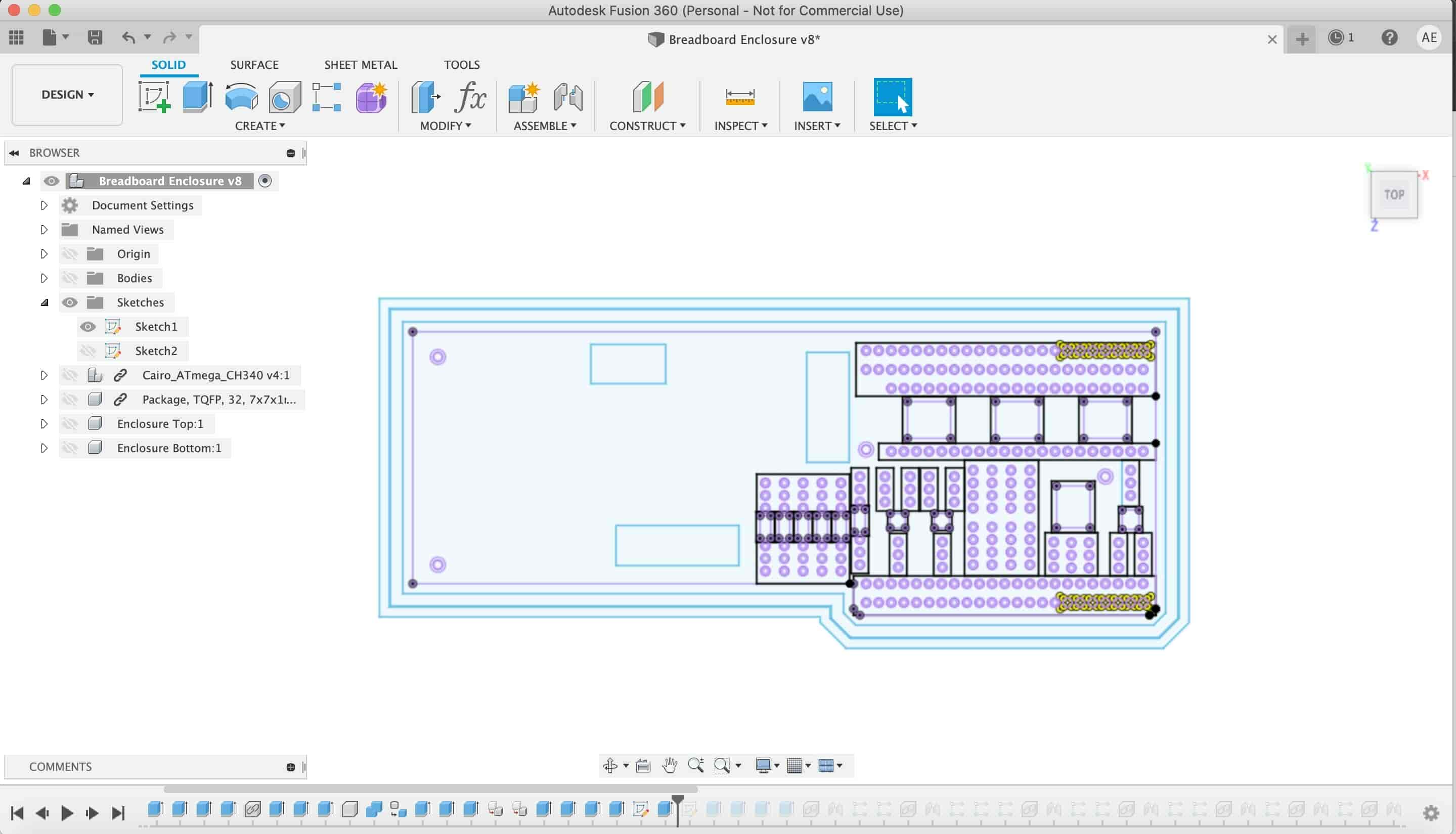
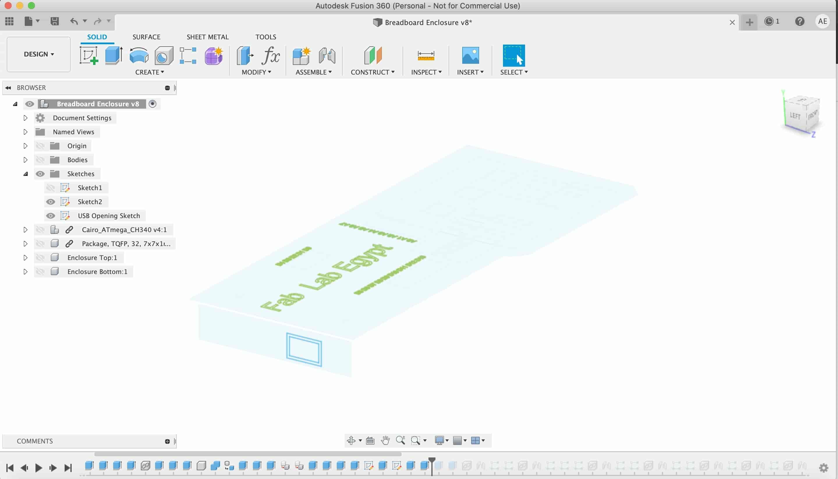
On the top part of the enclosure there are openings for all the SMD packages to slide in and stay in place.
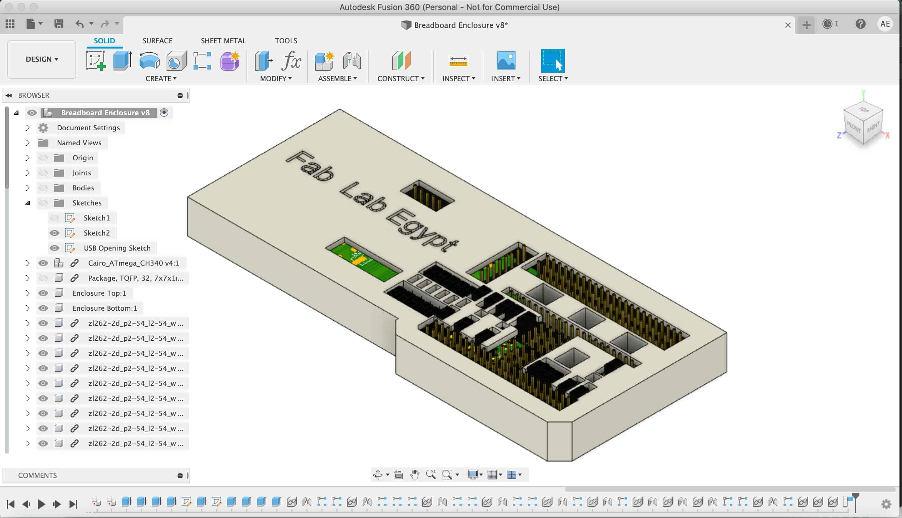
Also, there are opening for the Arduino GPIO pins.
And, on the bottom part of the enclosure there is an opening for the USB connector.
Enclosure STL Files Download
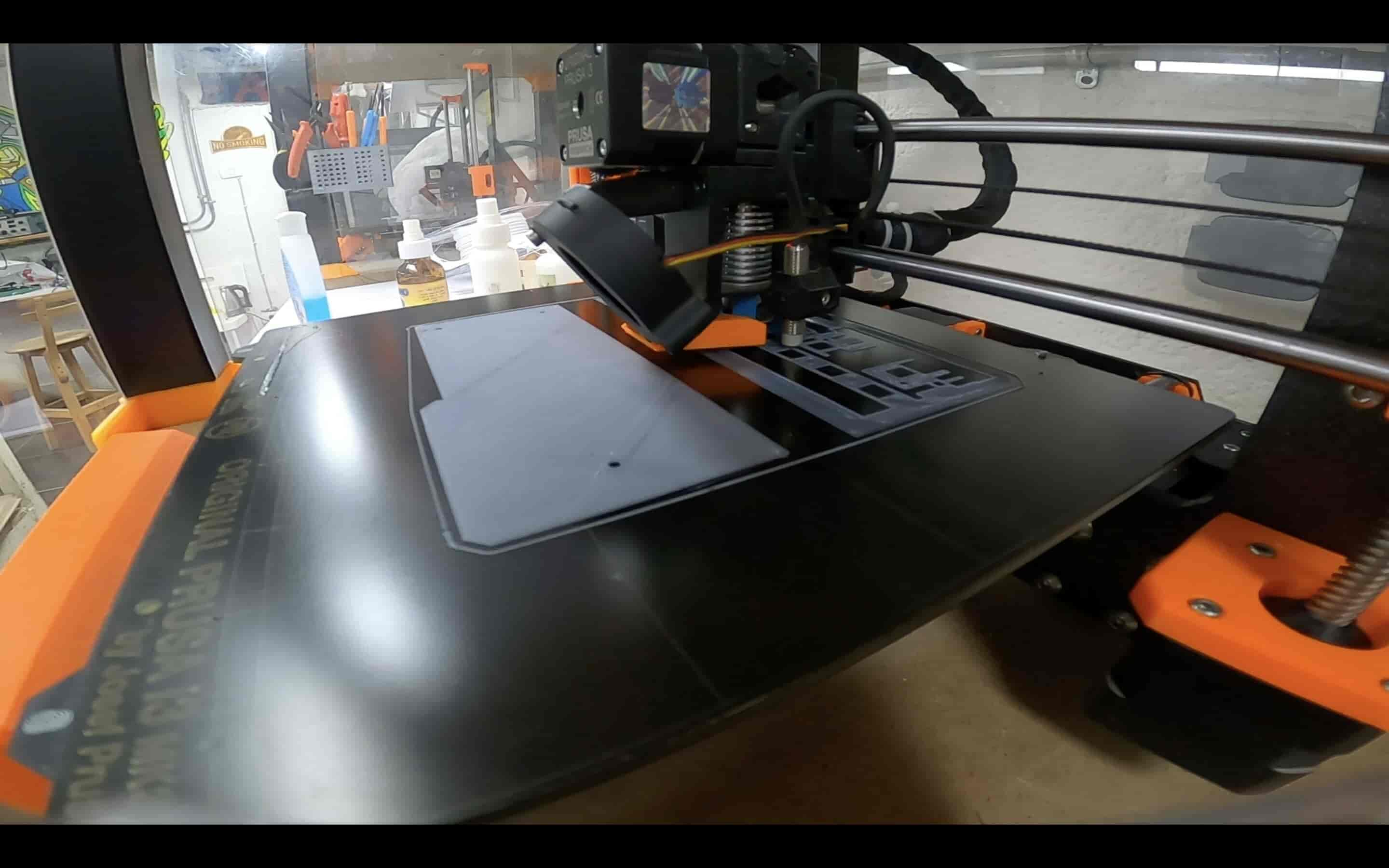
Now lets start the fabrication process. I used the awesome Prusa 3D printer that we have in Fab Lab Egypt to print the Fab Breadboard enclosure. I imported the STL files into Cura and set the printing parameters. I set the infil to 20%, retraction distance 0.8mm, layer height 0.2mm, and no supports. Then I sliced the model, the printing duration is around 6 hours.
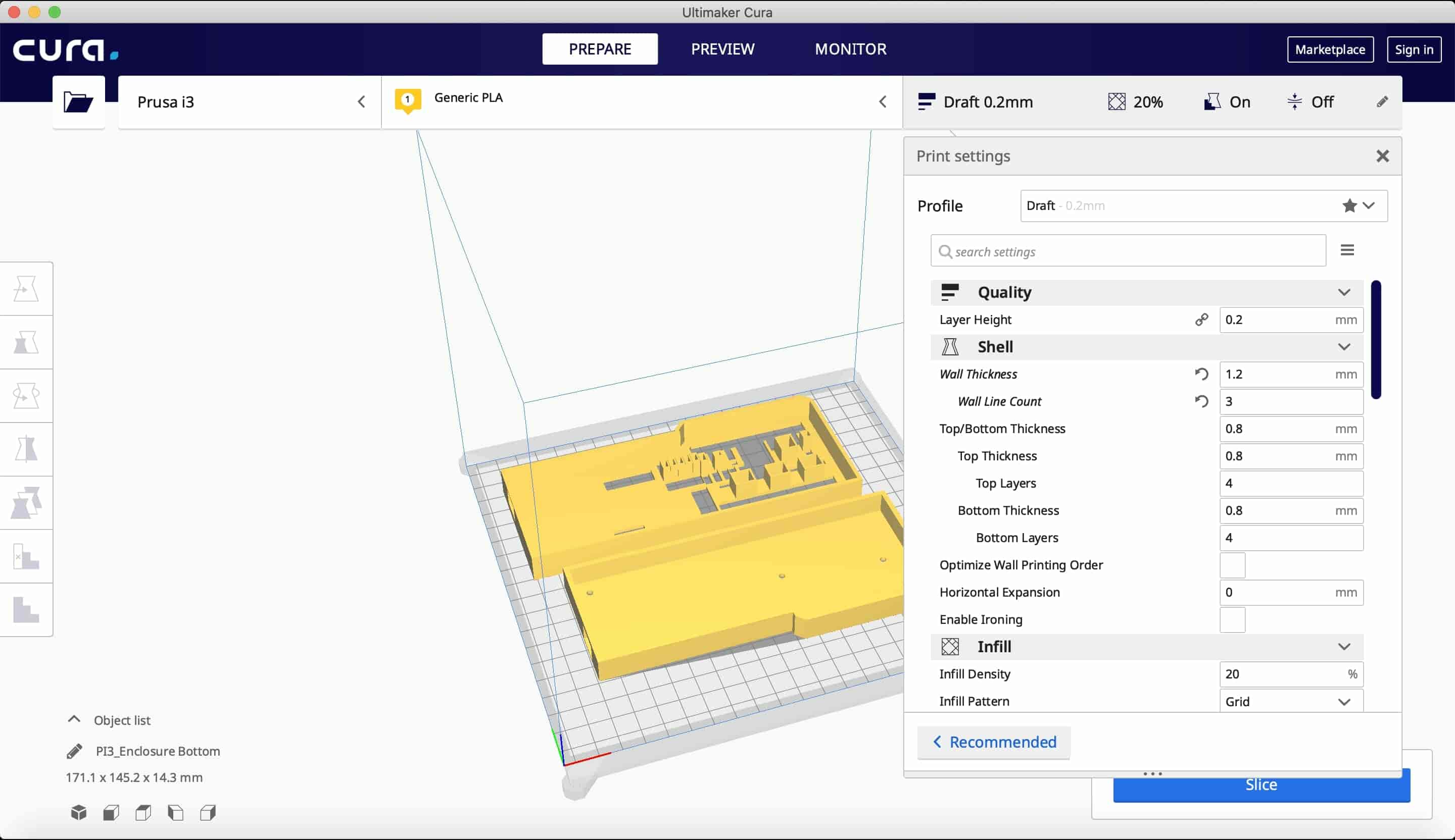
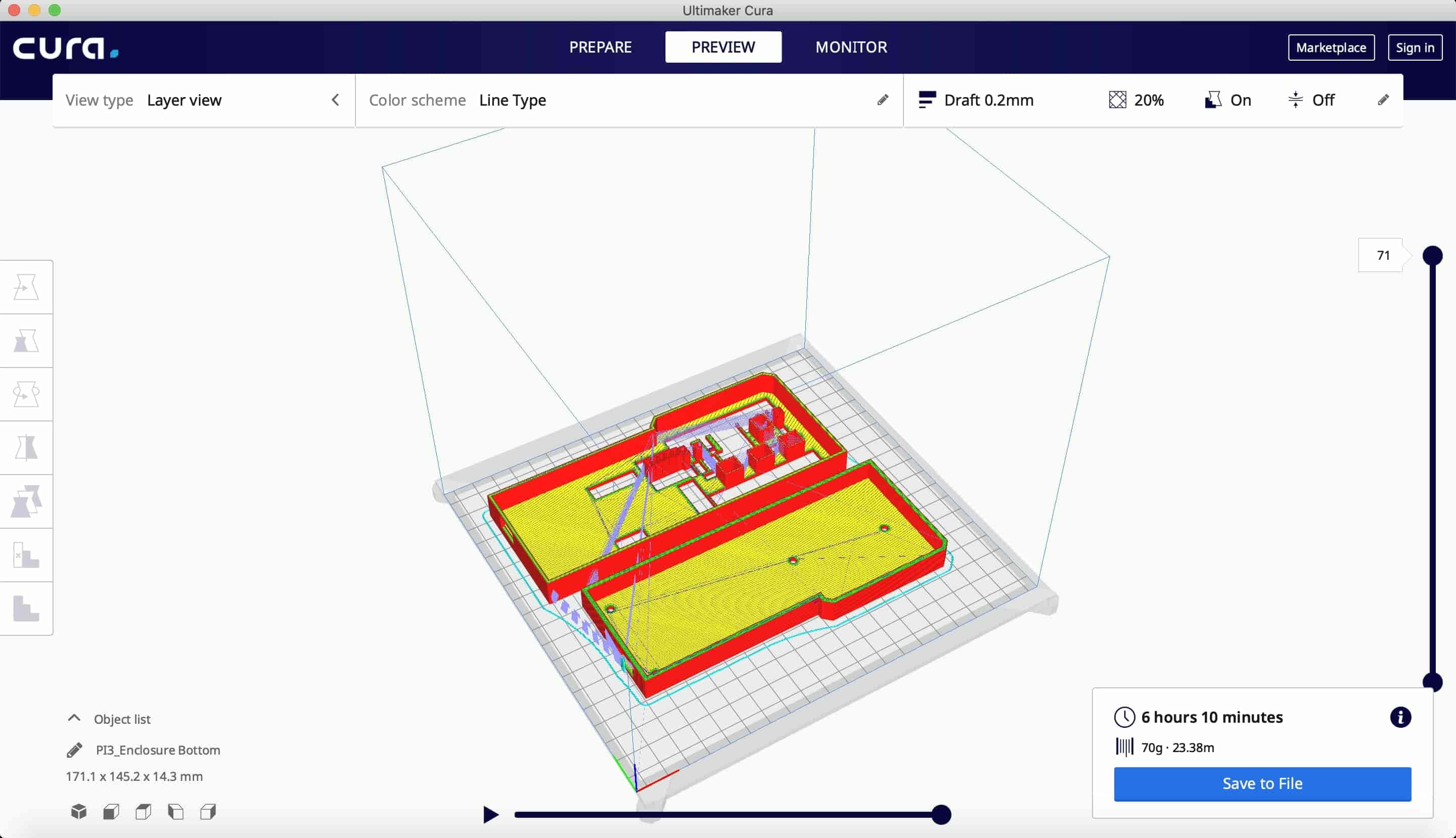
Then I exported the Gcode file to the Prusa’s memory card and started printing.

Testing And Getting Things To Work
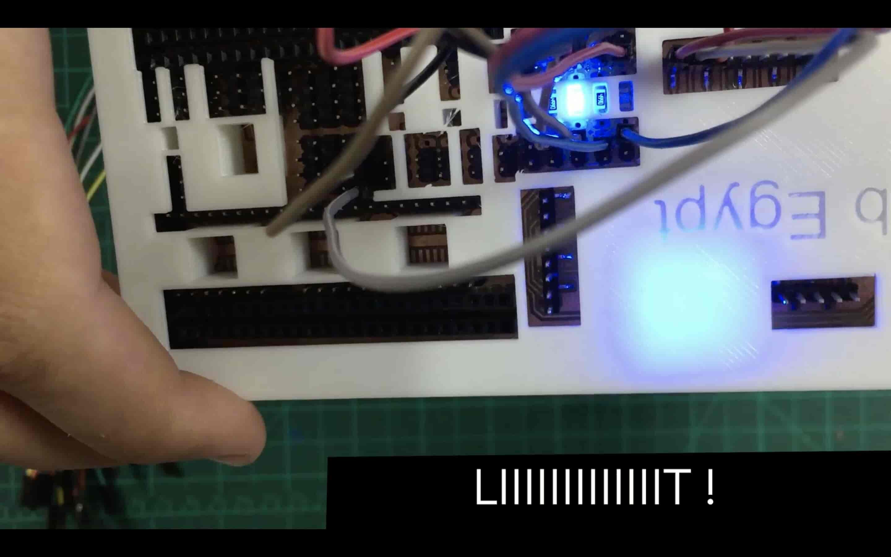
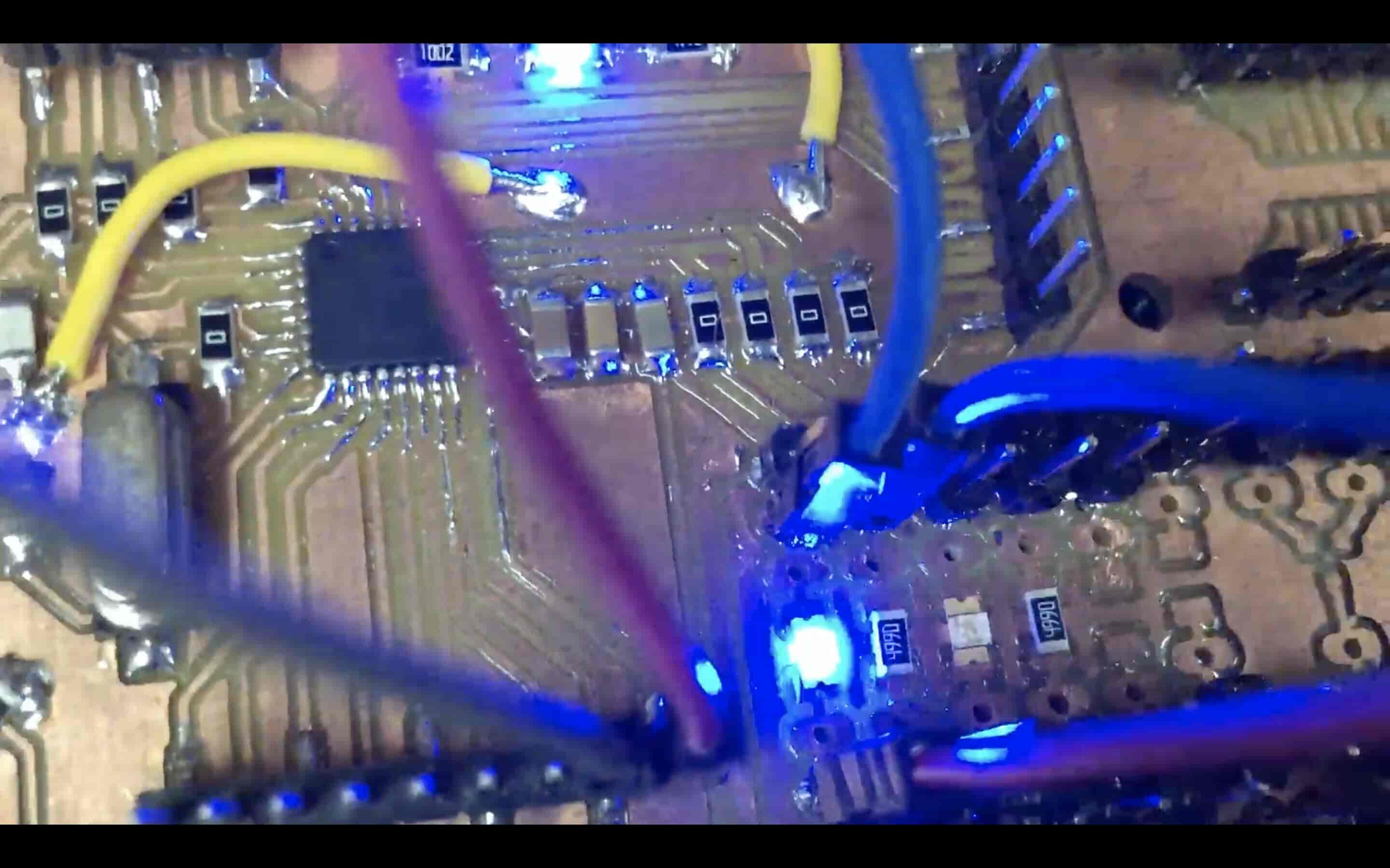
I wanna test the Fab Breadboard and see if things work fine together or not. I put a phototransistor on the 1206 package placed on the fab breadboard(of course without any soldering). and I wrote a simple code that reads the sensor data and display it on the Serial monitor. And it worked so good without any problems.
#define firstLED 8#define PT_sensor A1
#define LED 13
#define GND 12
#define VCC 11

int PT_sensorReading = 0;

void setup() {
  Serial.begin(9600);

  pinMode(LED, OUTPUT);
  pinMode(PT_sensor, INPUT);

  pinMode(GND, OUTPUT);
  pinMode(VCC, OUTPUT);

  digitalWrite(GND, LOW);
  digitalWrite(VCC, HIGH);
}

void loop() {
  blinking();

  PT_sensorReading = analogRead(PT_sensor);
  Serial.print("Photo transistor reading is:    ");
  Serial.println(PT_sensorReading);

  //delay(50);
}


void blinking() {
  digitalWrite(LED, HIGH);
  delay(1000);
  digitalWrite(LED, LOW);
  delay(1000);
}
Also, I tried a 1206 package LED. I placed it in the 1206 package place on the fab breadboard(again, without any soldering). And, it worked smoothly. Note that I used the D12 pin as a GND pin for the LED.
void setup() {

    pinMode(13, OUTPUT);
    pinMode(12, OUTPUT);

    digitalWrite(12, LOW);

  }

  void loop() {
    digitalWrite(13, HIGH);
    delay(1000);
    digitalWrite(13, LOW);
    delay(1000);
  }
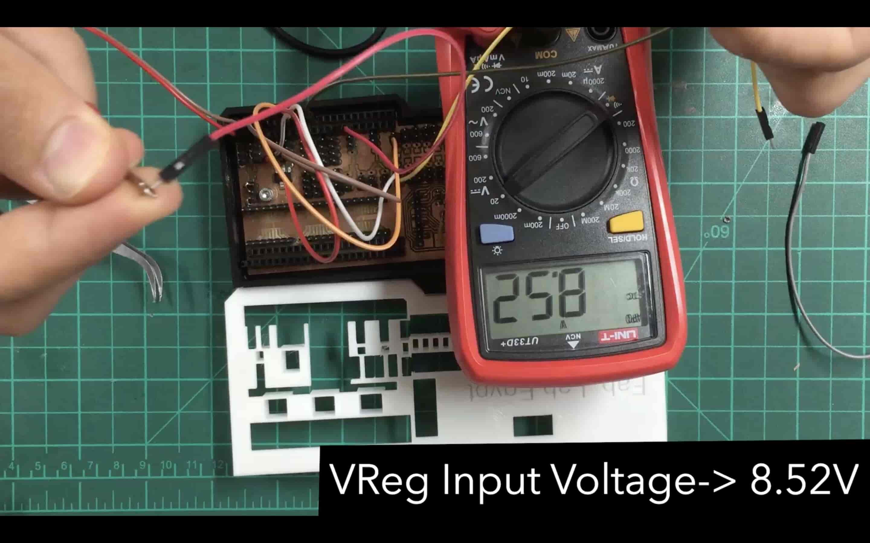
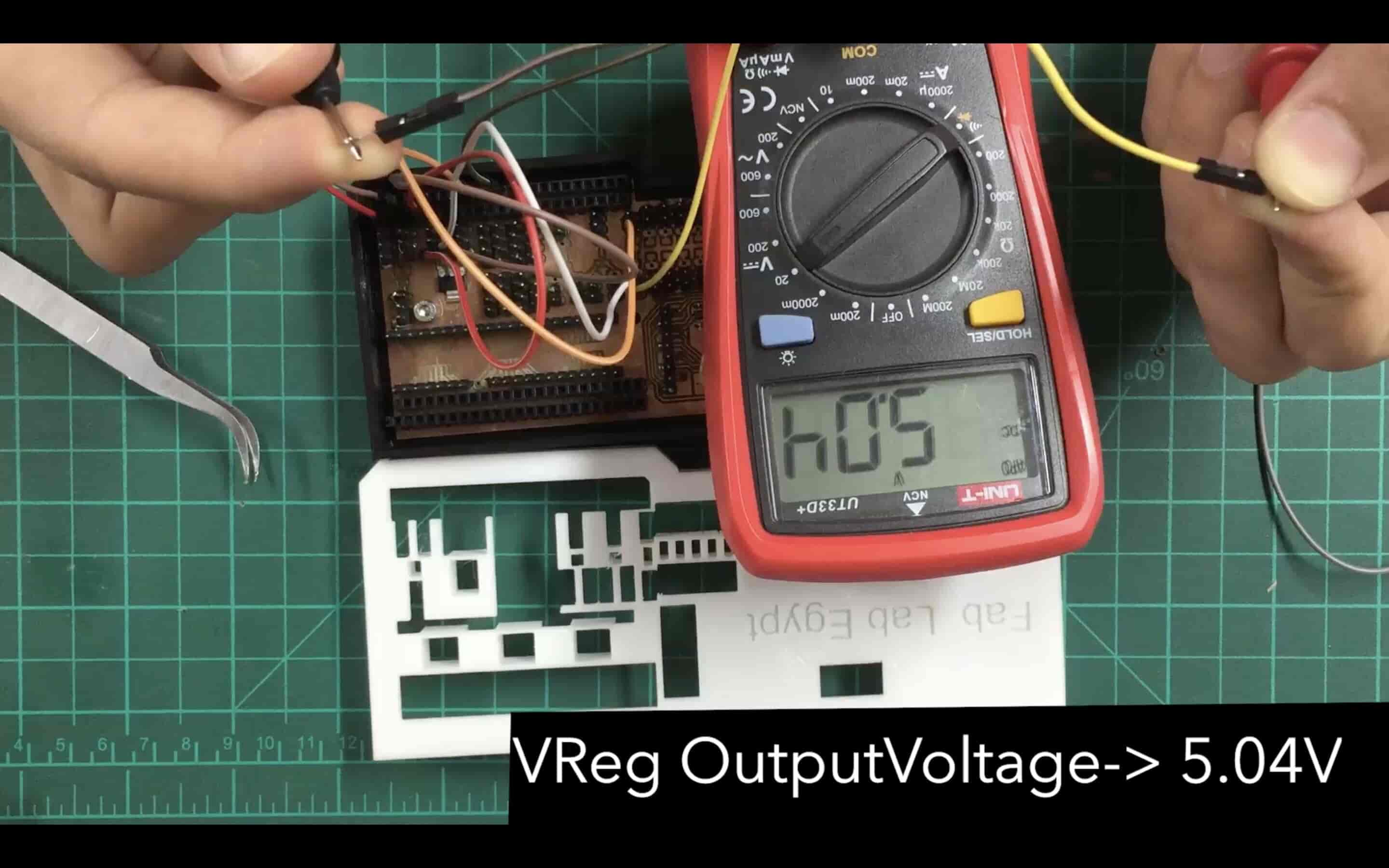
Also, I tried to test a 5V voltage regulator. I placed the voltage regulator above it’s pads without any soldering. And I tested the input and output voltage and it’s working smoothly too.
Finalizing The Work
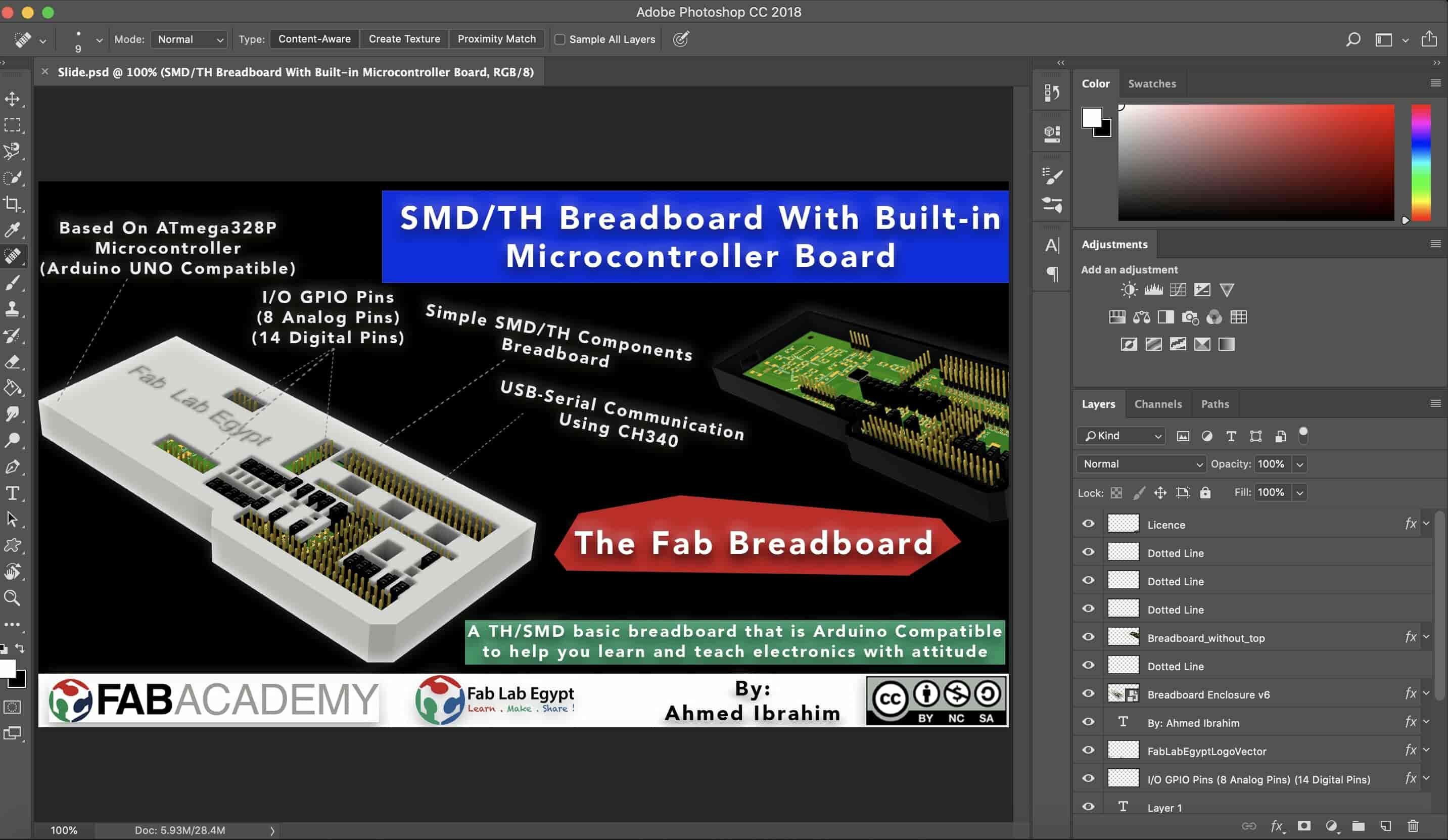
To make things look cool, let’s do some designing and video editing stuff. I started with the poster designing. I used to do some photo editing and retouching work with photoshop for clients many years ago. I guess, it's time to get my hands dirty again! I exported a rendered image from fusion360 and imported it into photoshop. And started adding texts, samples, changing background color, adding some light effects, and so on and it ended up with this sickass image.
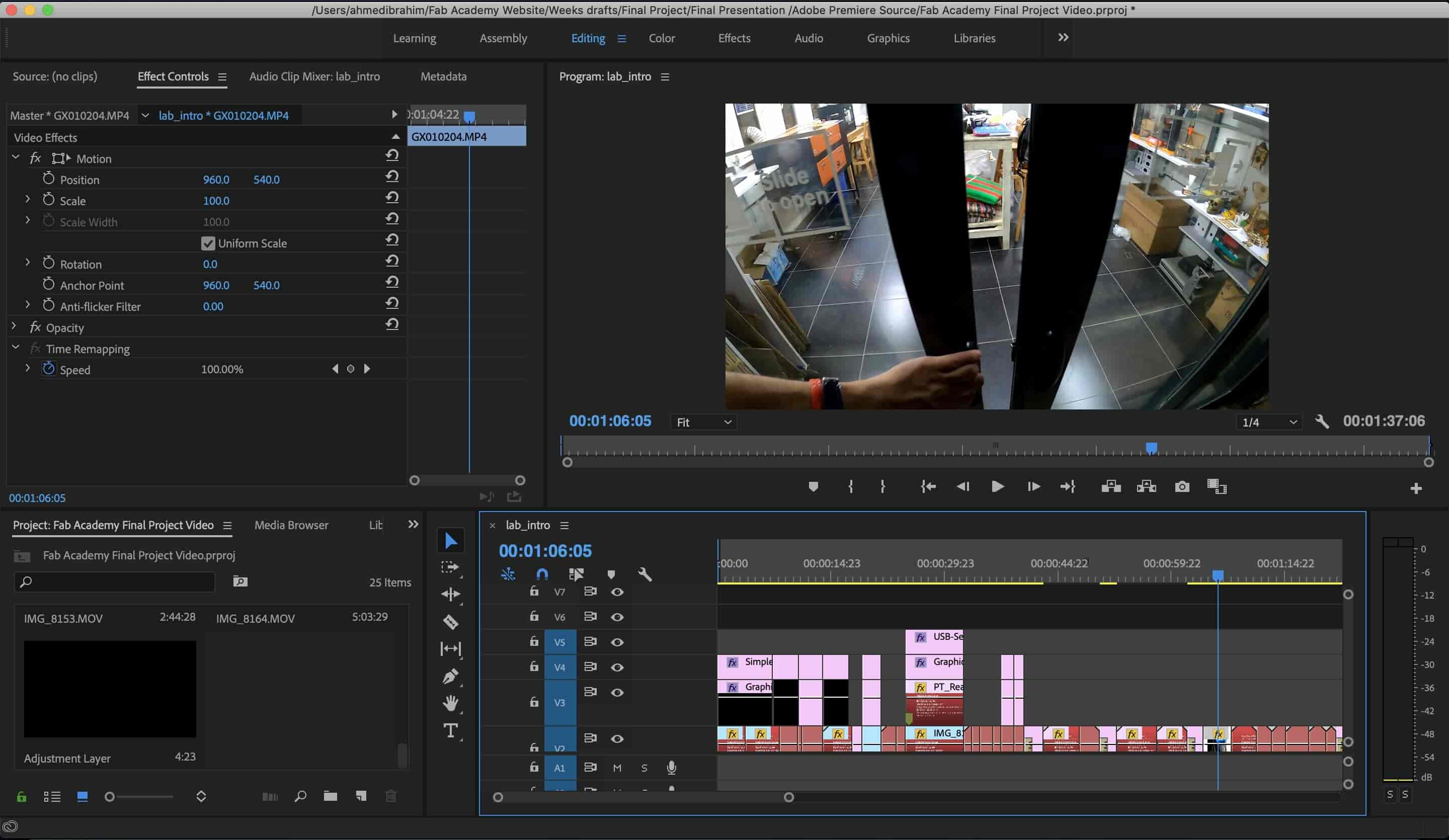
Let’s work on the final presentation video. Guess what! 3-4 years ago I used to do some montage and video editing work for underground rappers here in Egypt on Adobe Premiere(check out my old work, this too, this too). Let’s do it again on Adobe premiere. I opened it and started to add my videos and choosing the best clips from them to make an attractive not boring 1 minute video.
Fab Breadboard by Ahmed Ibrahim is licensed under a Creative Commons Attribution-ShareAlike 4.0 International License.