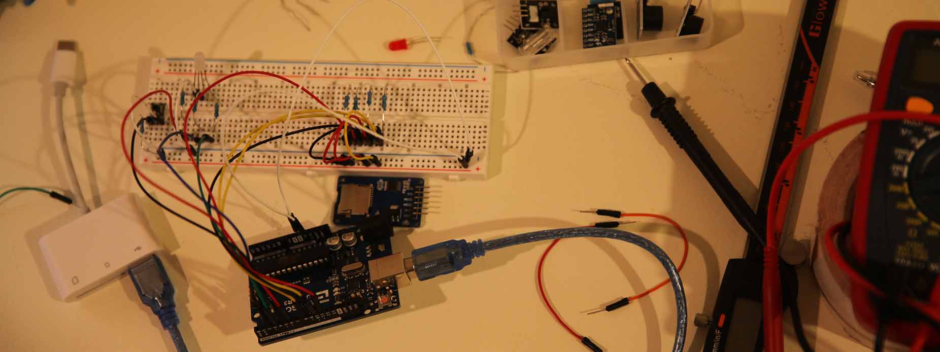
This week we were in about week three of shelter in place. It's pretty tough to not be able to leave the house... kind of driving everyone insane. This week I explore with Tinkercas circuits and tried to focus on working with LEDs and RGB LEDs since my actual output in my realy final project is going to be neopixels. This is very different than working with neopixels but I think the experience I'm getting this week is really more foundational level work with Arduino IDE and also with understanding simple output devices and how to code for them. All in all, it was a pretty good week and I'm hoping I can implement what I've learned for my final project.
Notes from Greg's Lesson
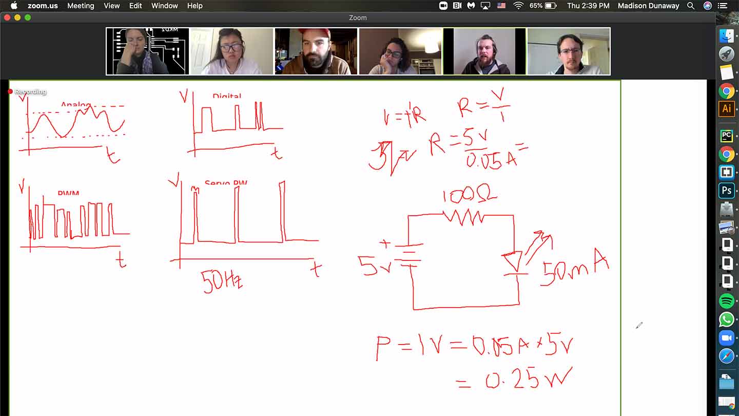
I'm at the far left... I can't remember if I was blinking or nodding off... but I did learn about Pulse Width Modulation and the equation that helps us measure the power consumption of an putput device. Power = current x voltage.
A few things are becoming more clear... I need to be able to properly use a multimeter, I need to learn how to understand Arduino code, and I need to become more fluent in basic electronics.
Multimeter Slideshow (press arrow)
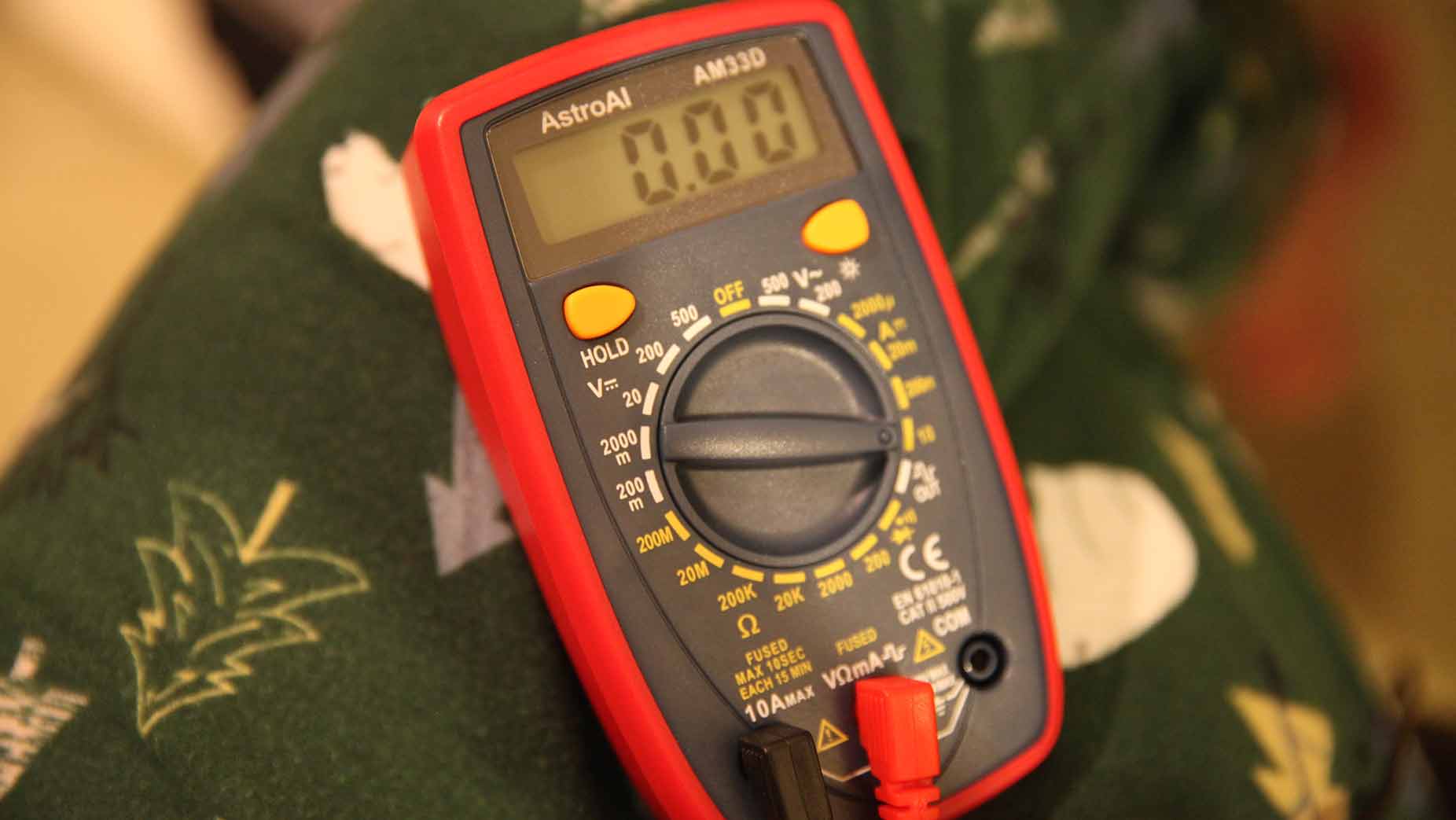
What is a multimeter?
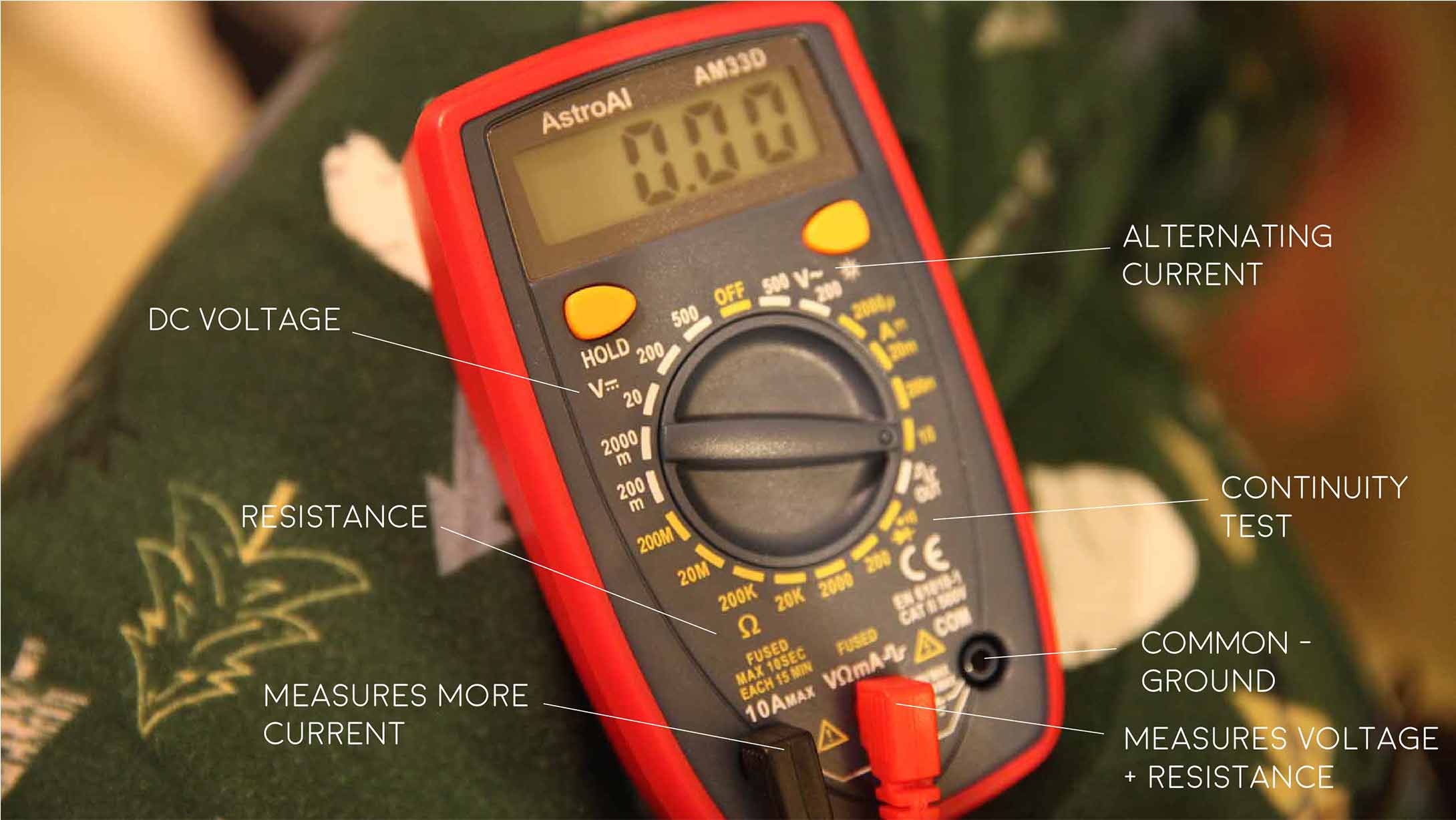
This handout from Sparkfun was very helpful and explains that a multimeter is a helpful tool when it comes to troubleshooting circuits.
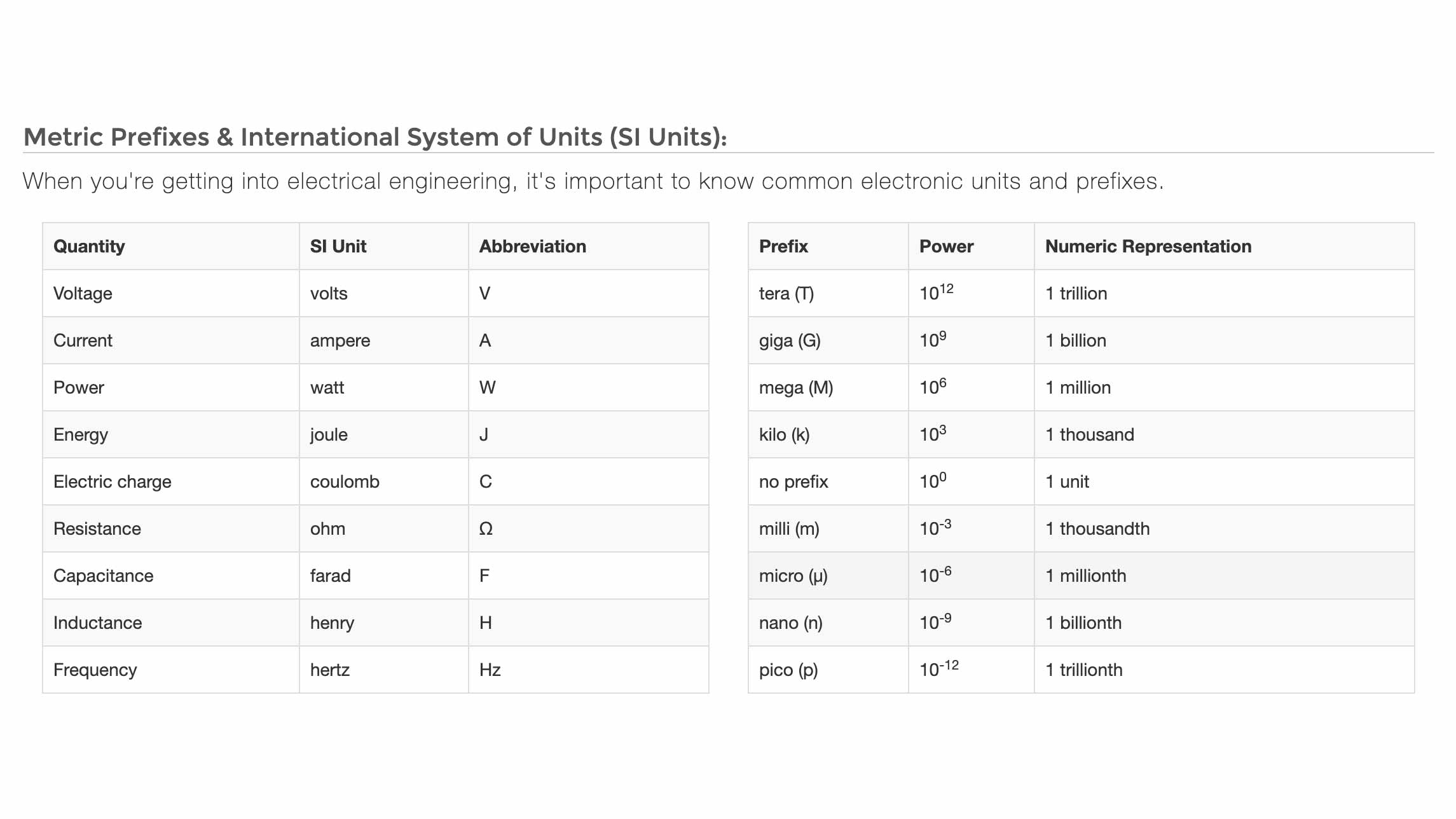
Knowing the prefixes helps...
This is another great page on Sparkfun that goes over Metric Prefixes and SI Units.
What's what
This is my multimeter and a few buttons/symbols I learned about.
Testing out on Tinkercad
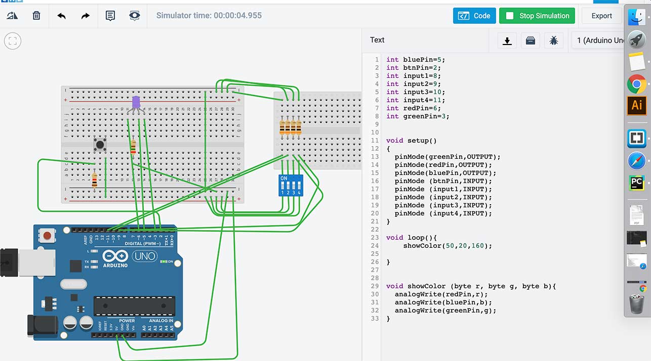
This was my original idea to get started with.
I then realized I didn't have any switches like that one so I thought I could just unplug the jumper wires until I can get the real thing.
IRL
| Pin 2: Button | Pin 11: "Switch 1" | |
|---|---|---|
| Pin 3: Blue | Pin 10: "Switch 2" | |
| Pin 6: Red | Pin 9: "Switch 3" | |
| Pin 5: Green | Pin 8: "Switch 4" | |
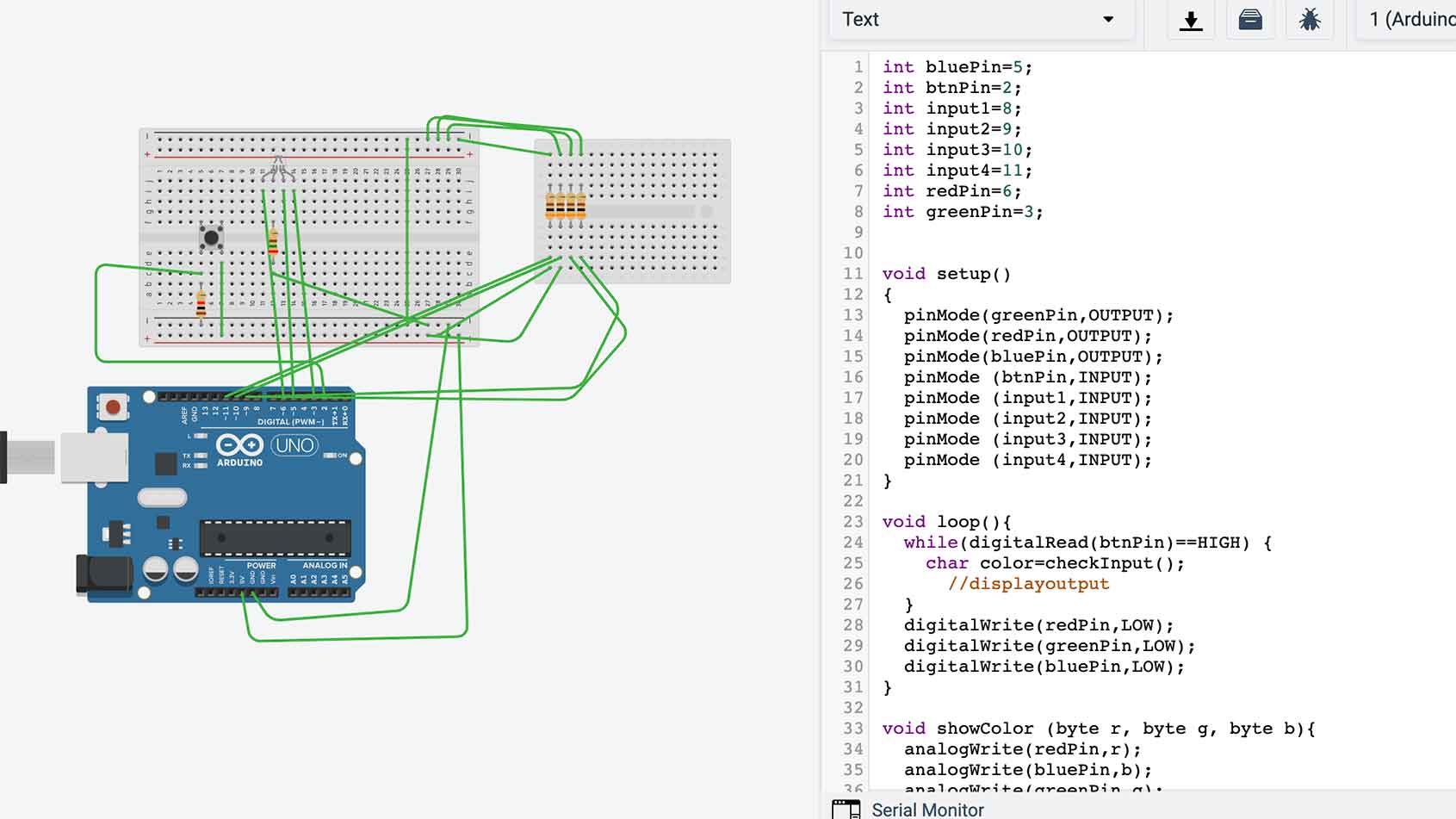
Obviously I had to tweak my tinkercad "schematic" quite a bit... but then I kinda got it working!
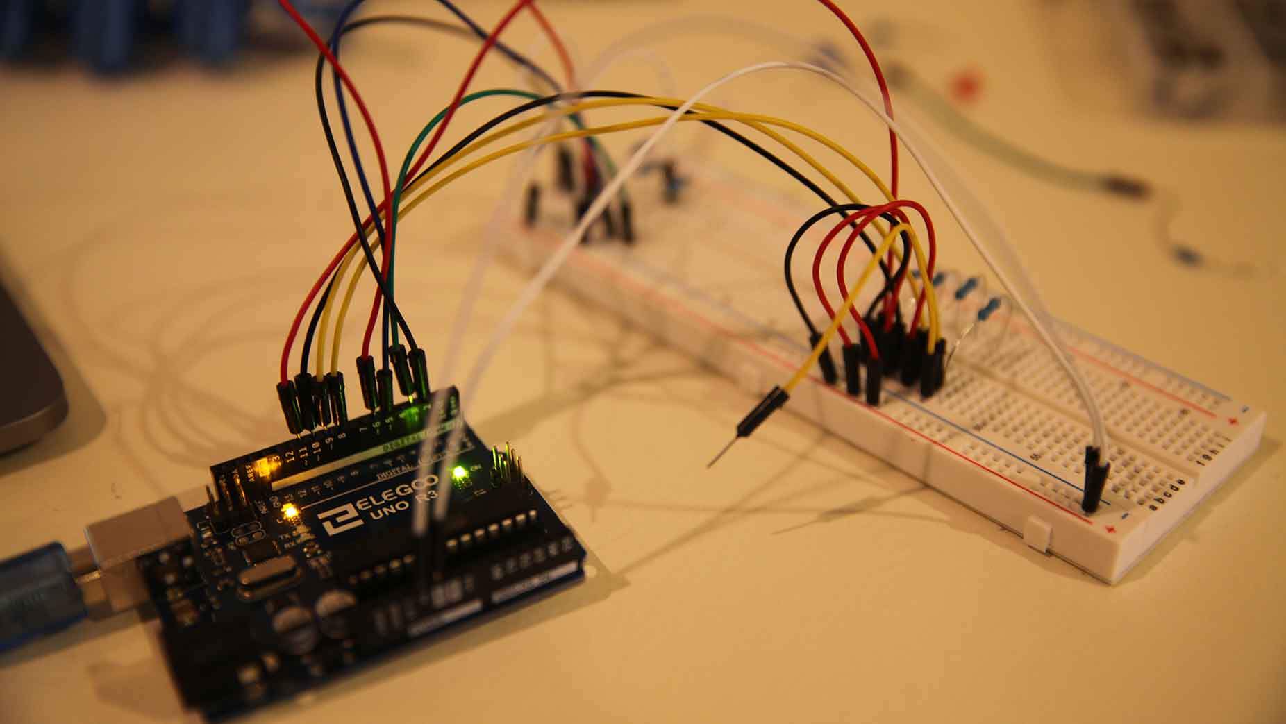
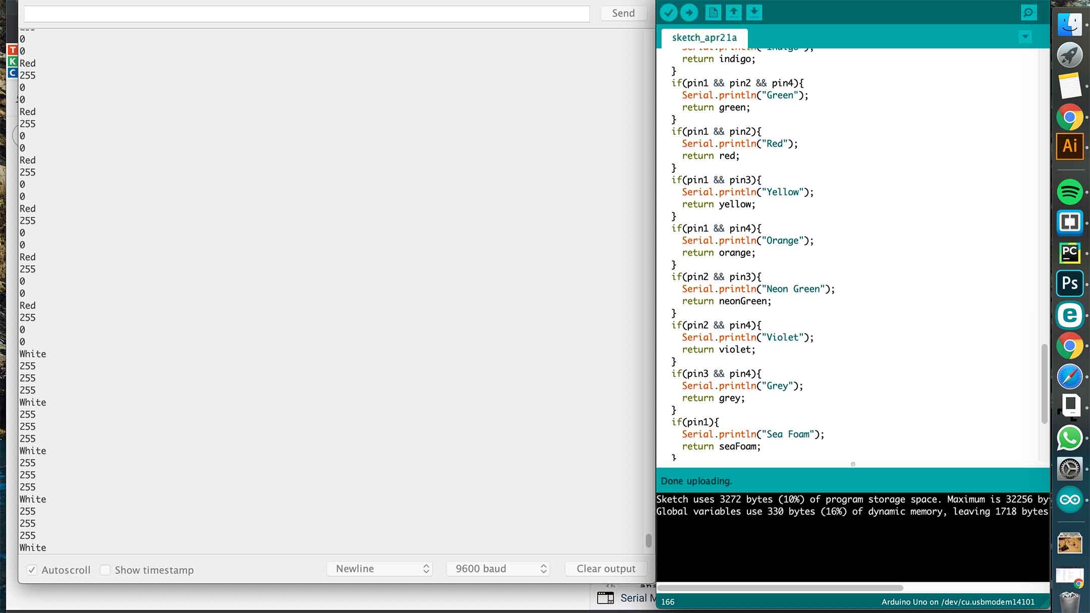
Basically, when I unplugged one of the pins and then pushed the button, I got these color combinations and could see it on my serial port.
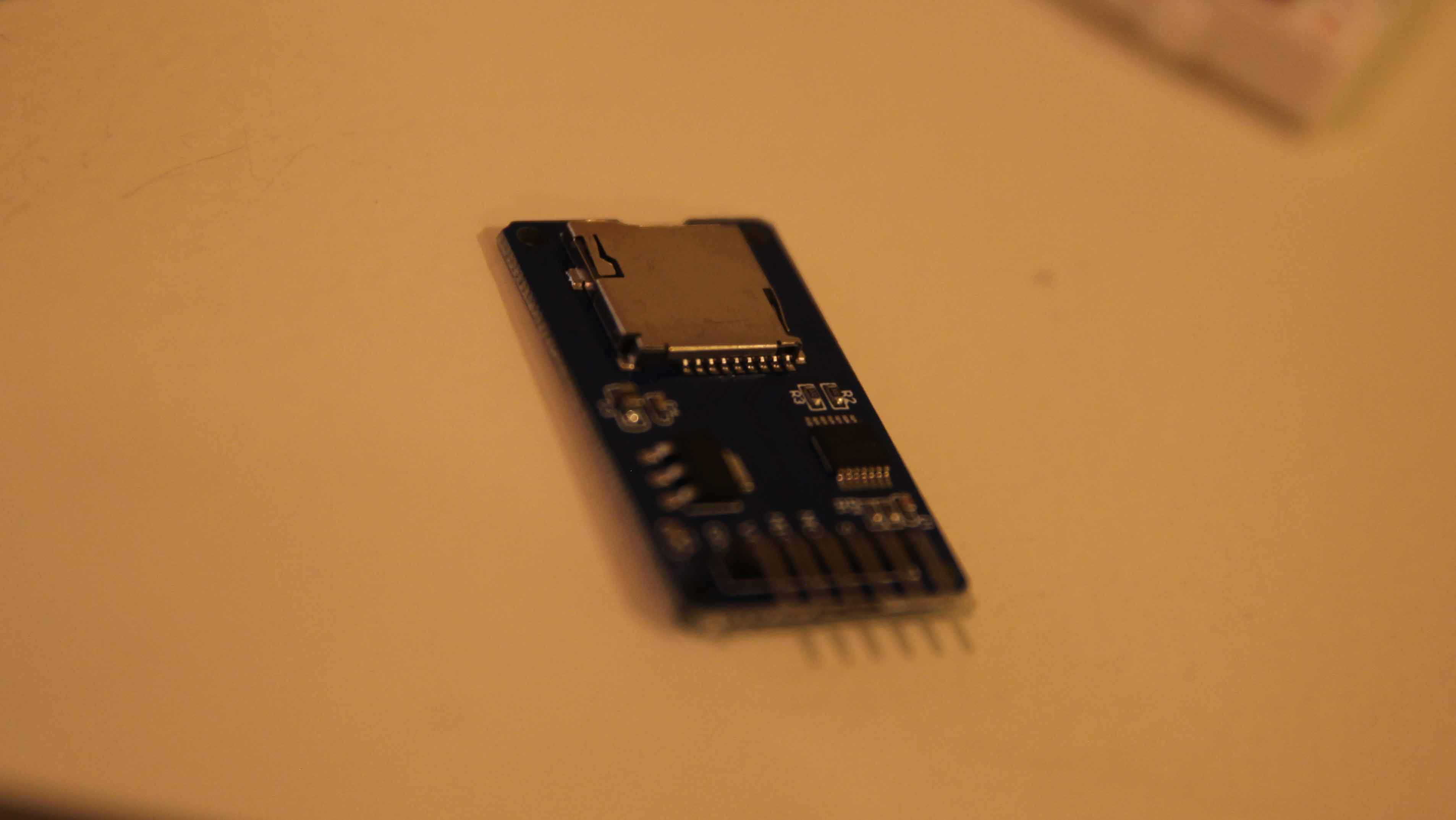
The next step is to hook up the SD card and input the color info on to it... And to get an actual swithc. THEN, once that works, I will start the schematic on Eagle.
RGB LEDs
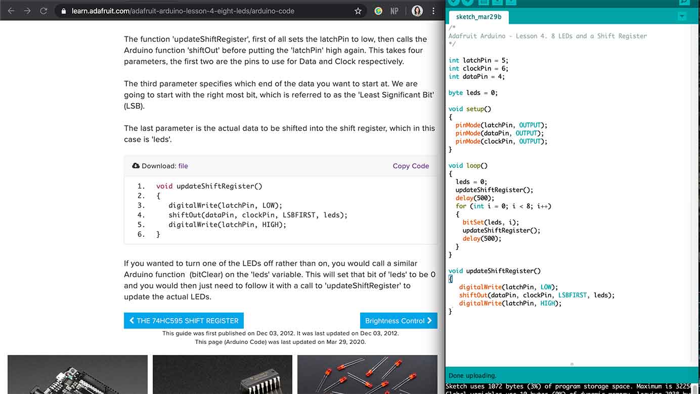
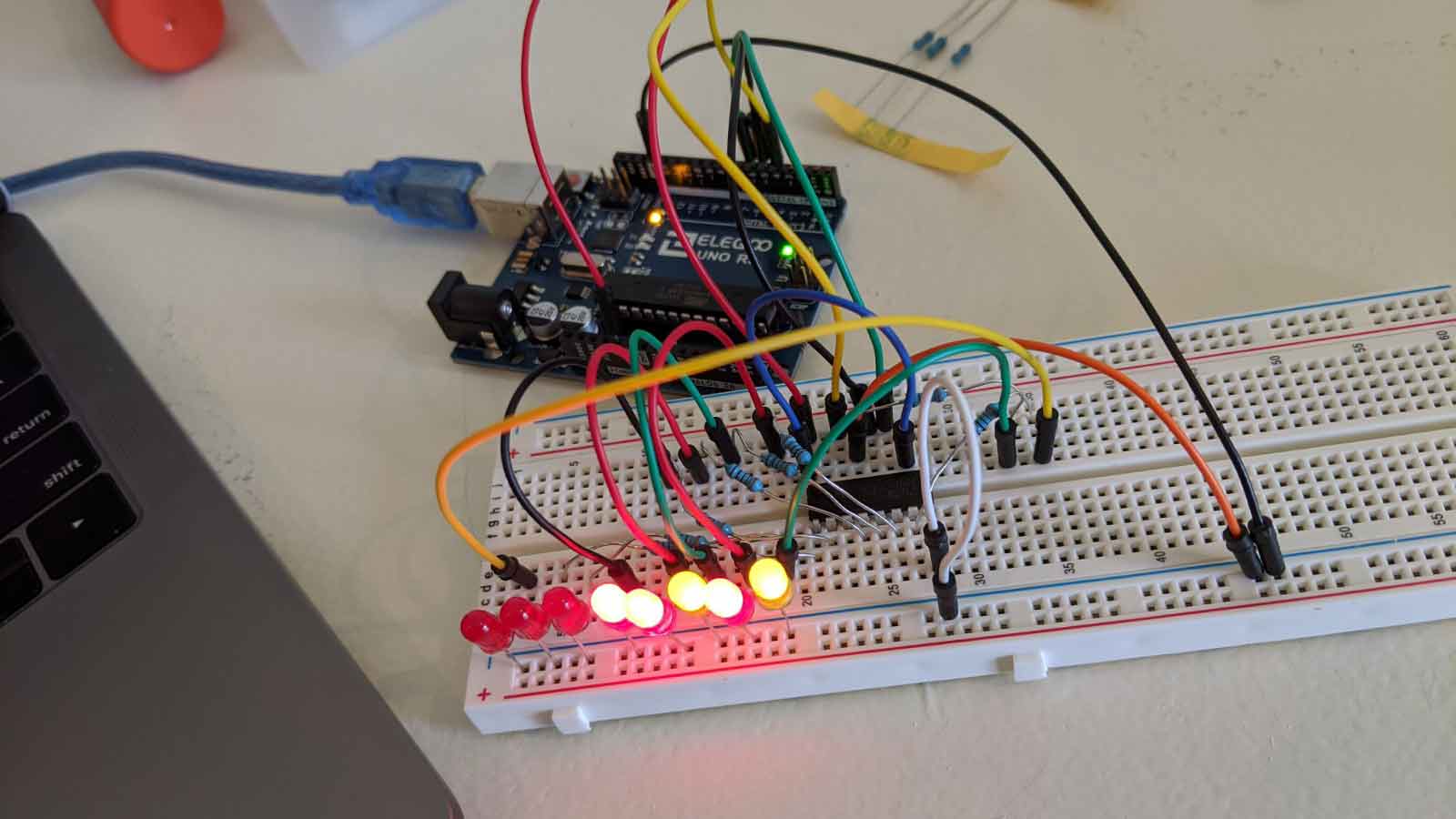
8 LEDs
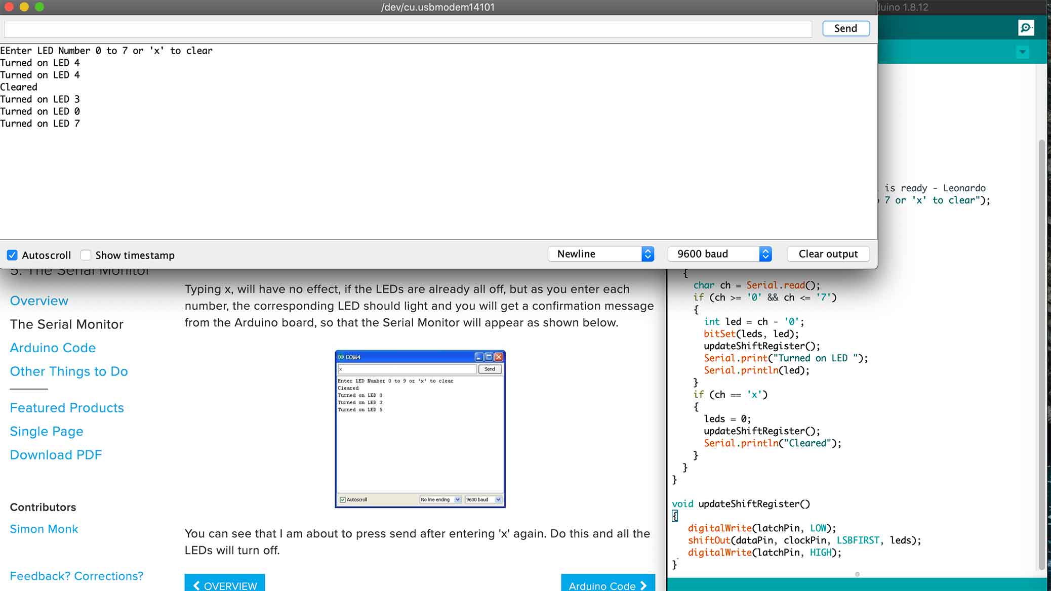
Serial Monitor
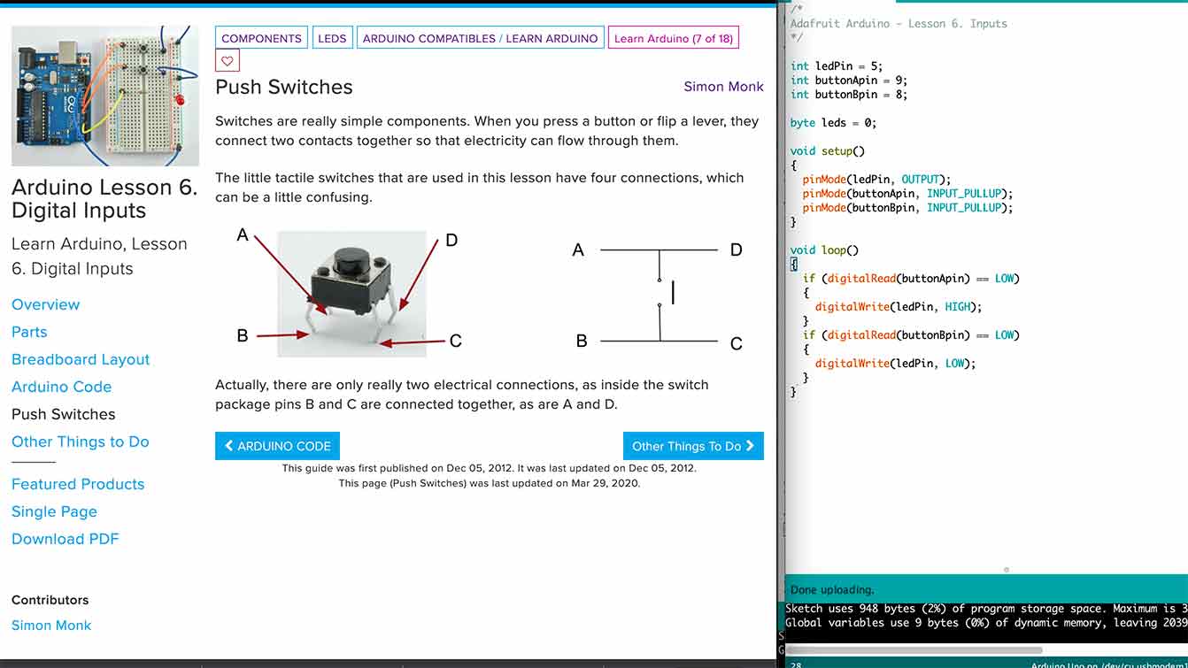
Digital Inputs
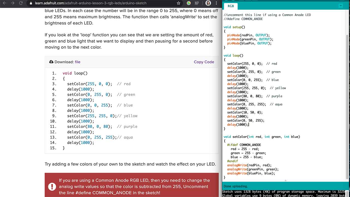
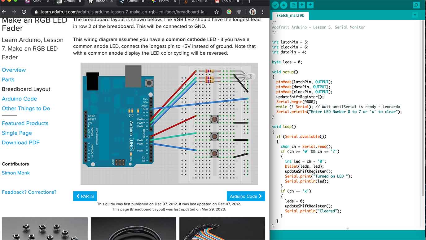
RGB LED Fader
Making Sounds
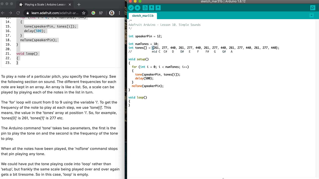
The command 'tone' has two parameters, first is the pin to play the tone on and the second is the frequency of the tone to play. This was a string of notes not on loop. Kind of fun.
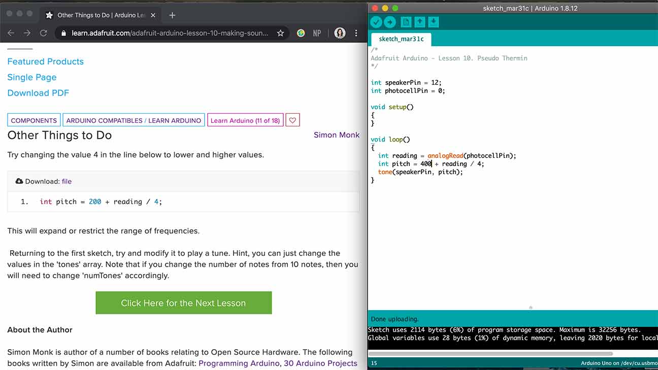
This uses a Photocell (Light Dependent Resistor) and the note changed based on the light input. I think...?
Motor
Song
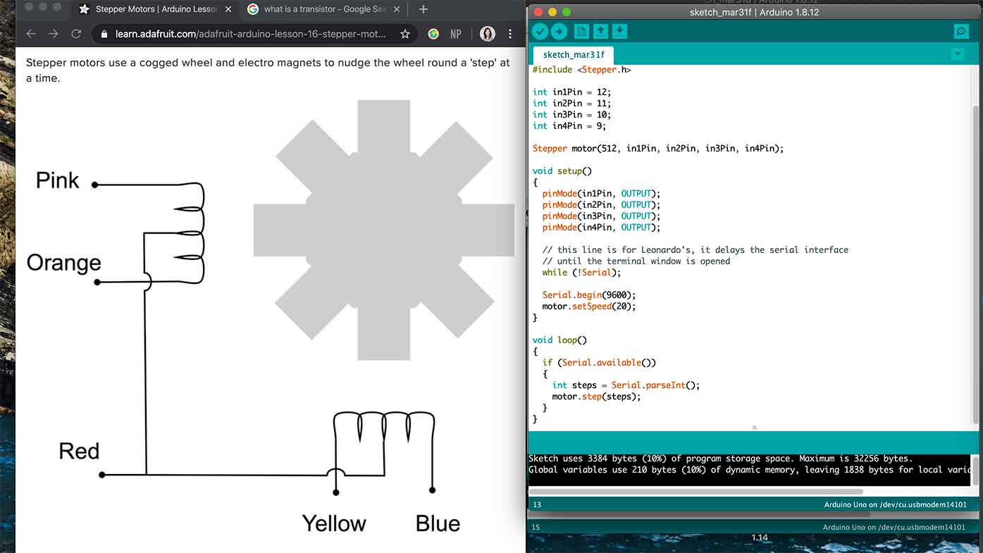
Stepper Motor
Full documentation...
of a board I made can be seen in Week 10..
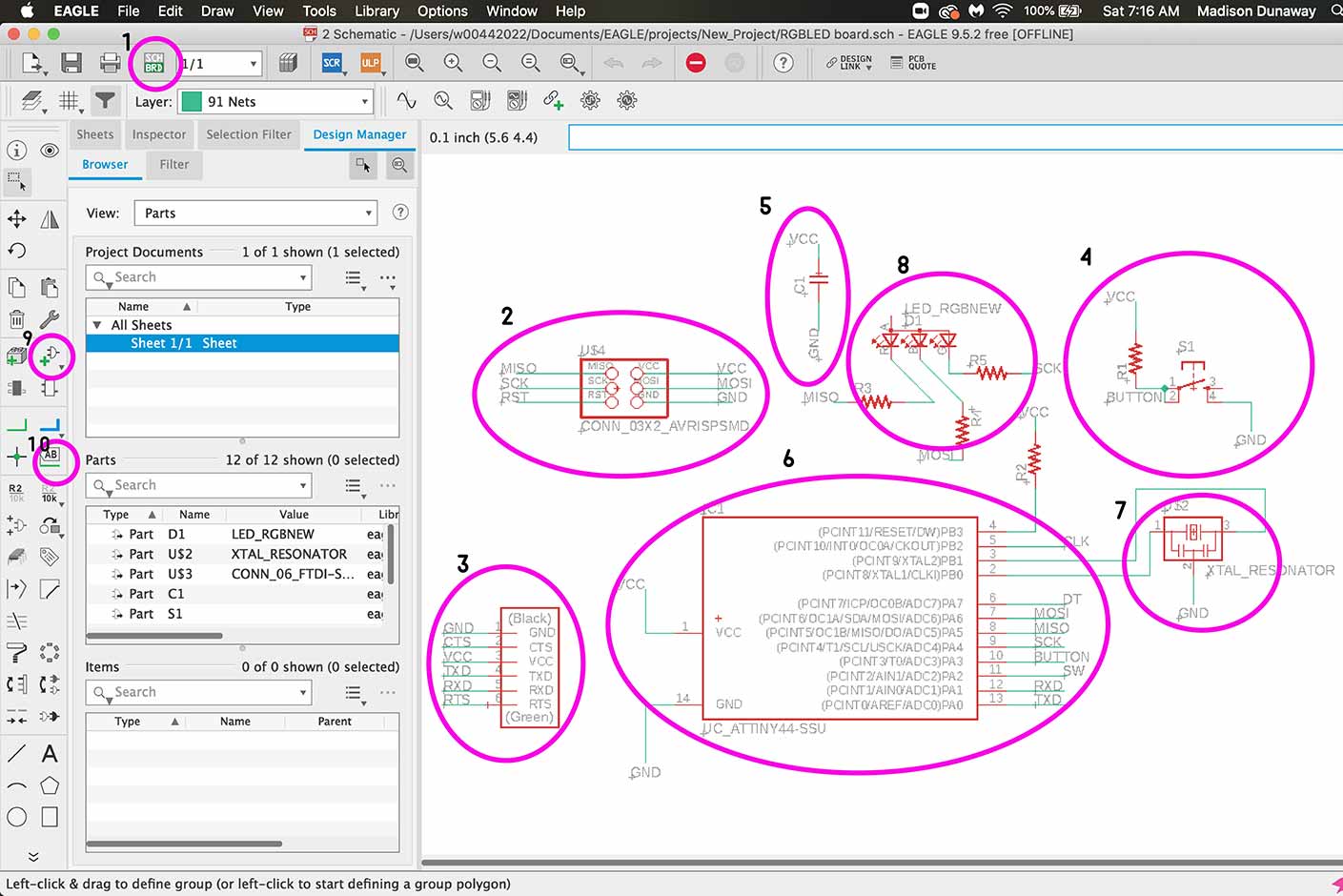
Let's go over some Eagle stuff for my own sake.
- This is how you switch back and forth between the board and the schematic.
- This is the ISP connector which is how you will initially program your board.
- This is the 6 pin header.
- This is the button.
- This is a capacitor.
- ATTiny44
- Crystal Resonator
- RGB LED
- How to add a part
- How to label and therefore connect a part.
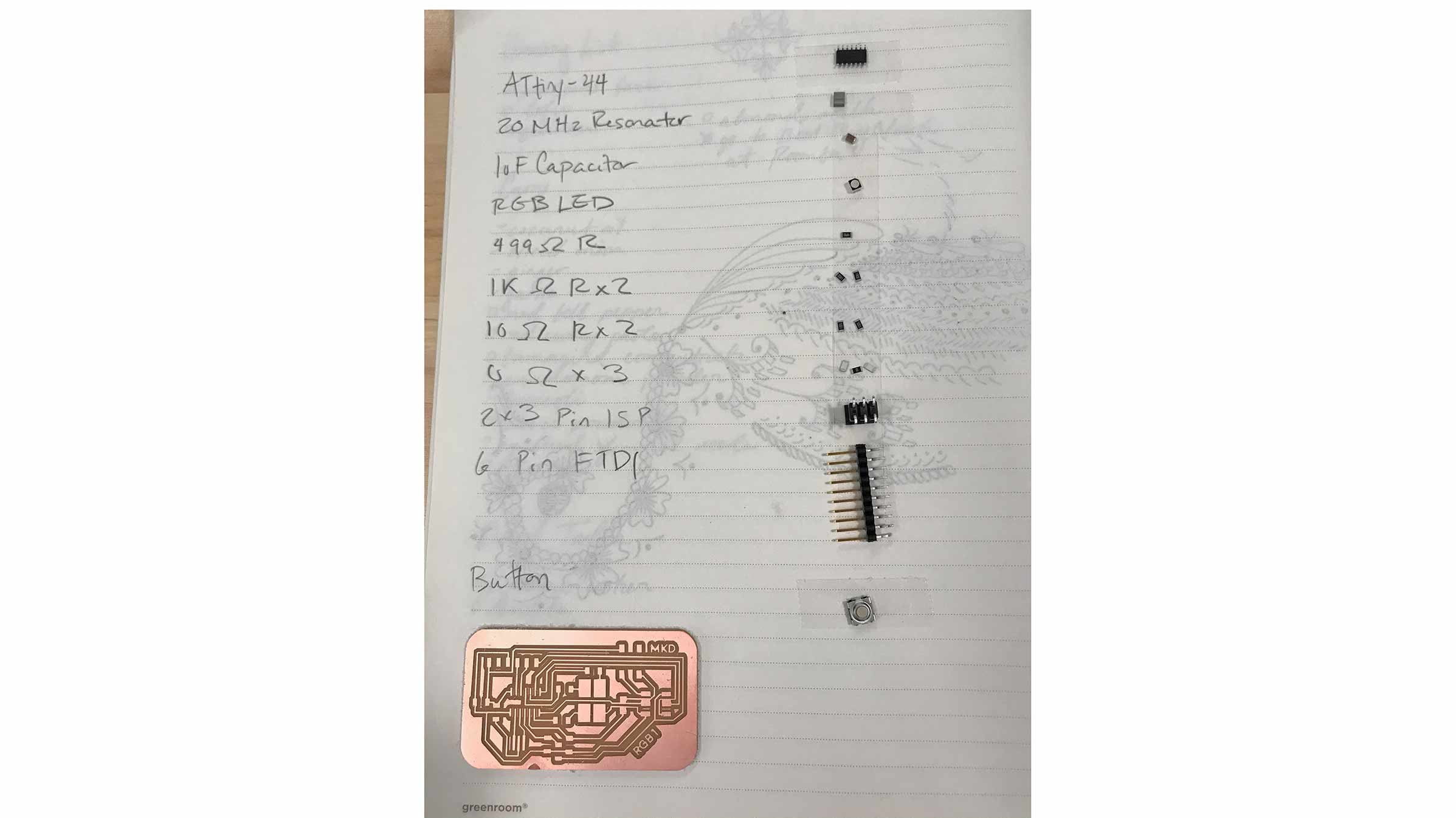
These are the parts needed. Pro tip: if you use double sided tape, they adhere to your parts list and your less likely to loose them when you start soldering or moving around.
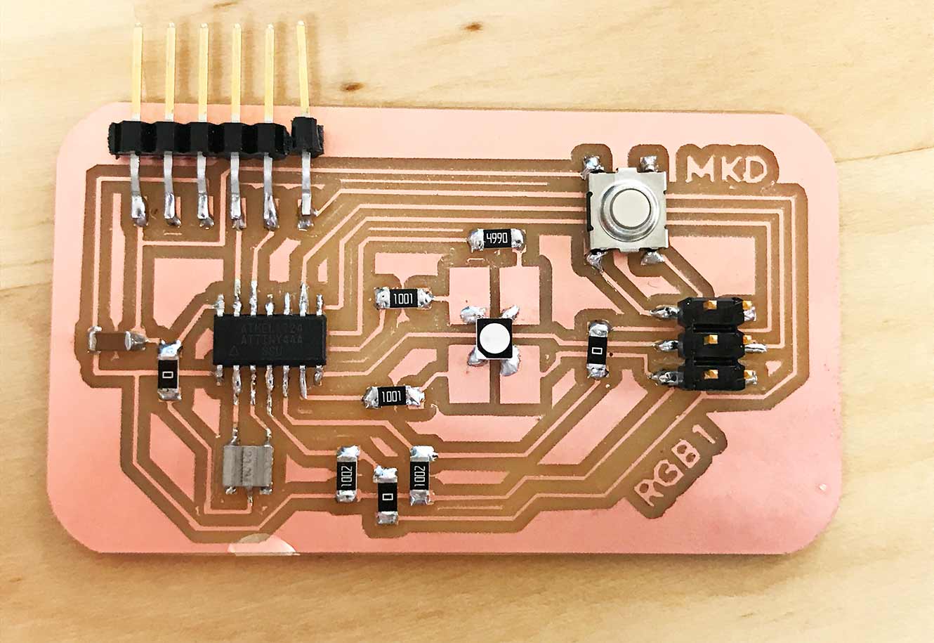
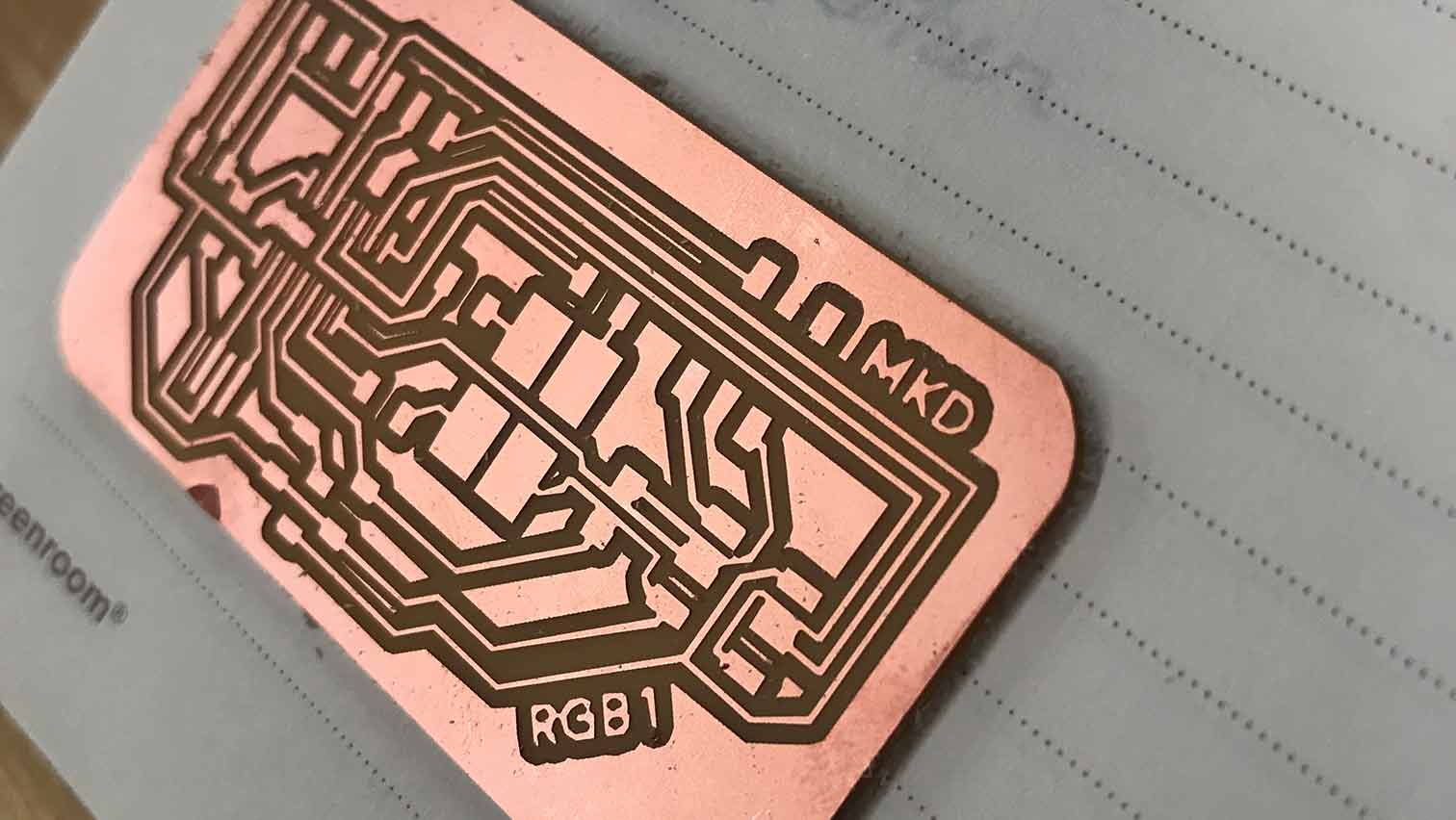
This is the board finally soldered!
Output = NeoPixels
So for my final project I'd really like to hook up some neopixels... and I've begun to think about how I'd do that here. If you're curious about how that turns out, check out my final project!
These were all helpful resources as I began to do some digging.
For more information on insight about output and my later findings on input as a rotary encoder and output as neopixels, please see my findings here.