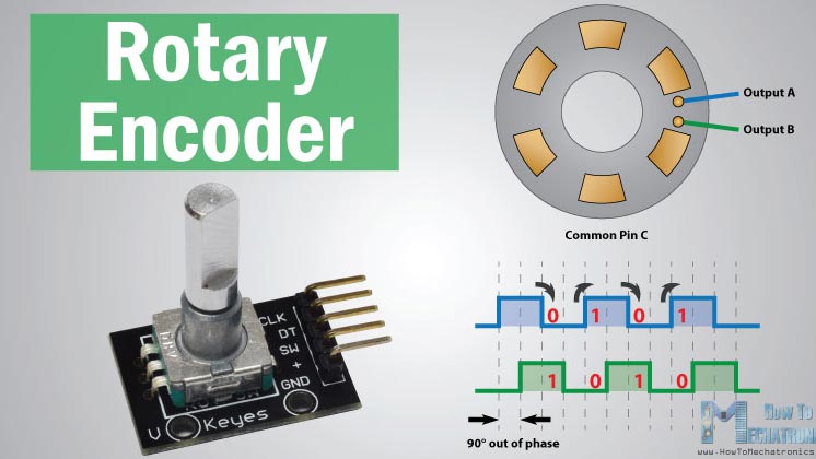

Rotary Encoders
To start, I want to say a student at a lab wheere I work really helped me better understand all of the components I needed to include to make this happen and I couldn't have gotten to this point (or it would have been a while longer) without picking his amazing brain! There are lots of different kinds of rotary encoders and you can make your own. A rotary encoder is a device that converts the angular position or motion of a shaft or axle to analog or digital output signals. I chose this type of input because I want the mechanism by which the color changes to be something along the lines of physically turning a knob... I realize there are many other ways I culd have done this but I ultimately decided to go in this direction. There are five pins to a rotary encoder: CLK for click (output A), DT (output B), SW for switch, + (vcc), and GND for ground. To begin, I wanted to try doing this with an Adruino and that meant CLK and DT needed to go to digital pins 2 and 3 and SW could go anywhere. I collected some supplies to get going which included a breadboard, jumper wires, and the rotary encoder itself. The first question though was does the rotary encoder have bounce. More on debouncing here. Switch bounce is literally bounce... most components I would use don't have good electro magnetic contact. Big cheap switches can have a waveform that can be somewhat eratic even with the span of a milisecond. Bounce in a mechanical switch can mess up an interrupt service routine in a microcontroller which we'd like to avoid. Some rotary encoders something in the them that eliminates most of the bouncing. If it doesn't have debouncing then we will need to add some small capicitors. The way we find this out is to use an oscillioscope.
Findings from the Oscillioscope
So I had never used an oscillioscope before today so i looked it up... "An oscilloscope, previously called an oscillograph, and informally known as a scope or o-scope, CRO, or DSO, is a type of electronic test instrument that graphically displays varying signal voltages, usually as a calibrated two-dimensional plot of one or more signals as a function of time." - Wikipedia. Let's break that down... they are kinda like a really dope multimeter that just samples voltage like a million times per second... with a screen and you can also export data (csv or png file) you can also modify the resolution of your voltage sample. This is a digital one which is great because it doesn't take forever to warmp up. The one in our lab is a RIGOL rated at 100megahertz... it seems like once you get past that, these get pretty expensive. We added some colorful rings called marking bands to keep track of what we were hooking up. There are two channels and an external trigger (which is not an aquisition channel) you can set up.


I attached channel 1 to DT and put channel 2 on CLK. Then attacted both to GND as well.

So the goal was to get these curves to right angles... this is the plastic non conductive scredriver. There is an adjustment screw on the probes. It's important that it's not conductive becuase capacitance stores charge and that's smoothes the slopes of the waveform.

After some calibration with the plastic screwdriver, we started getting something that looked more like a right angle. We can see 3V peak to peak.


Drawing out what the wavelengths look like to better understand how to write the code for the neopixels.
Arduino
First goal was just to get the built in LED on the Arduino to work.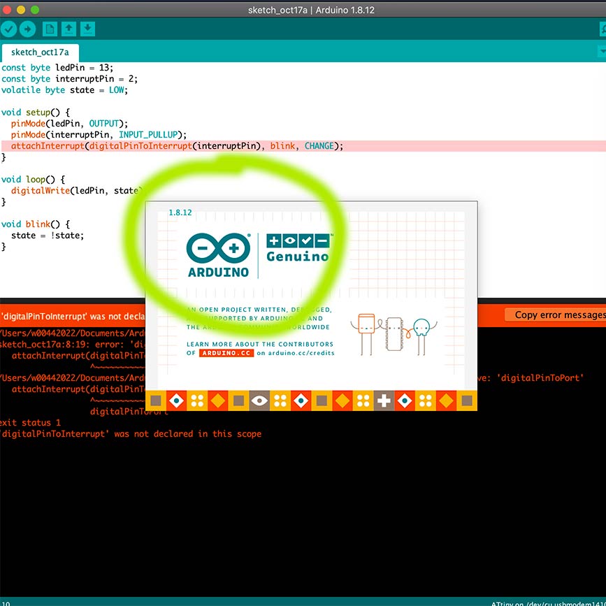
I immeditately ran into issues with Arduino... I updated it and then things were fine.
What I need to get done week by week.

This error happened multiple times and I eventually switched out the arduino and it started working...


So at this point things were still not working out and I was worried I read the initial waveforms incorrectly and that maybe in fact there was NO debouncing so I added a few capictors. Turns out it was an issue on the breadboard and then it worked!
Color
Before I dive into color, another tip about how to use Arduino with Neopixels: you need to download the library. At the beginning, I only read the beginning of this, but this documentation by Adafruit is very helpful. Also, can I just say, it's really empowering to see the culture at Adafruit and the company they are... and that women run it! Limor Fried is so inspiring! This is another site that helped get the code started.

Install THIS ONE. This page is also super helpful.

When I used an algorithm based on RGB, you can see the results below. Clear drops and not ideal.
So I originally just thought to use RGB because that's all I knew to use. Turns out RGB isn't ideal for what I'm trying to do. The video above is what my neopixels look like when I use code rooted in RBG. I researched this and started learn more about other color models and color spaces here. I then decided to try out HSL or HSV. HSL (hue, saturation, lightness) and HSV (hue, saturation, value, also known as HSB or hue, saturation, brightness) are alternative representations of the RGB color model. Turned out the best information I could find was on this Wikipedia page.

Wikipedia page equations...

How that turns up in my code...
So the code consists of global variables.. and two INTs.

I needed to learn more about ther seiral library for Arduinos and fount that it was serial.begin... on this site. To figure out more about attach interrupt within the context of Arduino, I looked here.
See first iteration of code here.
See second iteration of code here.
This is final code and it worked!
Designing the board
I chose to use KiCad instead of Eagle because it's open source and some peopl I know like it more than Eagle so I figured I'd give it a go since I'm not attached to Eagle yet. First, I will briefly describe the components I think I will need for this board and why.


I think I will ened up needing to change the code if I use this but hopefully it will work out.Purchase here.
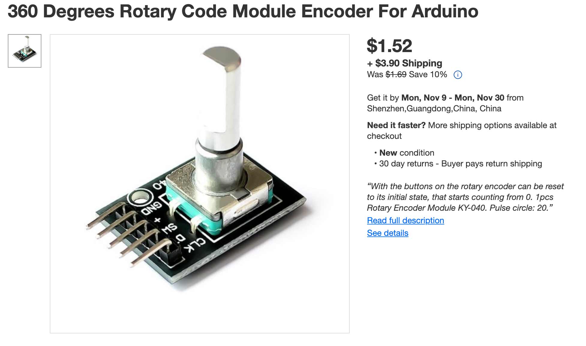
This isn't the exact one I'm using but very similar. The one I found was just in the lab. Purchase here.


What I need to get done week by week.
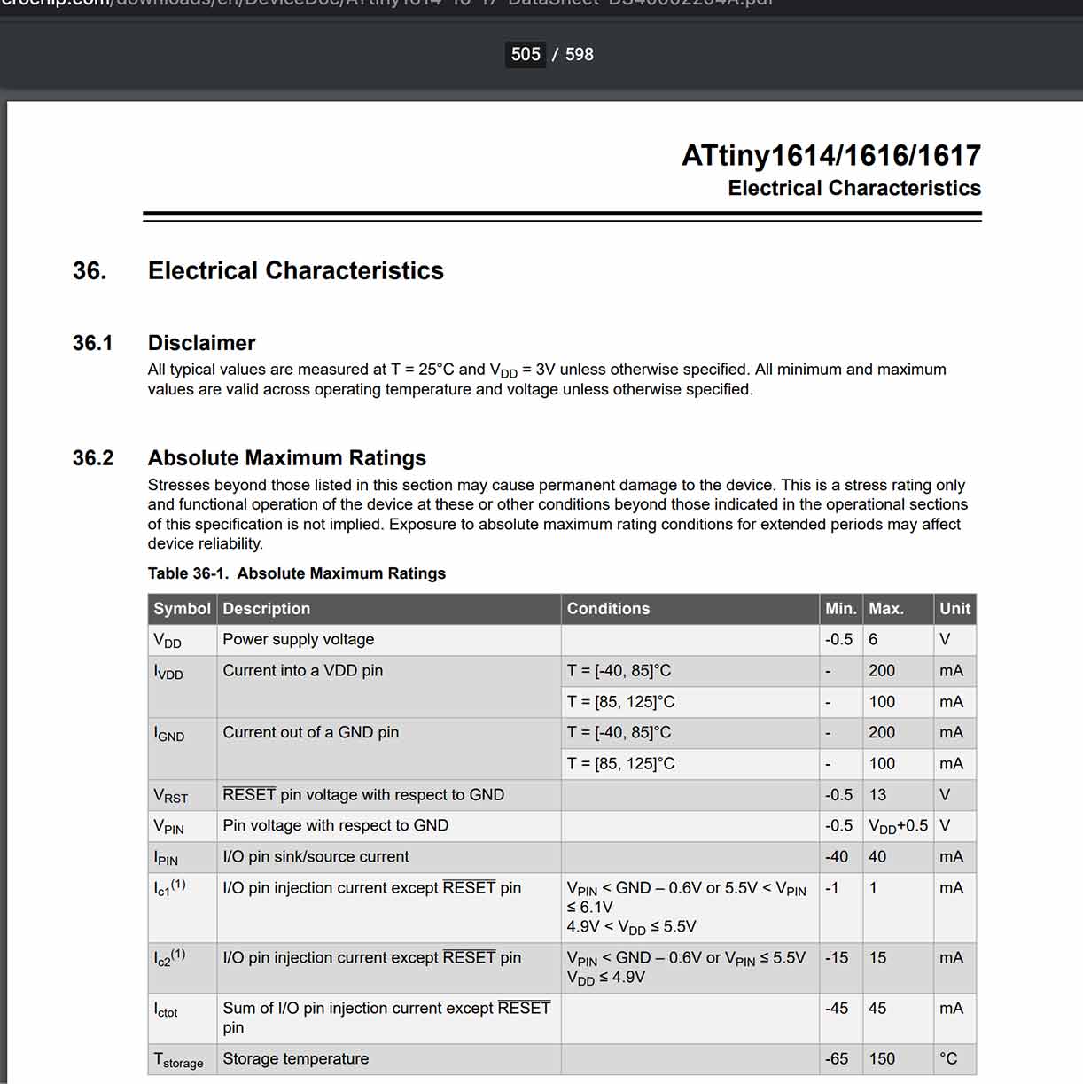
I had the AtTiny1614 on hand and decided to go with it. I then had to find a few things out from the datasheet.

From the datasheet.
I then needed to figure out how to download the library of components and found ot how to do that here.

This is similar to the circles of progress Neil originally explained as an approach to the Final Project. Thinking of it this was has made the entire endeavor much more doable and I highly recommend this was of thinking.


So I did watch a few tutorials about KiCad since this was my first time using it and honestly most of them wern't helpful because they were from a past version and apparently it s changed quite a bit. So of course, as you can see above, I started running into alot of errors.

I then realized I needed to assign each component a footprint...

I also had to go online and download the footprint for the USB.

There is a nice preview of each footprint. Also, when you have selected a footprint, you don't click OK, you just double click and then it turns red.

Once you do all of the assigning of footprints, you need to create the actual layout and route everything. It turns out this does have a pretty good autorouter but this looked simple enough that I could try. Also, another tip: when I was in this mode, the view was really zoomed out and it appeared by board wasn't there. If you select "Fit to Screen" you can find it.

Getting there with the routing...

I ended up milling this one on the roland...
It turned out kind of terribly. I can't get the Roland at my lab to cut... and the USB traces were WAY too small to be cut... and I kinda lost my know how when it came to the soldering part.

I ended up kind of starting over and created a board with just the AtTiny1614, pin headers, capacitor, and some jumper cables... I took out the USB becuase the traces were too small.

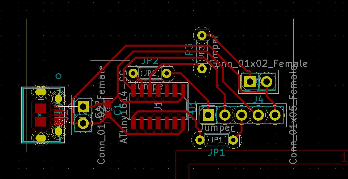
And then I started over again... and again... but ended up with this new schematic which only has one AtTiny1614, a 5 pin header for my roatery encoder, a 2 pin programming header for programming the microcontroller, a 2 pin header for programming the neopixels, a 2 pin header for ground and power, and 2 pads for a capacitor, and jumper.

At this point... you can probably see what happened here. The traces for the microcontroller didn't turn out most likely becuase I just didn't export it properly and had the connections to large. This was at 9PM on a Saturday and I was done for the day. I did feel pretty defeated and started to question if I could really do this.

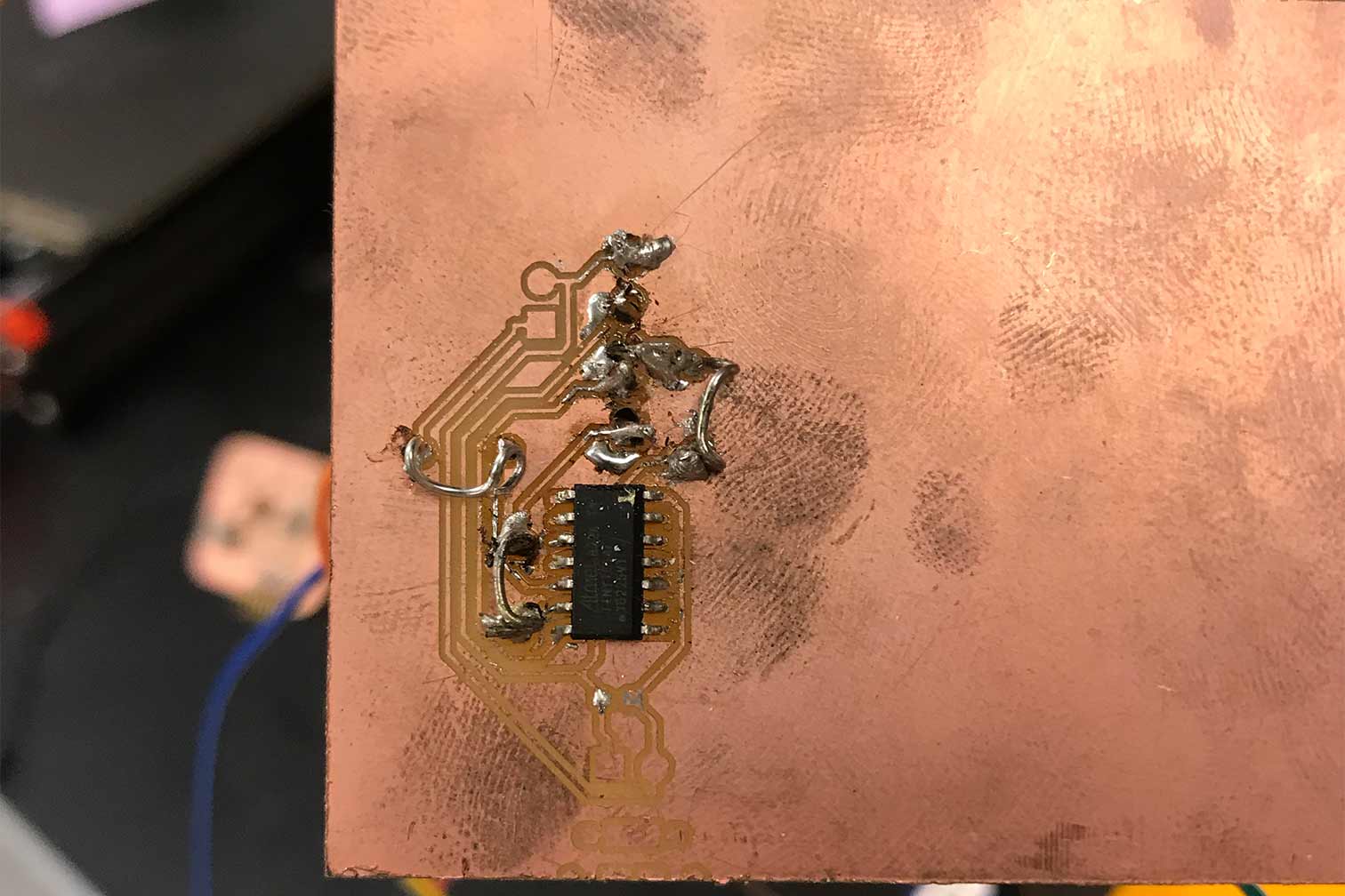
Then I milled another one! And started to solder. The board itself had a few errors but nothing I didn't think I couldn't work with.


At this point, I performed a ton of continuity tests and found I had a short circuit near the capacitor and the at tiny. I spent about an hour de soldering and re soldering everything until the multimeter stopped making that irritating buzzing noise which meant, no more shorts!! Maybe... lol. I went to sleep. Tomorrow I will try to program it and then we will really know what went wrong.
It's tomorrow! Time to program.
This turtorial is extremely helpful. It goes through step by step how to program the AtTiny processors. Also my man Spence has some important information here on the chnages made in the tinyNeopixel library.


All the wires started getting confusing.
I added some resistors (2 220s).

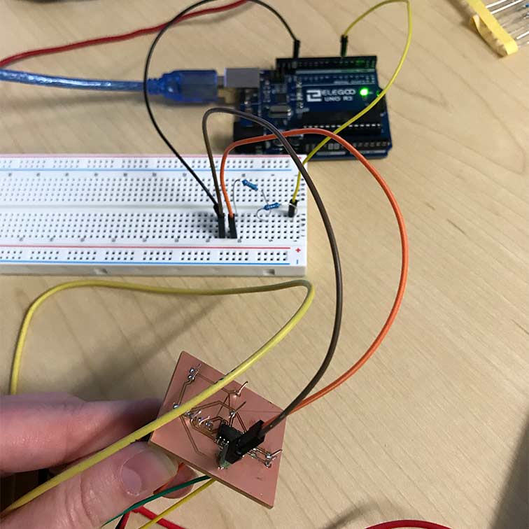
So the Arduino is hooked up to a computer... the power is coming from the bench supply. I did add a capacitor. Its purpose is to bypass coding the actual Arduino and to send the code to the. It resets the arduino.

And then I got this error 100 times. AHHHH!!!!!!! I tried adding a capacitor.. then it just happened but later. I took out the resistors, added the resistors back, changed the code... checked the breadboard, used THREE different arduinos... D: I think I'm going to make a new board now because I did have a hard time soldering the ATtiny1614 and maybe I busted it?
So this was all the error of my soldering... After a million continuity tests, I fixed all the issues for the time being so now onto new errors hopefully within the software!
We added a 10kiloOhms resistor between switch and VCC becuase there was no pull up resistor so the line was floating in the electrical breeze. Also, we added a 10 mf capacitor between GND and switch so even if bounce was called by tapping or moving the lid, it would need to be longer than a few microseconds long.
At this point, everything kinda of fell into place quickly and you can see the final product in my video!
Helpful Links
- Did I kill my neopixel strip?
- Actually the attiny1614 doesn't have a serial monitor....?
- The neopixels I bought
- Good guide on how rotary encoders work
- another one
- one more...
- Helpful FabAcademy student page
- VERY common error.
- VERY helpful video!
- My man Spence.
- The tutorial I should have started with.
- Spence killing it again