Assigment #9
Inpot Devices
The 10th assignment of the Fab Academy program is about input devices. What we have to do is to measure something using our sensors and a microcontroller
1 – the sensor
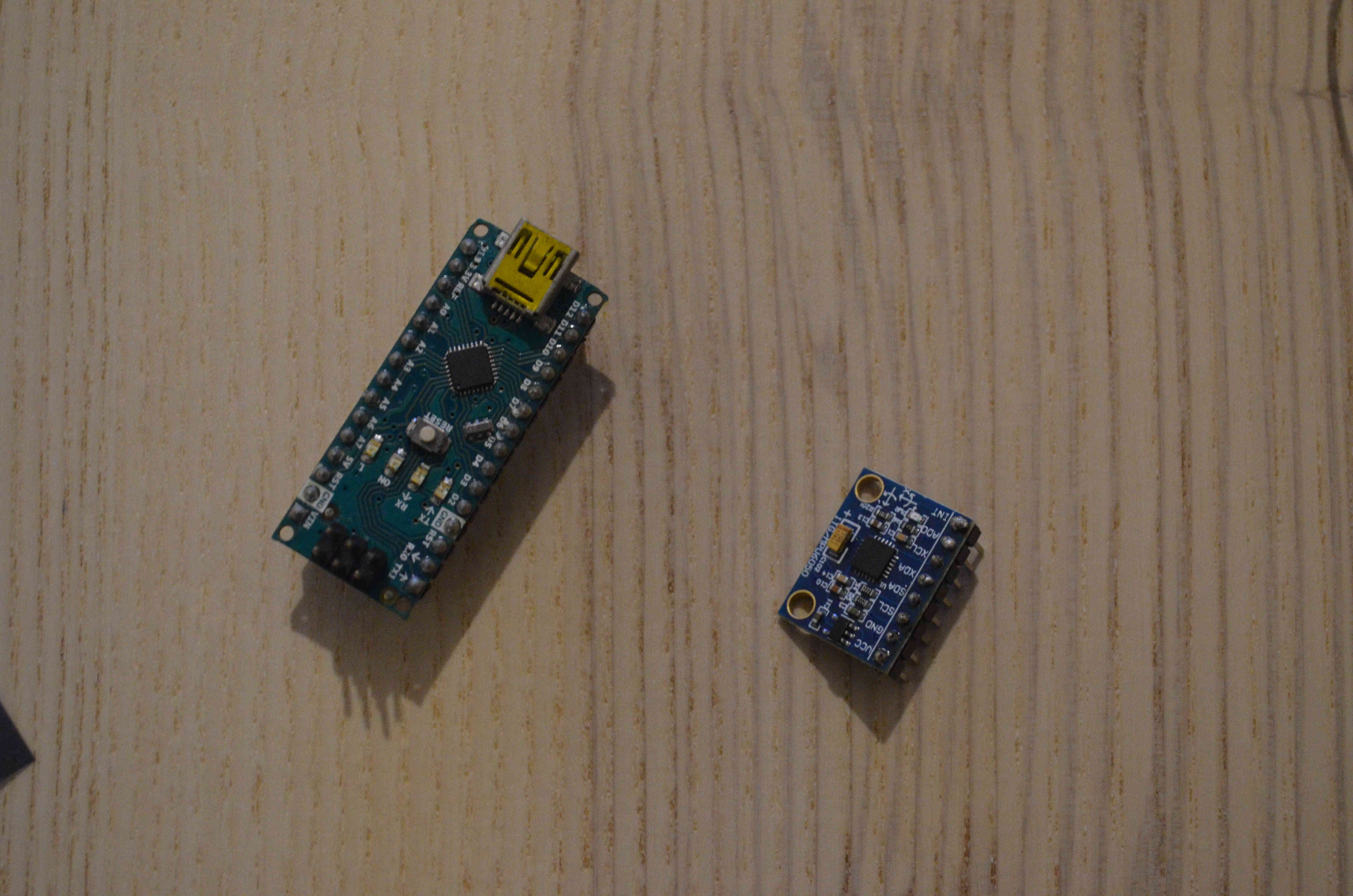
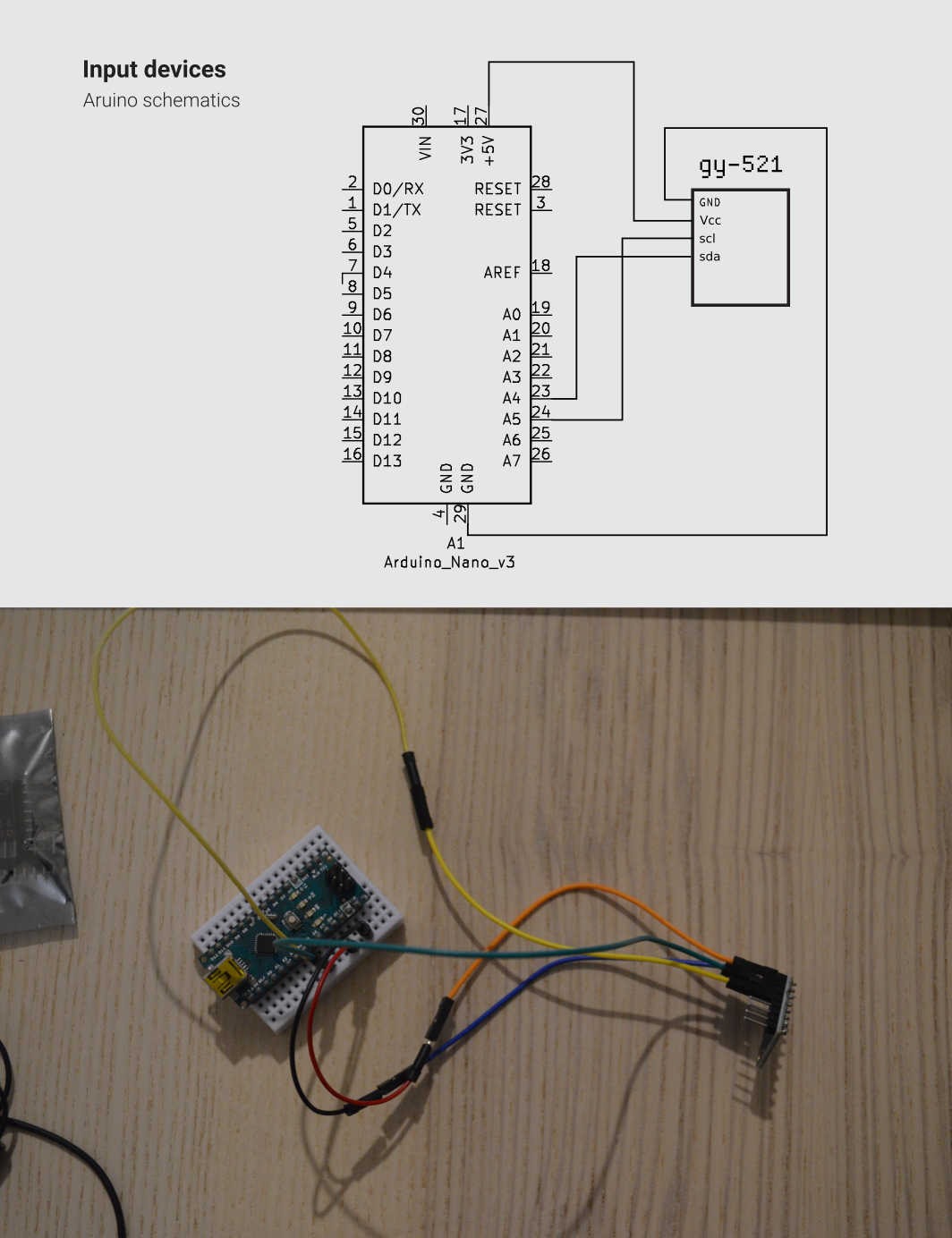
Due to the awful Corona Virus pandemic that is currently hitting hard on our planet it is still really hard to access labs. Mine is no exception, and because of that i’ll be using an Arduino Nano to fulfill this assignment. The sensors I’ll be using is a MPU-6050 embedded in a GY-521 module. That is because It’s the one I’ll be using in my final project to detect the inclination of the Midi controller I’mmdesigning. To guide me in the process I used this tutorial
2 – The code
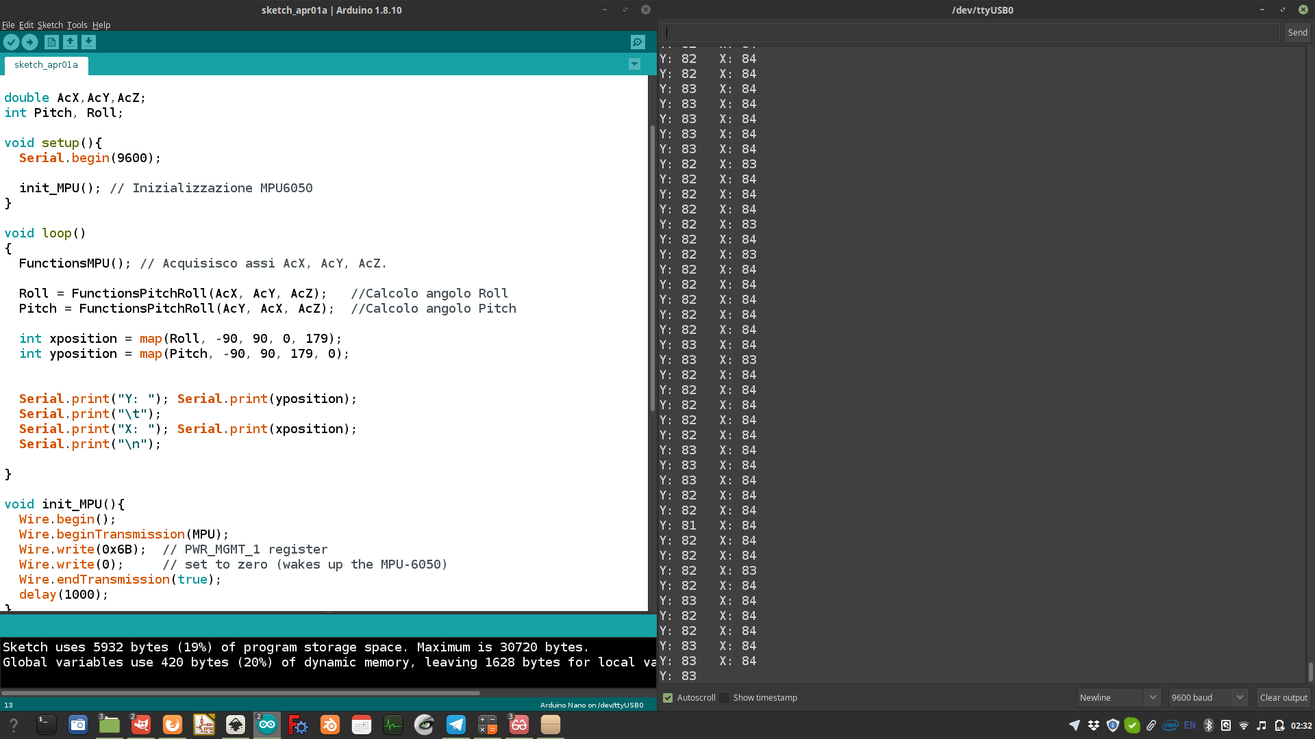
The code it’s a little more complex than the one I made for the Embedded programming assignment. I had to use a library called “Wire”, in the code there are a few functions that turns the signal picked by the sensors into degrees, and some mapping functions to make the numbers easier to use as a reference. Once the code was written I uploaded it using the good old Arduino IDE:
#include

#include


#define MPU 0x68  // I2C address of the MPU-6050


double AcX,AcY,AcZ;

int Pitch, Roll;


void setup(){

  Serial.begin(9600);


  init_MPU(); // Inizializzazione MPU6050

}


void loop()

{

  FunctionsMPU(); // Acquisisco assi AcX, AcY, AcZ.


  Roll = FunctionsPitchRoll(AcX, AcY, AcZ);   //Calcolo angolo Roll

  Pitch = FunctionsPitchRoll(AcY, AcX, AcZ);  //Calcolo angolo Pitch


  int xposition = map(Roll, -90, 90, 0, 179);

  int yposition = map(Pitch, -90, 90, 179, 0);


  Serial.print("Y: "); Serial.print(yposition);

  Serial.print("\t");

  Serial.print("X: "); Serial.print(xposition);

  Serial.print("\n");


}


void init_MPU(){

  Wire.begin();

  Wire.beginTransmission(MPU);

  Wire.write(0x6B);  // PWR_MGMT_1 register

  Wire.write(0);     // set to zero (wakes up the MPU-6050)

  Wire.endTransmission(true);

  delay(1000);

}


//Function to calculate angles

double FunctionsPitchRoll(double A, double B, double C){

  double DatoA, DatoB, Value;

  DatoA = A;

  DatoB = (B*B) + (C*C);

  DatoB = sqrt(DatoB);


  Value = atan2(DatoA, DatoB);

  Value = Value * 180/3.14;


  return (int)Value;

}


//Function to get  X,Y,Z from MPU6050

void FunctionsMPU(){

  Wire.beginTransmission(MPU);

  Wire.write(0x3B);  // starting with register 0x3B (ACCEL_XOUT_H)

  Wire.endTransmission(false);

  Wire.requestFrom(MPU,6,true);  // request a total of 14 registers

  AcX=Wire.read()<<8|Wire.read();  // 0x3B (ACCEL_XOUT_H) & 0x3C (ACCEL_XOUT_L)

  AcY=Wire.read()<<8|Wire.read();  // 0x3D (ACCEL_YOUT_H) & 0x3E (ACCEL_YOUT_L)

  AcZ=Wire.read()<<8|Wire.read();  // 0x3D (ACCEL_YOUT_H) & 0x3E (ACCEL_YOUT_L)

}
3 - testing the code
To see if the code was working well I opened the serial port, and used a serial monitor to visualize the data picked by the sensor. The code worked well and I managed to reach a poit where the device is able to constantly detect the angle of the device towards the X and Y axis
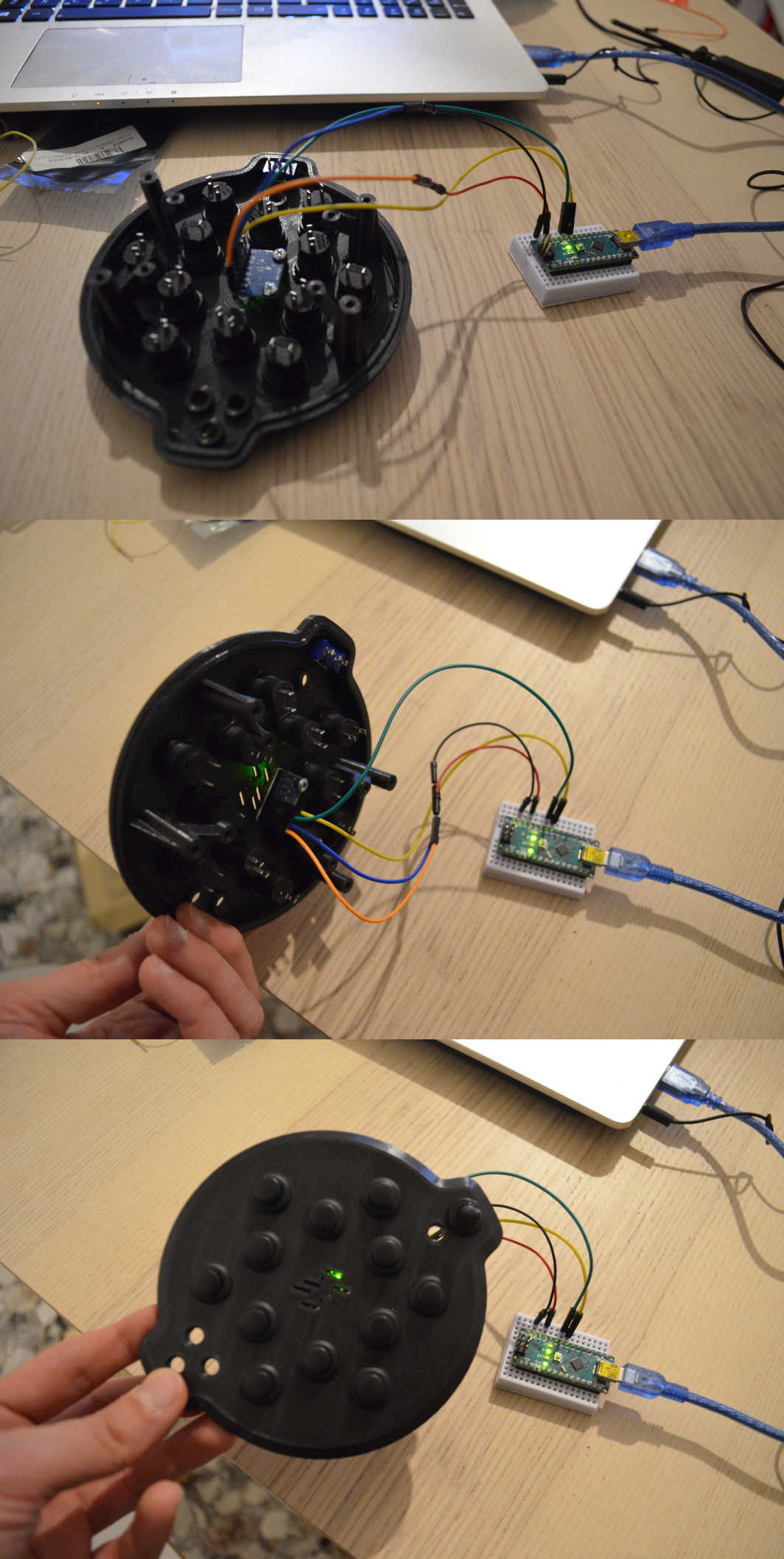
5 – test with the final project top shell
Last thing I did with the GY-521 was to attach it to the top shell of my MIDI controller to see how it looks. I really like the way it is possible to see the LEDs of the modules from outside, and the device worked very well once again
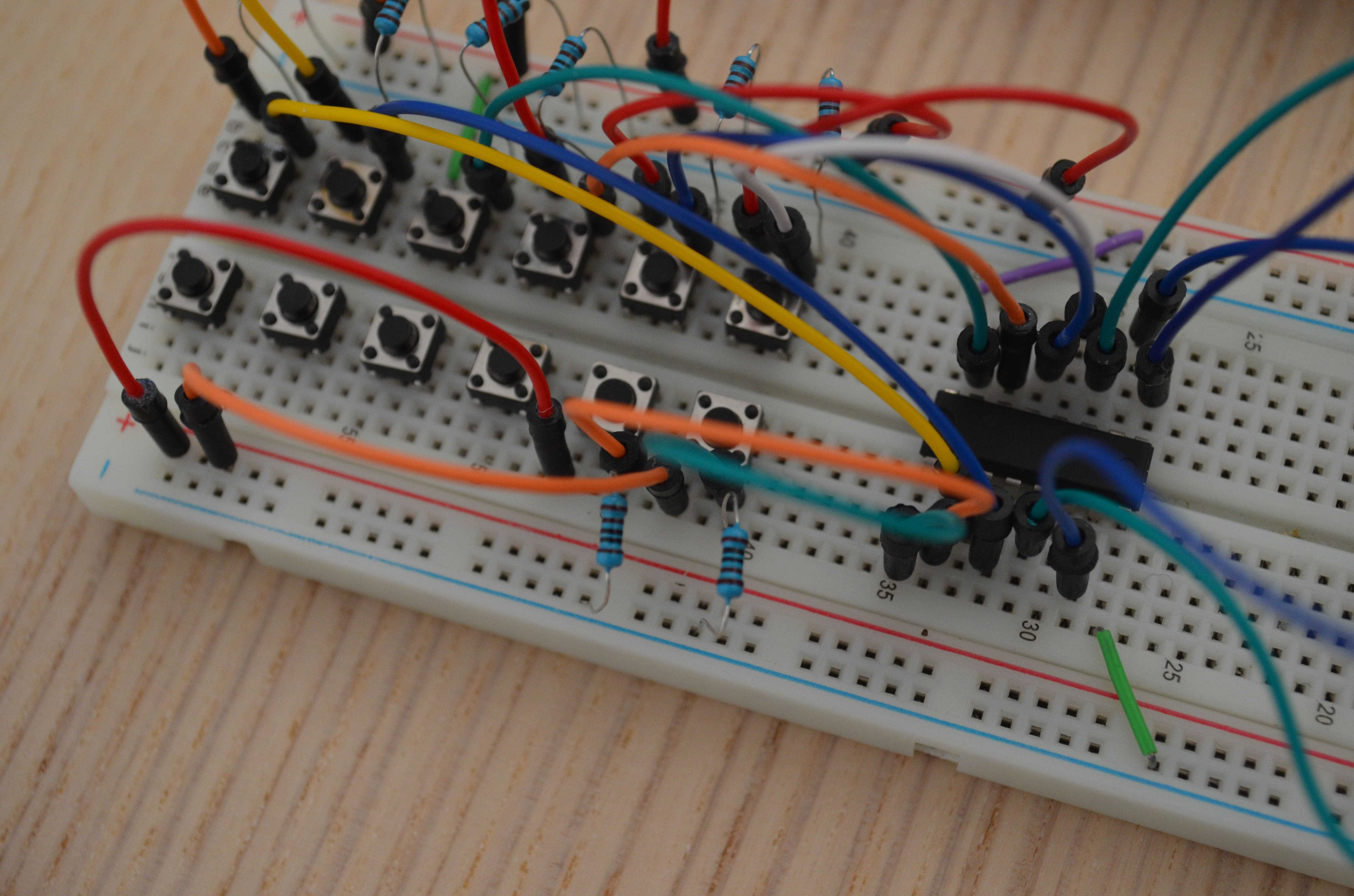
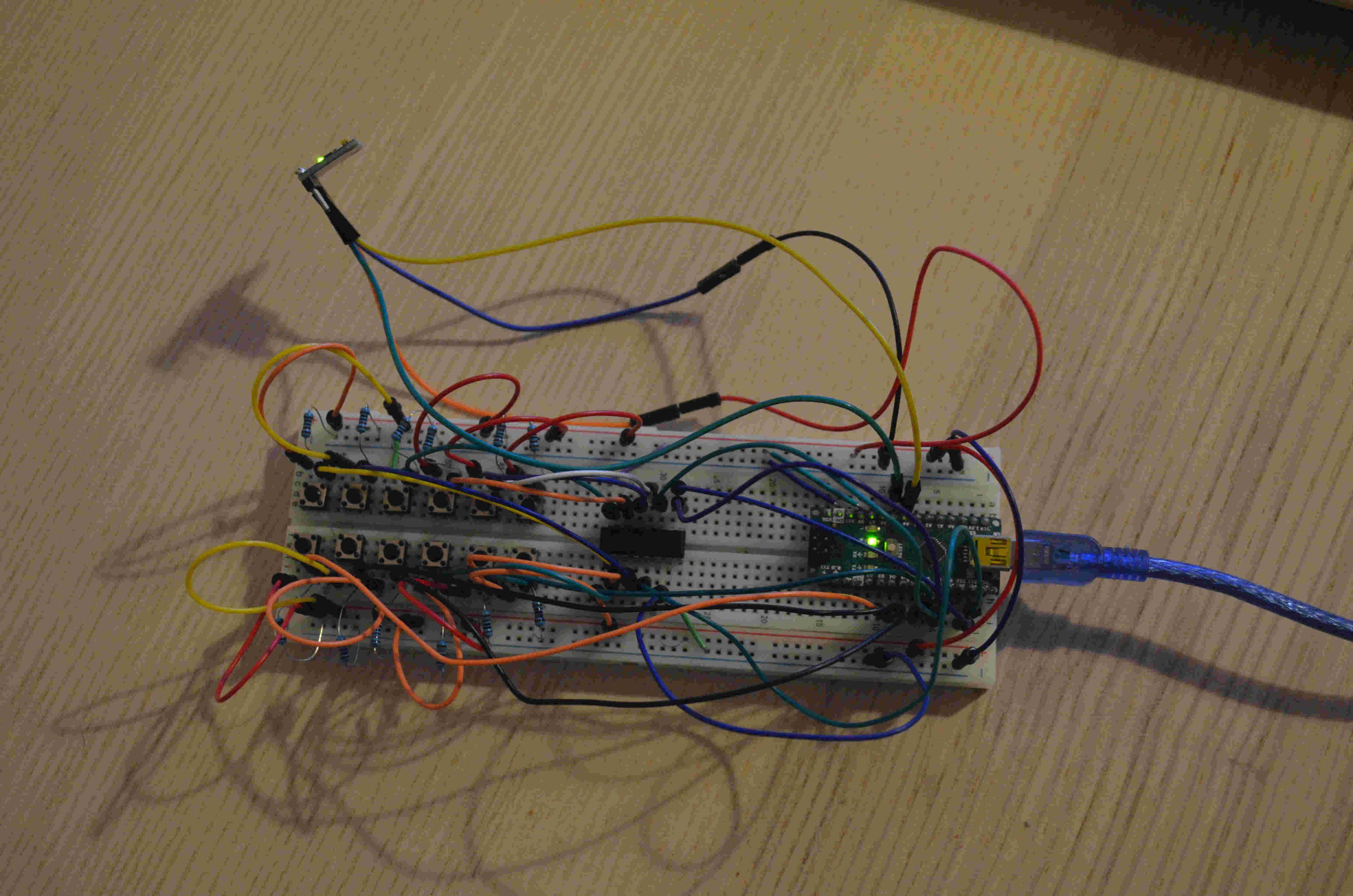
6 – MUX and buttons
In order to achieve the result of having 12 buttons to be used as notes for my final project I’ll also need a multiplexer (aka MUX) So I got this fantastic SN74HC1.
A multiplexer is a chip that allows you to connect several inputs (in my case 8) and send them through one single pin.
So I added the MUX connected with 8 switches and 4 extra buttons directly to the controller, so that in total I have 12 inputs.
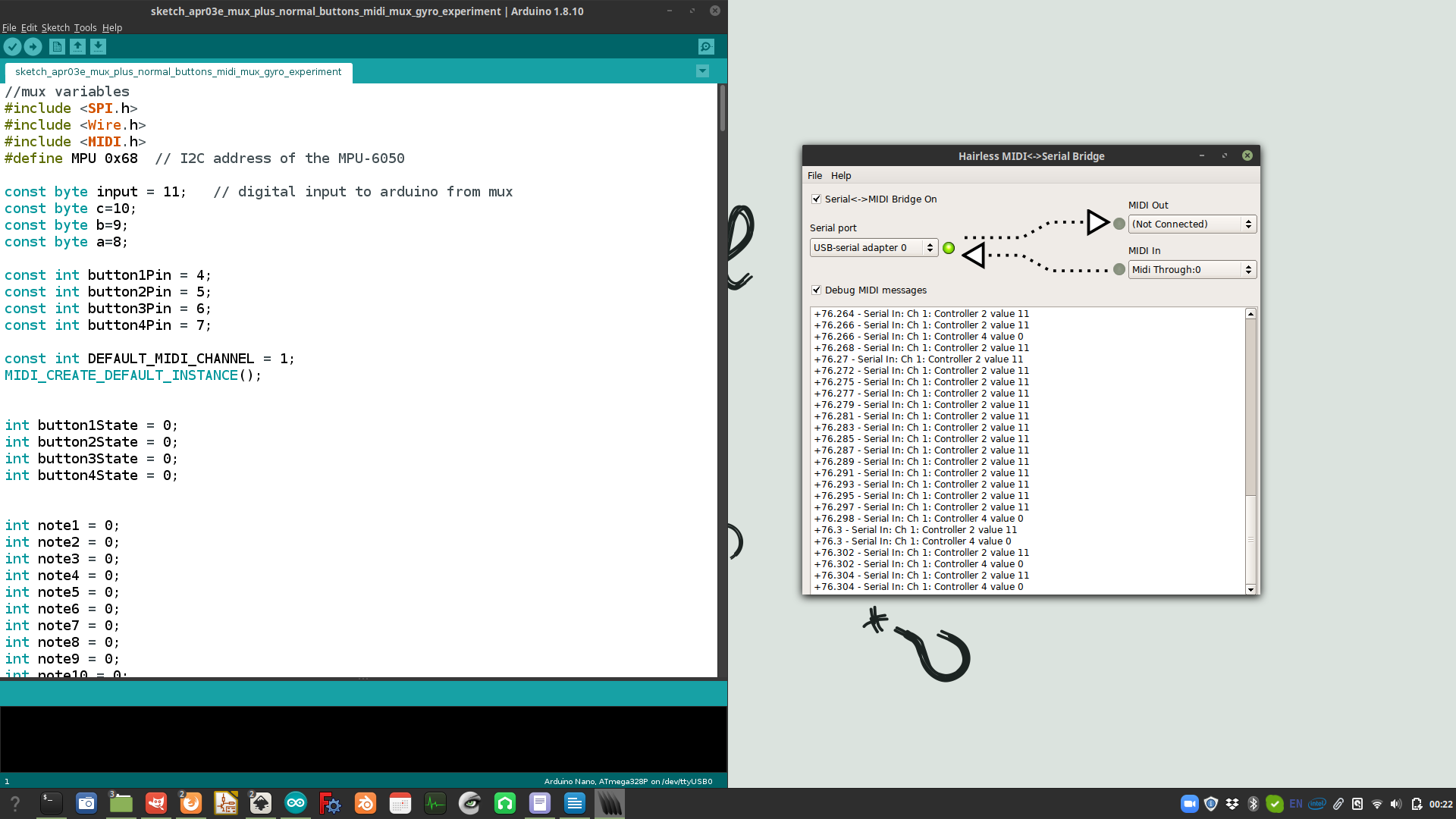
7 – Coding the MIDI device
To further test the success of this operation(s) I went straight to the MIDI library , and assigned to each of my buttons a midi notes, as well as mapping the gyroscope data in 4 different MIDI Change Control values that can be assigned to control effects, volume and other aspects of the musical instruments. To check if my code was correct I used a software called Hairless . Hairless is a virtual MIDI machine that takes data from a serial port and turns it into proper MIDI data. After a few tweaks and changes in my code I managed to send good MIDI signals to Hairless!
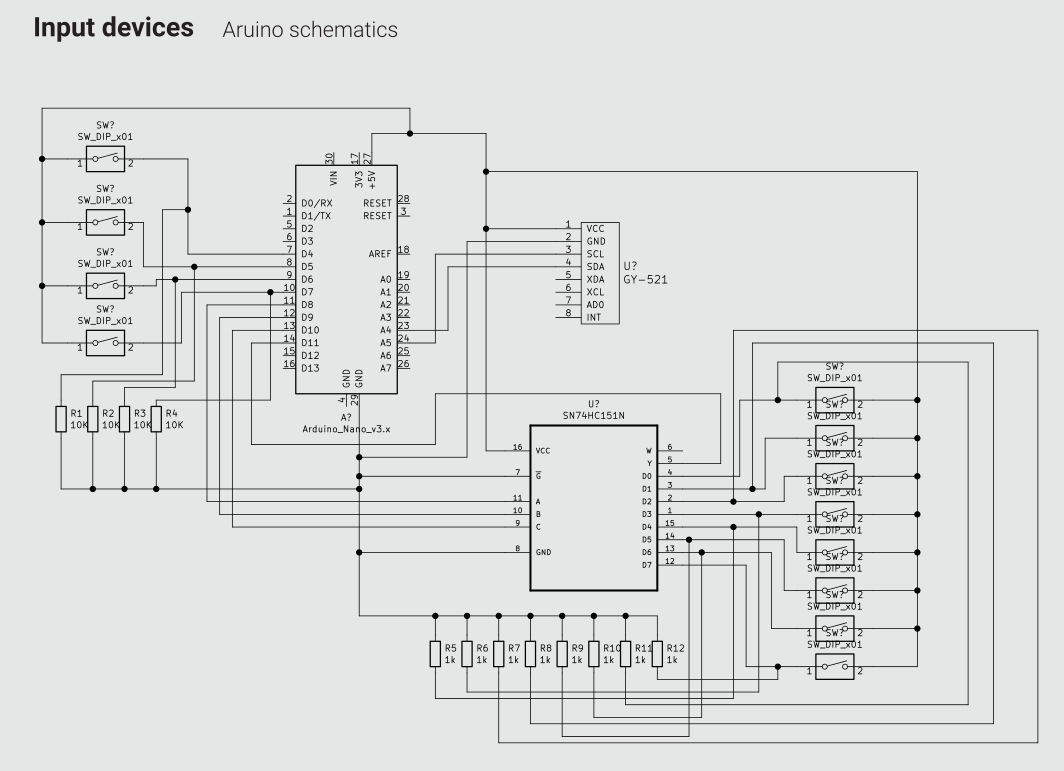
8 – Designing a board for the input device
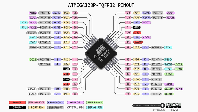
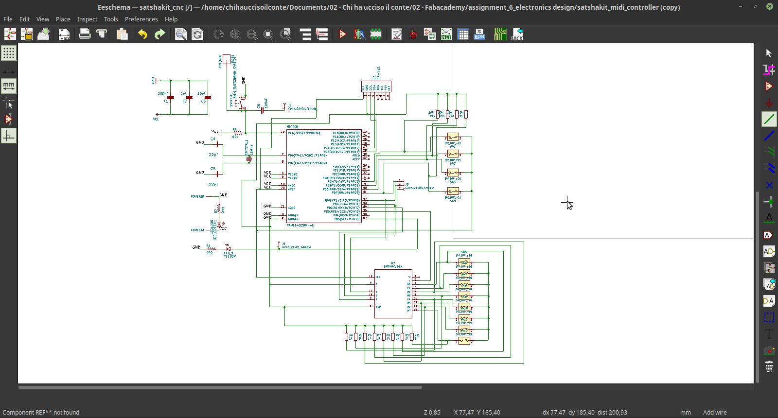
To complete my assignment I'm going to design a PCB specifically desiged to work with the input devices that I tested during this week. To produce the real board was unfortunately impossible due to the pandemic that is hitting hard the world. But my global evaluator suggested to work on this to improve my PCB design skills. So, inspired by the satshakit , I observed in depth an ATmega328P. Observing the datasheet and the pinout of this controller I managed to connect the input devices to the chip and make a schematic of my circuit, all done with KiCAD.
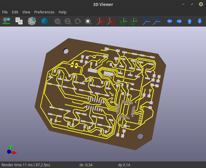
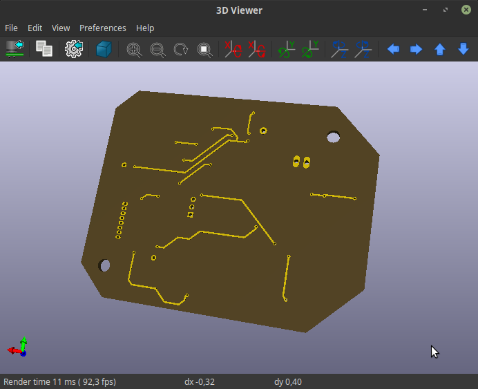
Then I moved to the PCB design section of the application, and I started ro route all the paths. There are many components, and To keep all the connection on just one side of the board was really impossible, so I decided to add some extra vias to the board, and move some of the paths on the bottom side of the PCB
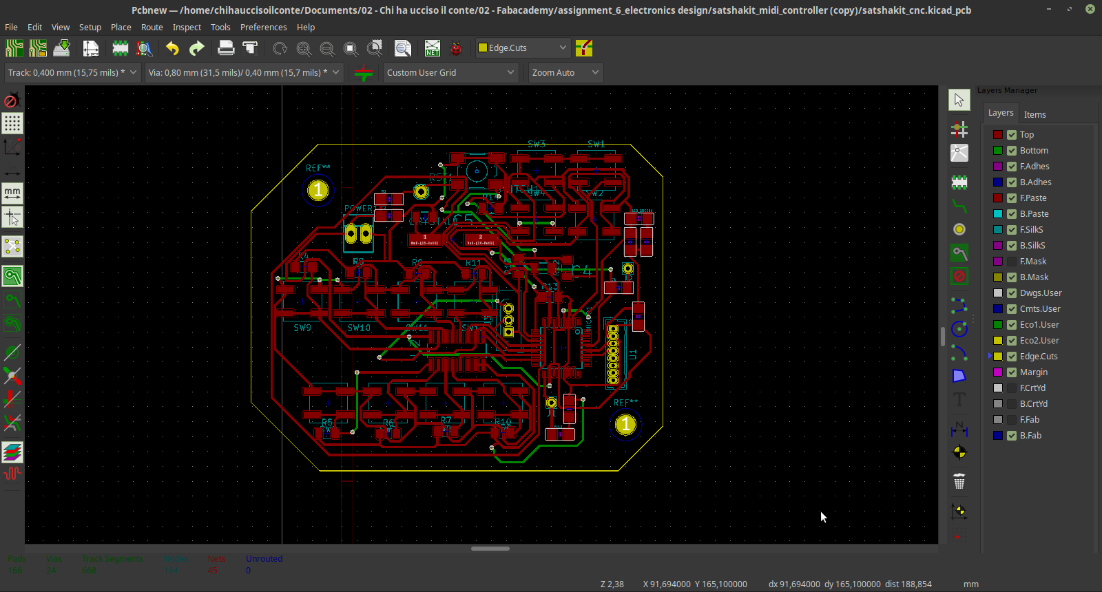
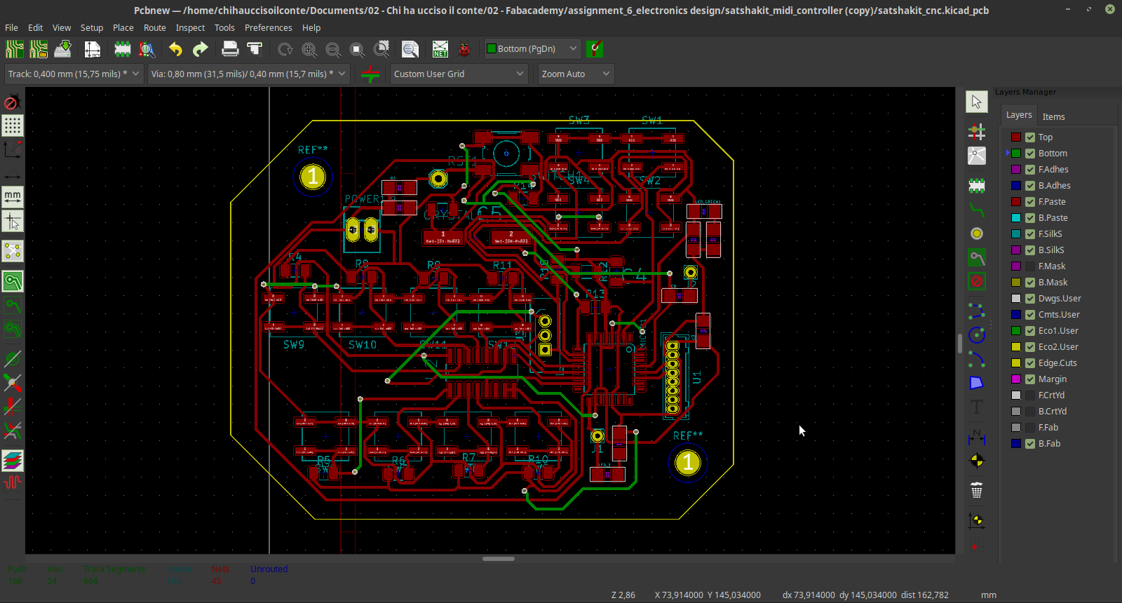
To use vias it's really great, but I tried to use them as less as possible, to keep a hypothetical milling of this circuit not too complex. However, KiCAD also have a very nice 3d viewer that allowed me to see at least a simulation of the circuit.
source files
Here are all the source files for the Input Devices assignment:
1 - code with gyro + MIDI
2 - code with gyro + buttons(MUX) + MIDI
2 - Kicad file of the board