Assigment #5
3D printing and scanning
The 5th assignmet of the Fabacademy it’s about 3d printing and scanning. To carry on this assignment I came back to my final project draft and to the 3D model I made for the CAD assignment. The object I’m going to make for my final project it’s a sort of “sandwitch” made out of two 3d printed shells and a wooden element in the middle. The shells I designed do have many undercuts that make them really hard to produce them with subtracting manufacturing, so I’m going to 3d print them and see what comes out of it.
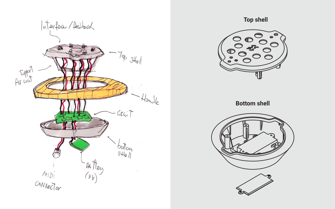
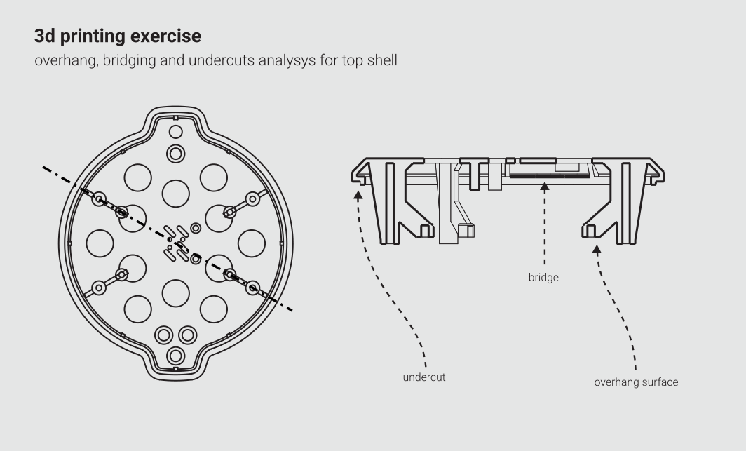
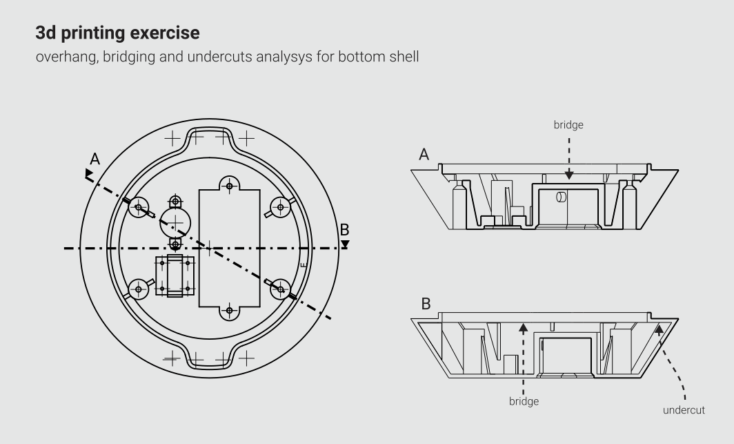
1 – sections of the design to test overhang, undercuts and bridging
The first thing I did was to print two of the models provided by Neil to test the capabilities of the printer I was going to use. The pieces I designed are quite big, and to 3d print them it’s going to take almost a full working day. Because of that I decided to prins some portions of them to experiment the most critical parts of them. However I tried to manage all this critical aspects in such a way that no support material is needed to 3d print what I need. The shapes I’m going to work with are based on rotational solids that create a sort of “nest” where all the components will be contained. This kinds of shapes presents very strong undercuts and overhanging surfaces. To turn the overhangs into a bridging surfaces I made a a polar array of vertical elements that sustain the top part of the solid. The supports for the pcb that will be installed inside the device are inclined in such a way that the machine should be able to handle it without any extra support materials.
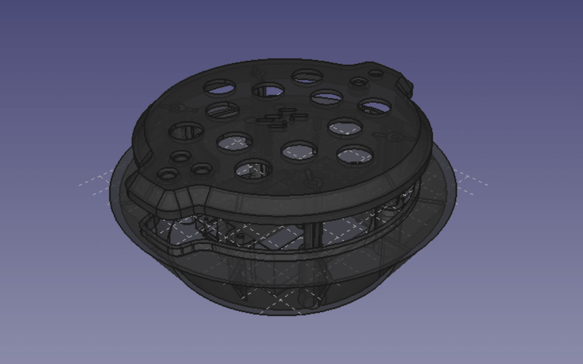
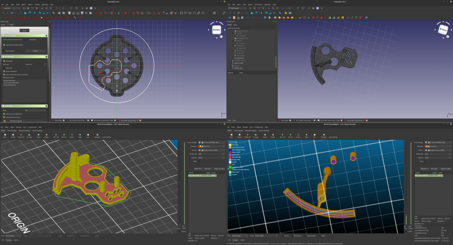
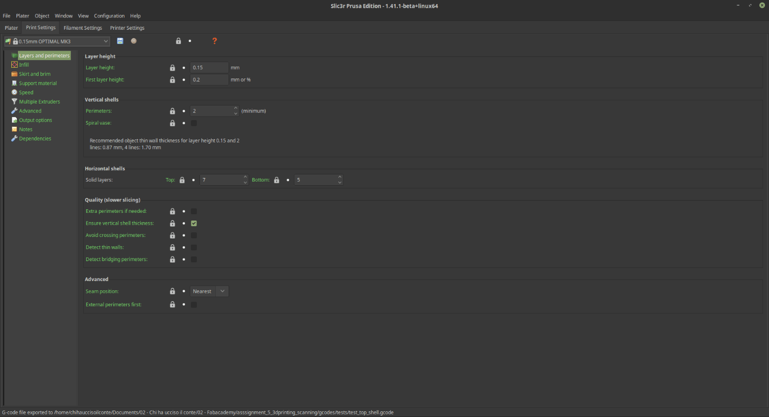
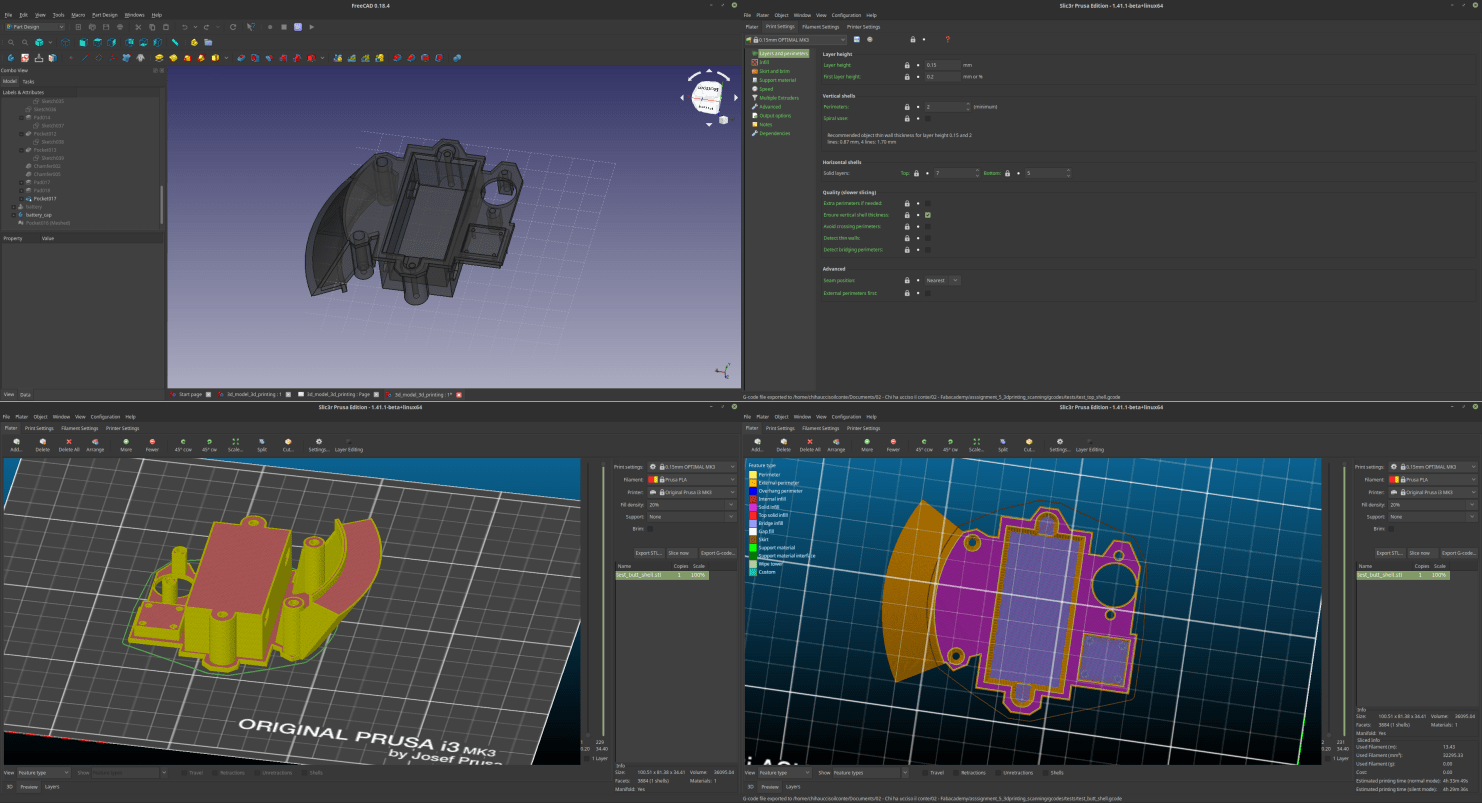
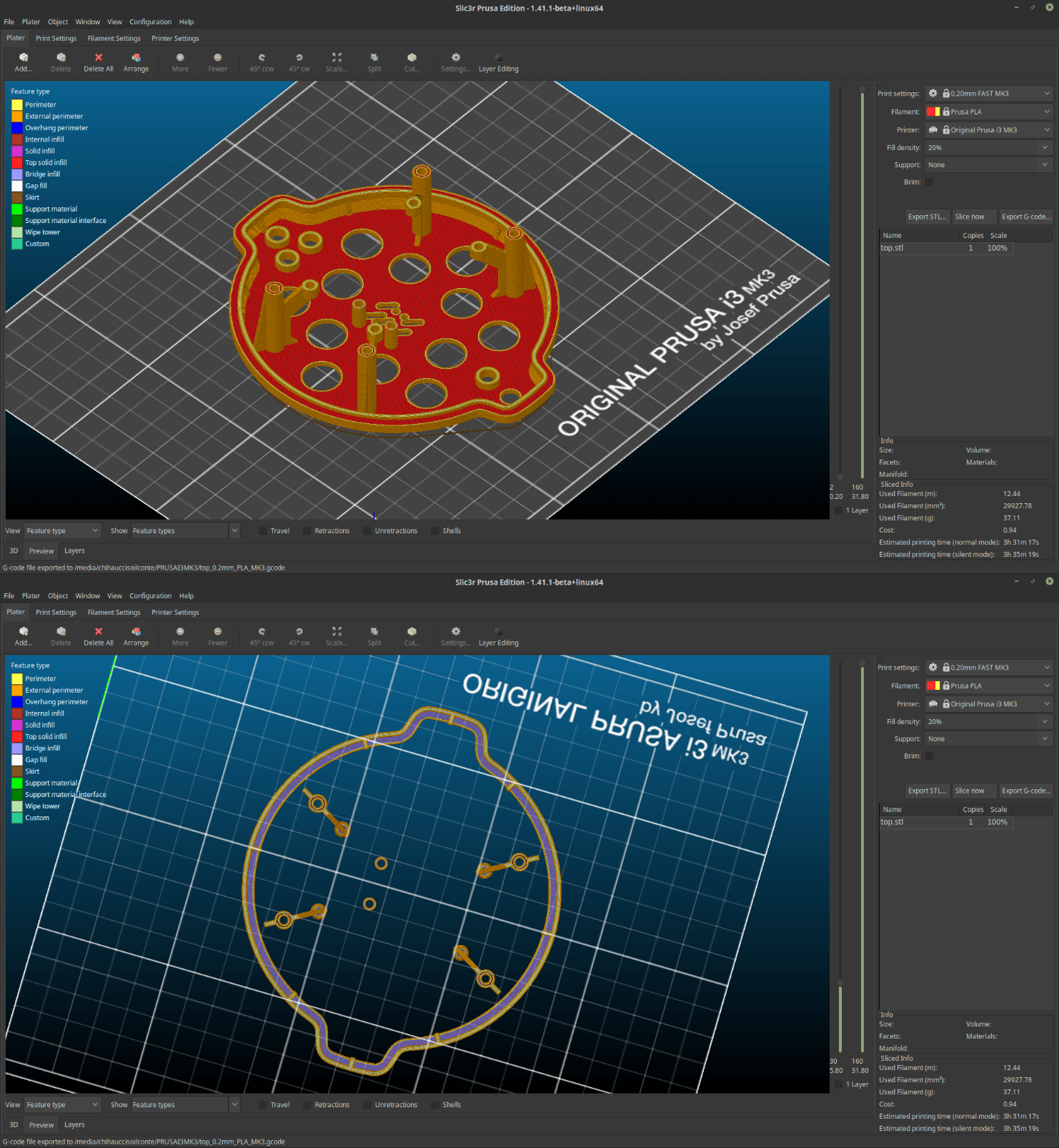
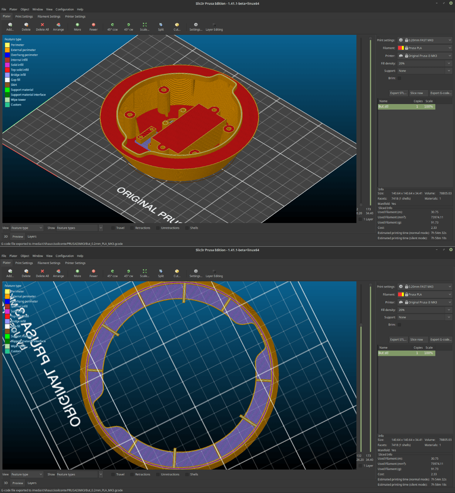
To test those assumptions I “sectioned” my design in parts so that I could print the most critical parts without wasting too much time and material. To do that I switched back to FreeCAD and used a sketch / pocket command and the exorted the parts obtained STL format. To slice the models I moved to Slicer prusa edition to take care of the postion and the rinting parameters of the machine. The slicer also allows me to test if my assumptions are correct. I can see through the colors in the visualization if my piece includes overhangs and bridging parts. The undercut that will suort the pcb its so inclined that its not even visualised as an overhang part and the slits I designed to suort the overganhing planes did their job because everything its visualises as a bridging plane. Im going to rint this part with a layer thickness of zero.fifteen mm which is a fine quality.
2 – 3D printing tests
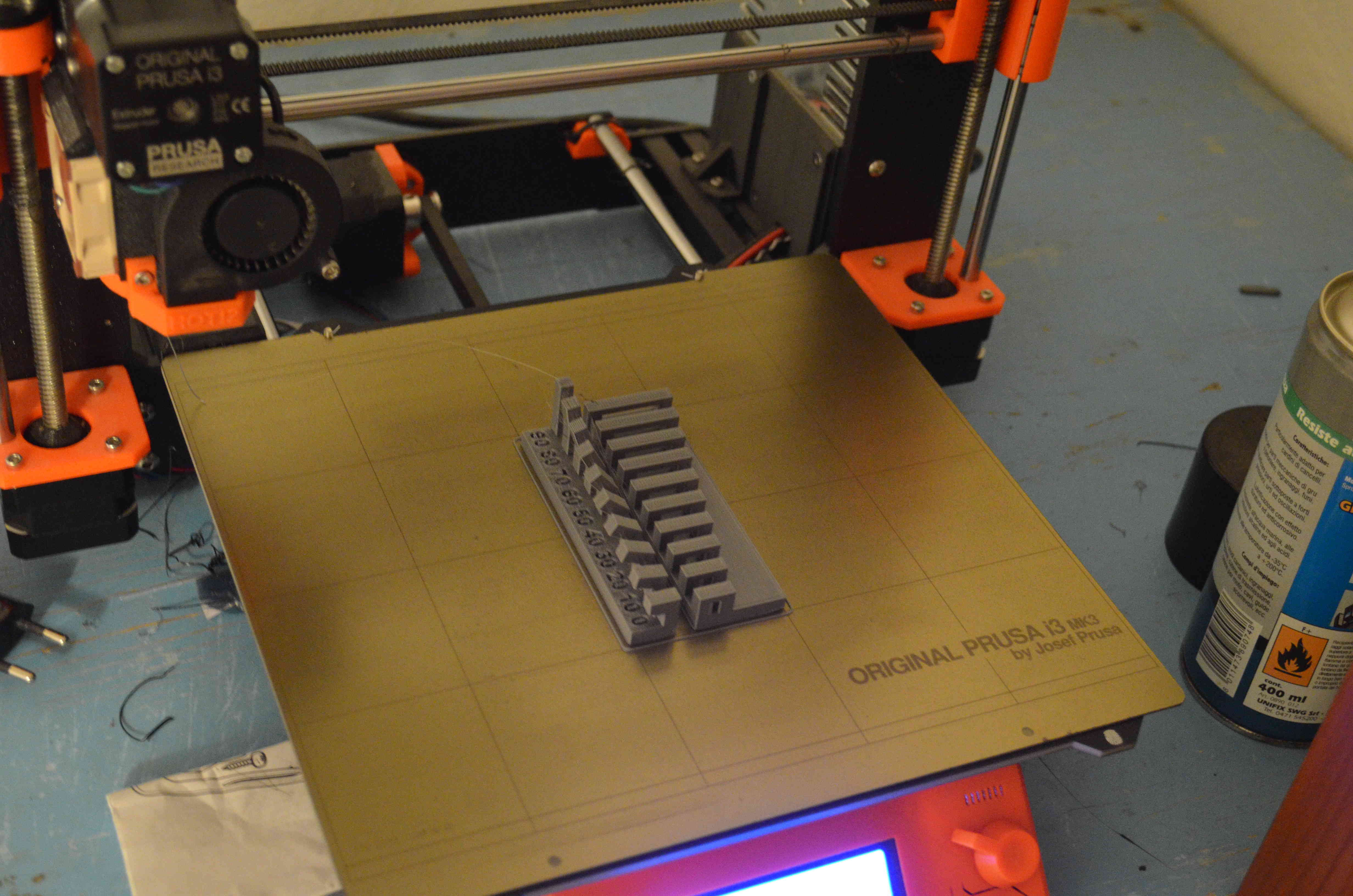
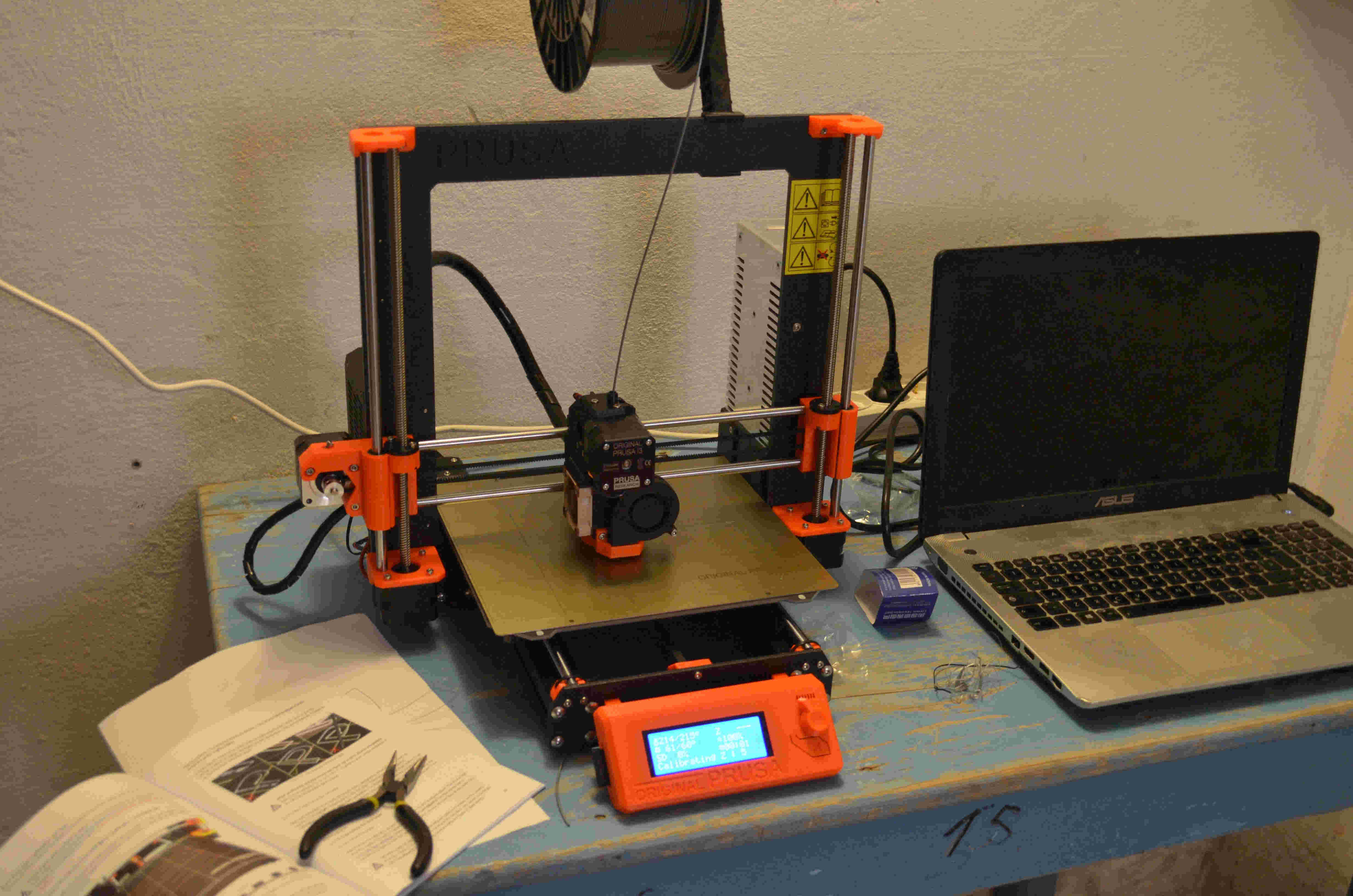
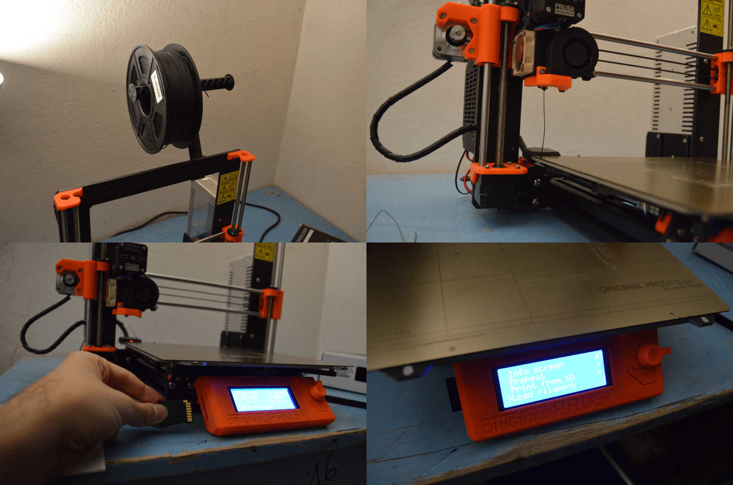
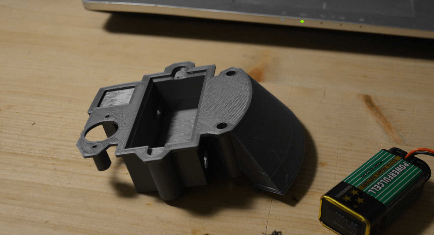
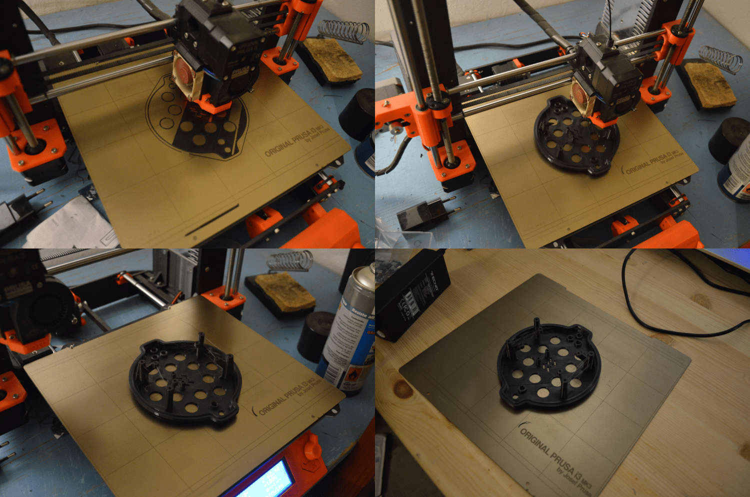
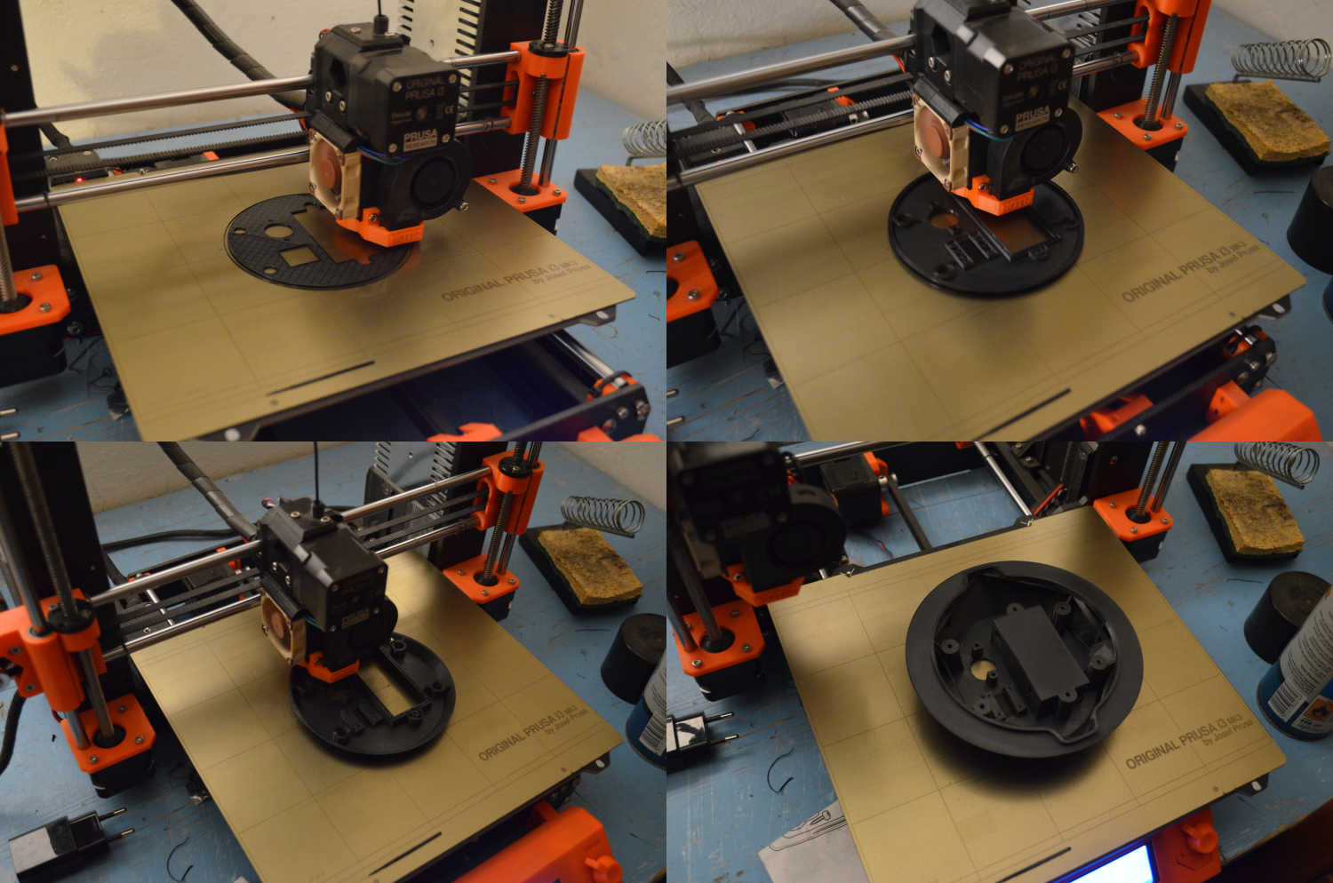
To slice the models I moved to Slicer prusa edition to take care of the postion and the rinting parameters of the machine. The slicer also allows me to test if my assumptions are correct. I can see through the colors in the visualization if my piece includes overhangs and bridging parts. The undercut that will suort the pcb its so inclined that its not even visualised as an overhang part and the slits I designed to suort the overganhing planes did their job because everything its visualises as a bridging plane. Im going to rint this part with a layer thickness of zero.fifteen mm which is a fine quality. Once my model is exorted into my sd cart I can finally approach the mnachine which is a badass prusa i3 mk3. The first thing to do its to lload the filament. in my case pla I preheat the extruder to 215 degrees and I gently accompany the filament inside the extruder so that it takes smoothly the material. Once this is done I insert my SD card containing the gcode I just made with Slic3r. The machine starts to move and it uses his "pinda" sensor to detect the exact position of the building plate. then it starts to build my iece layer after layer... The printing went really well. the piece looks nice and the overhanging surface that will kee the pcb its erfectly smooth. The bridging also went well I must not that dued tothe fact that the perimeter of the surface is circular some of the filament did not stick as lanned anb theres a bit of "spaghetti" in the inner part of the piece. The plane its trong and steady anyway and Im sure the world has seen worse, so, I think I can consider this a success.
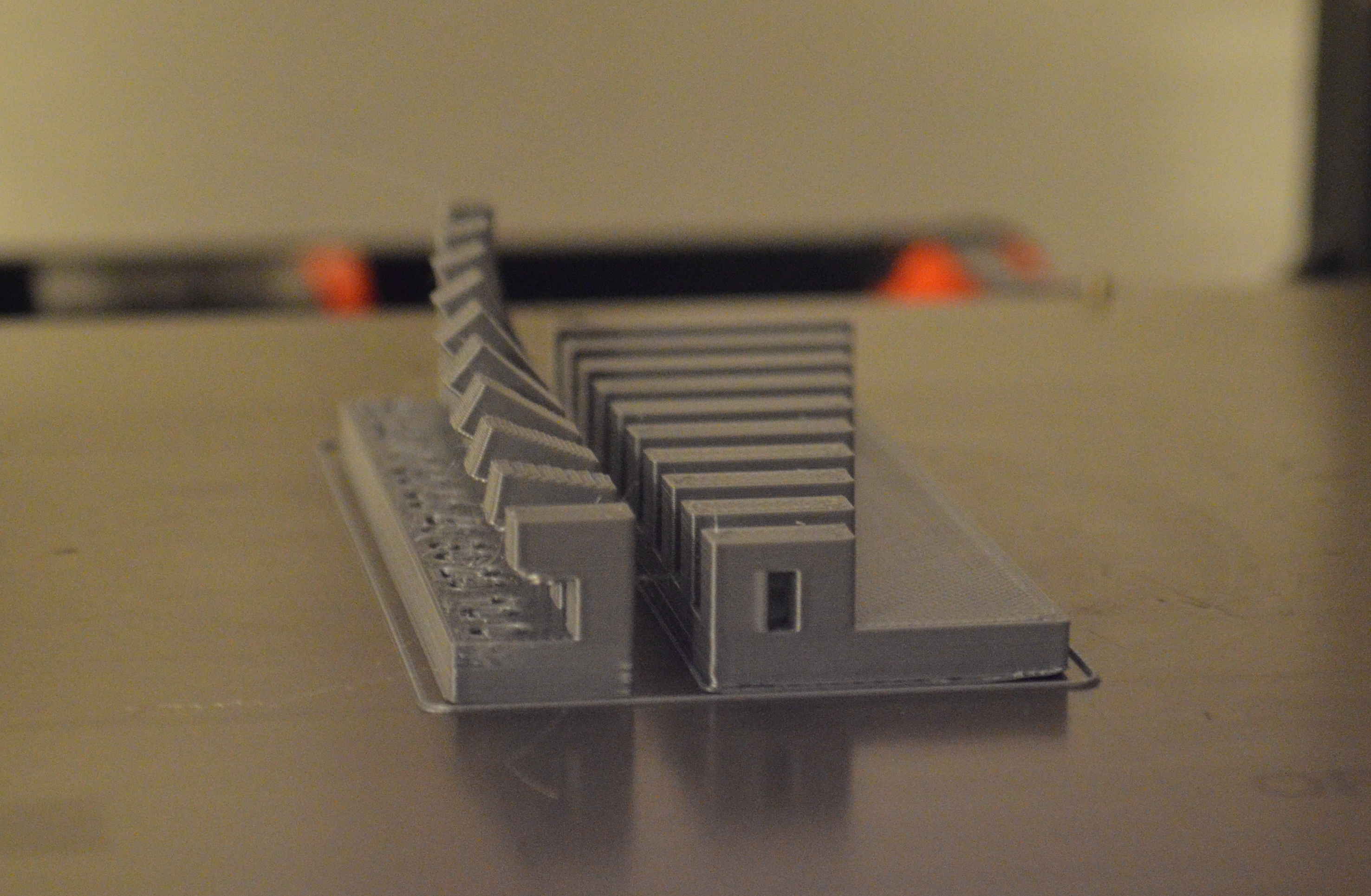
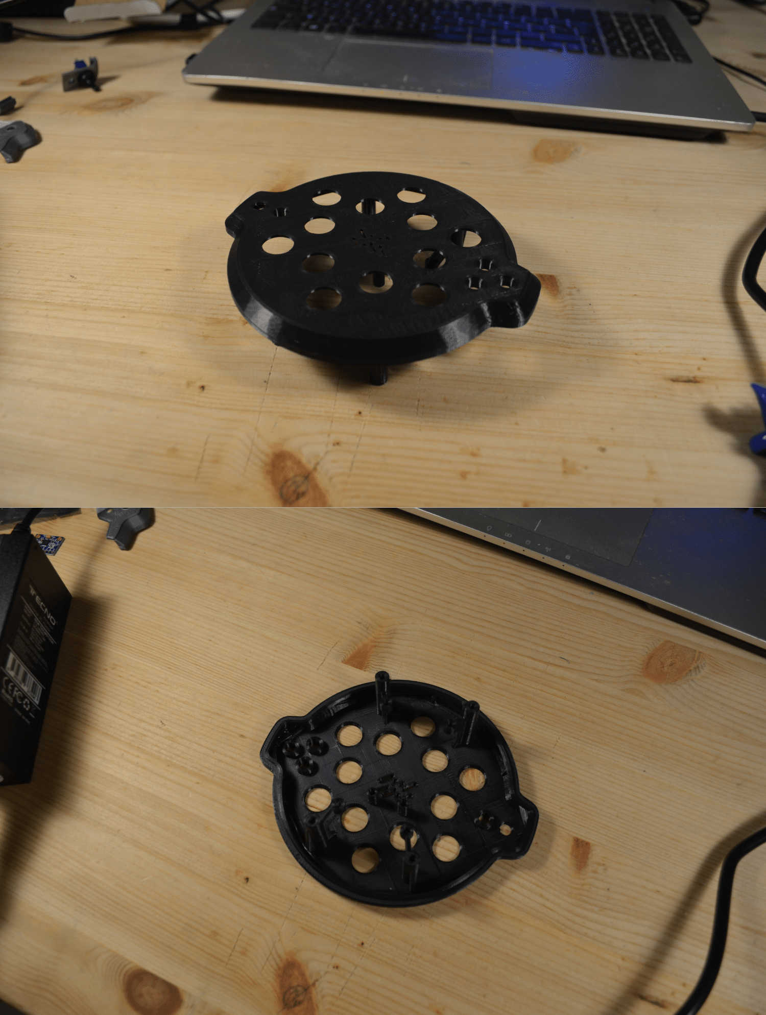
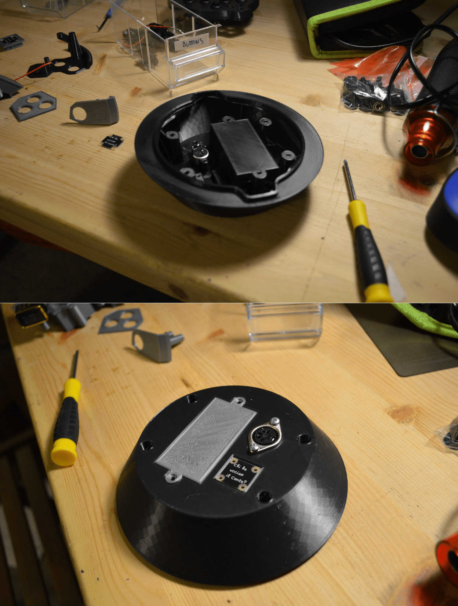
Nest step its going to print a section of the lower shell too wich contains a big bridging area that is the bottom of the battery case + a hole for the MIDI socket and a little frame to contain a tag that I would like to attach to my controller. I feel like mentioning that in this shelll there will be some holes that are not touching the printing surface which could turn in a quite bad thing. to do that I extruded a little plane on to of those trichy elements in this way I turned those overhanging perimeters into a bridging surface that will be handable by the machine and smashed very easily by the screws that willl go inside the comonent I followed the same process I did with the upper shell anb also this print gave me good results (still some little problems in the bridging erimetral area but nothing terrible...)
3 –sections of the design to test if the comonents will fit
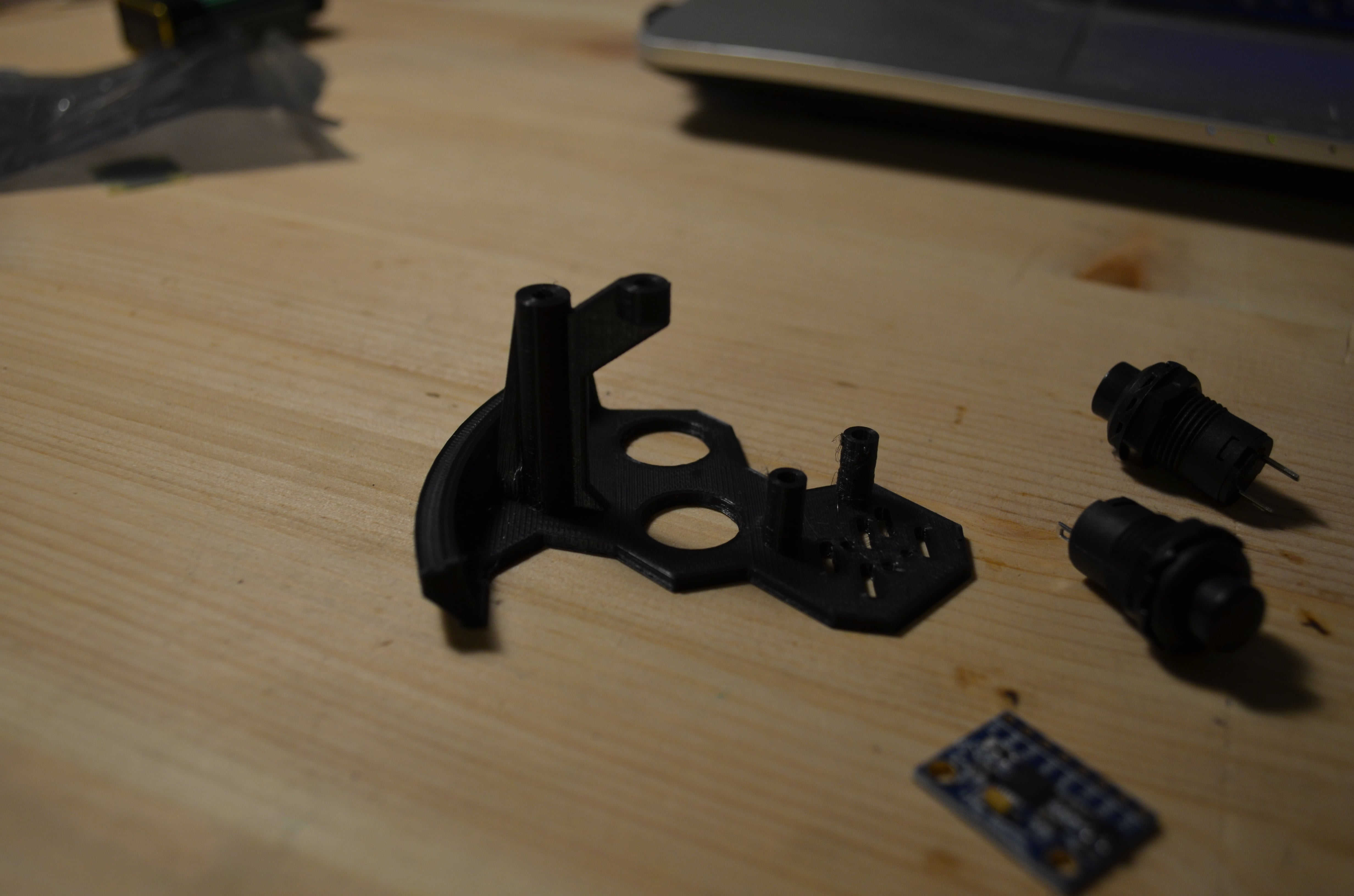
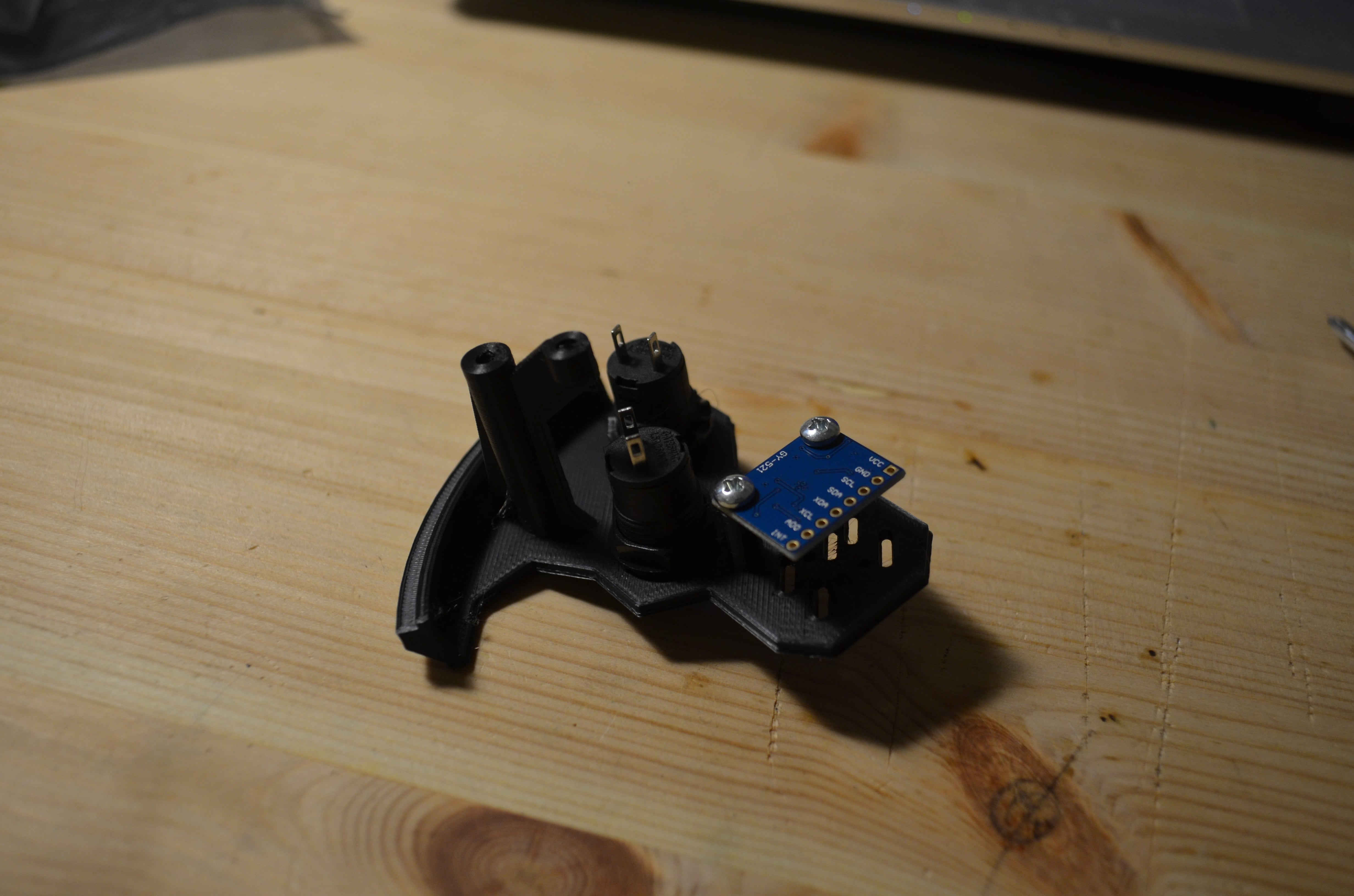
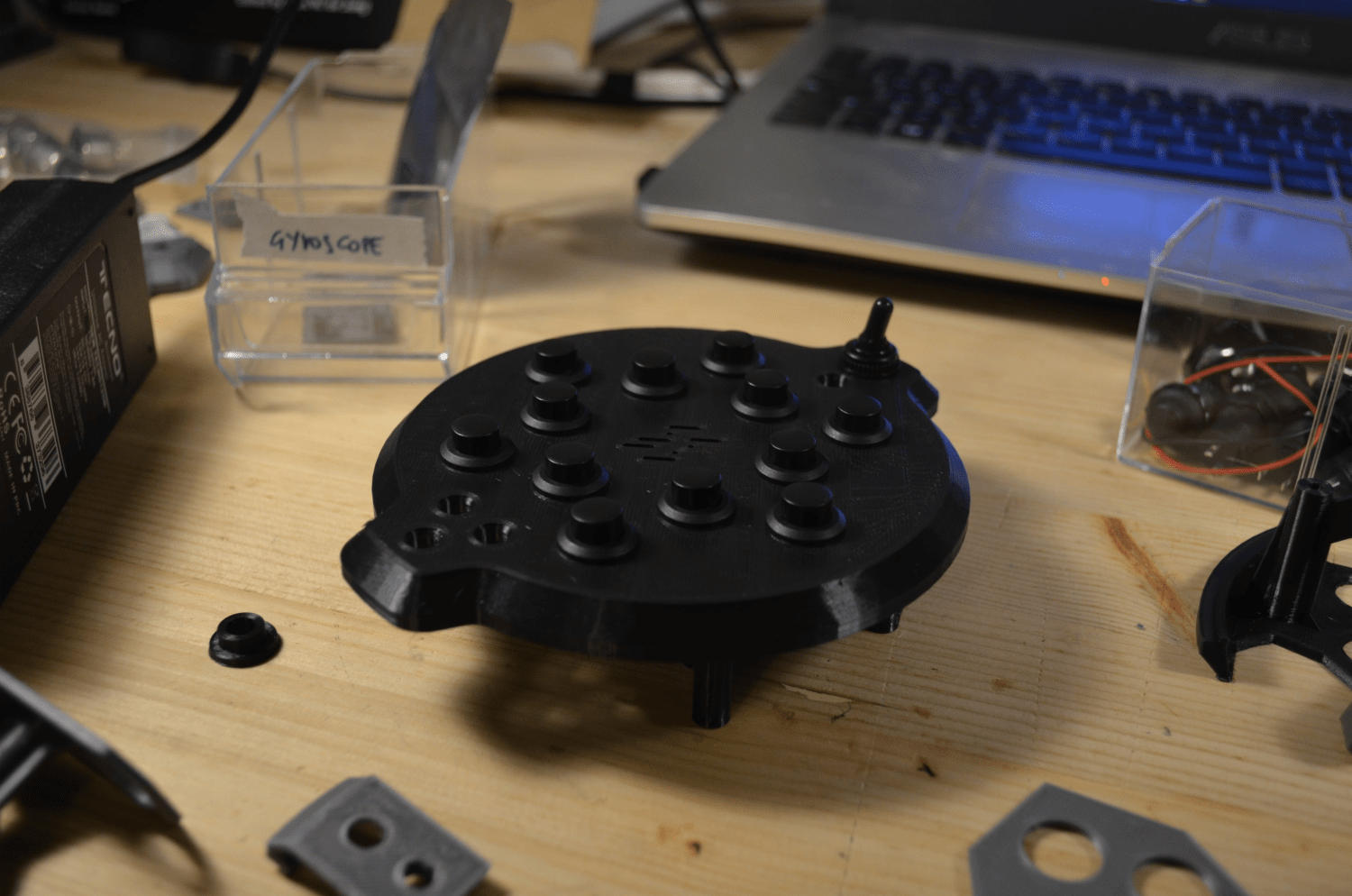
Next test I did was to check if the parts that I’ll need to make my final project work will fit in the parts I designed. So, I took the buttons, the battery, the accelerometer, the MIDI socket and the tag to see if everything worked and the answer was affermative in almost every case eccept for the tag, and (ouch...) the distance between the circuit support and the lower shell. I noticed that this distance was almost zero which will tur into a non-fitting circuit...
So I came back to FreeCAD and fixed those problems and I also made some more STL files to test other components like LEDs and the switch.
After a littke bit of ping-pong I managed to make everything fitat perfectly!
3d print the whole shells
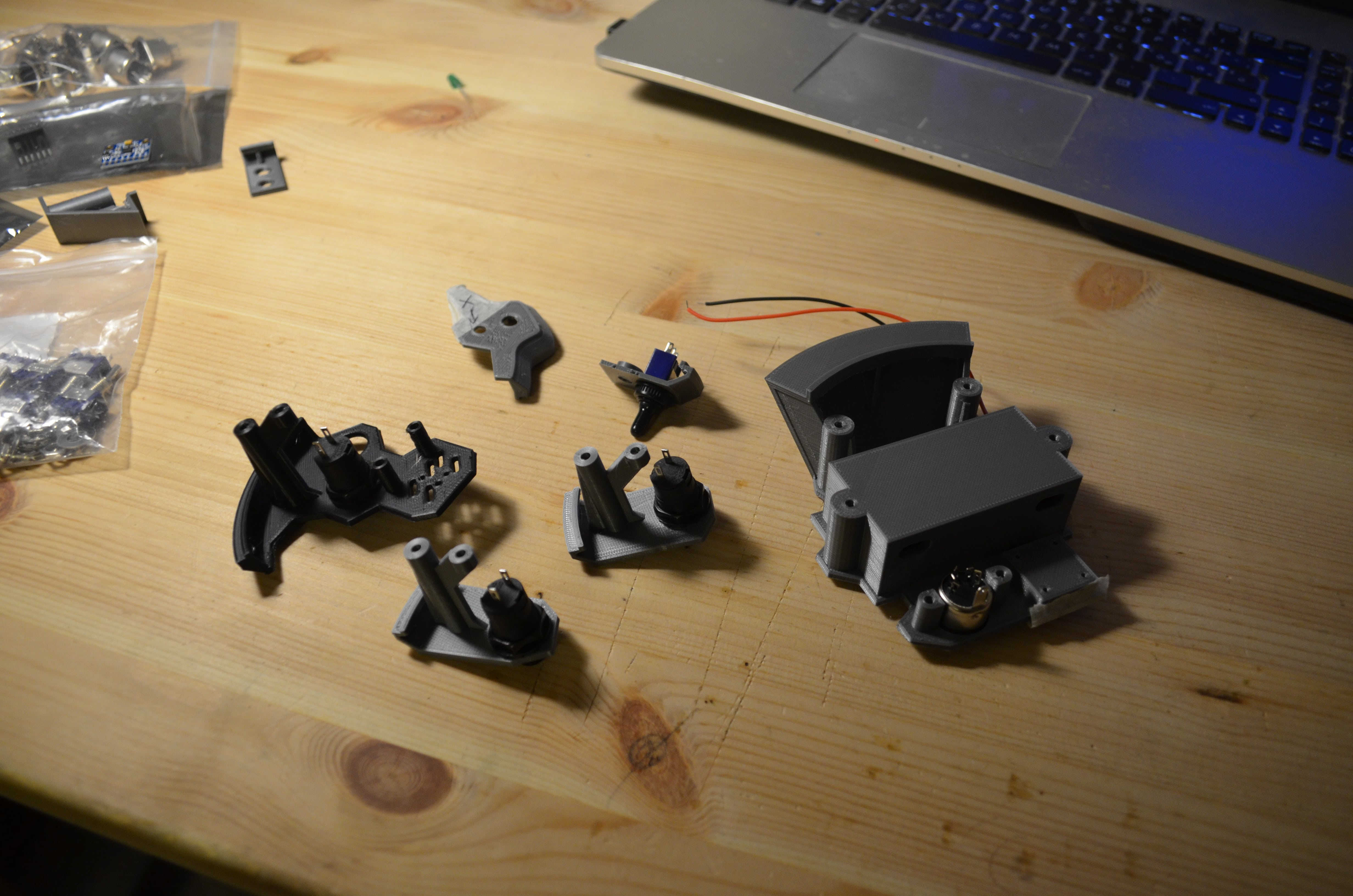
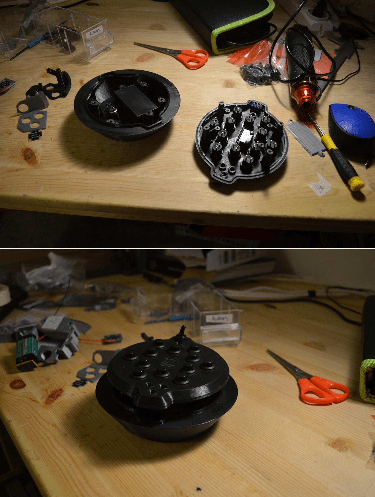
Last art of my assignment was to finally rint the whole parts so I exorted them from freeCAD and printed them comnletely. Since the parts were big I was a little nervous about it but I was also confident in the test I made.
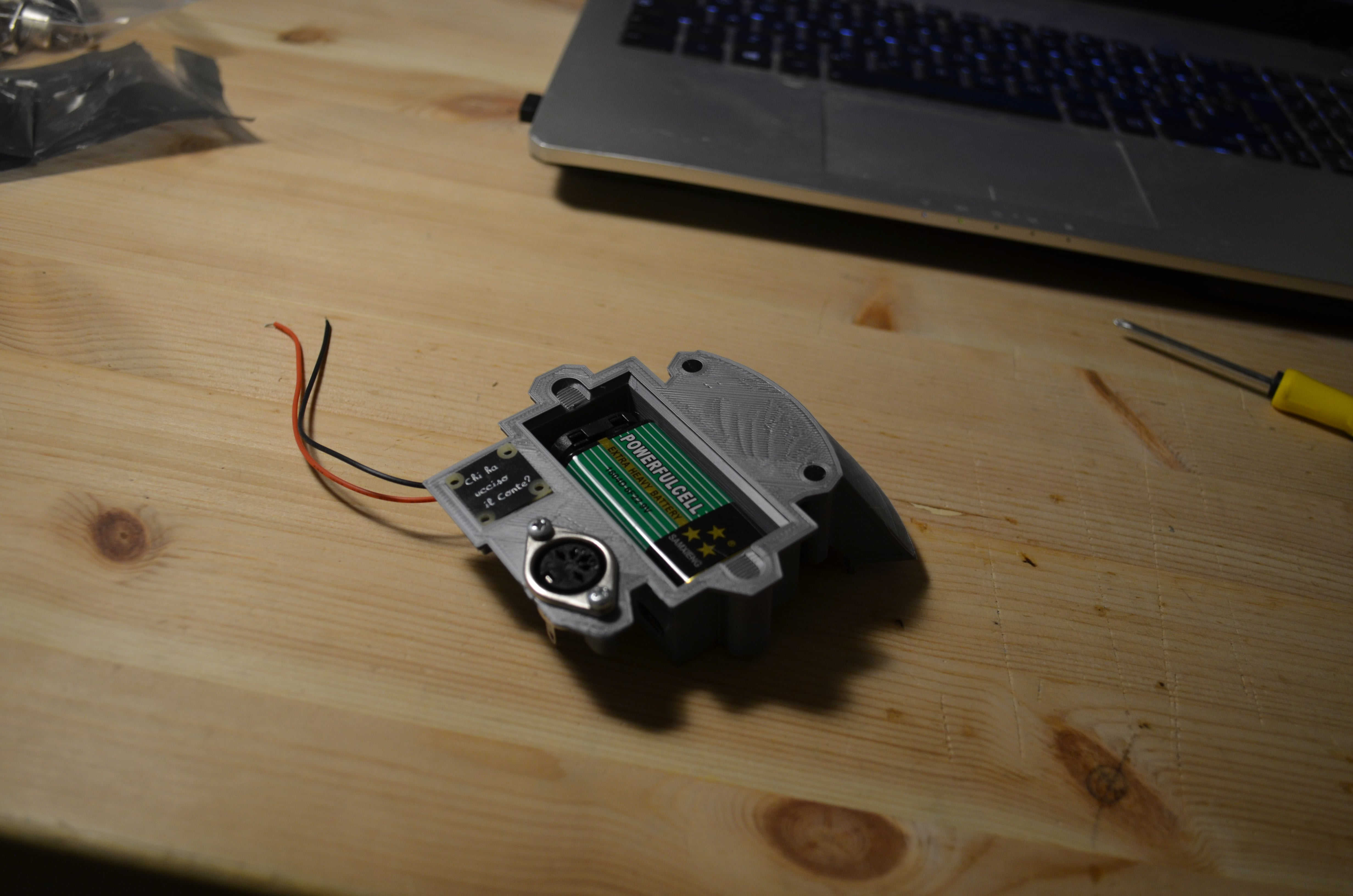
In the upper part there was a little bit of oozing which is a very thin filament that goes all over the part. it is ossible to fix that by just blasting hot air around the piece with a heating gun however this is a symtom of the fact that the ressure of my extruder its too high and that is probably dued to a nozzle that is too close to the printing surface so I re-calibrated the machine and went for the bottom shell which came out perfectly.
Last thing I did was to place the comonents into my shells ands Im very happy with what I had in my hands at the end of the process.
4 - 3D scanning
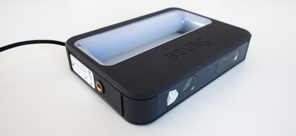
Arter modeling and printing all this stuff it is time to share some 3D scanning experience. I used a sense 2 3D scanner to scan my friend and collaborator Jon.
The 3D scanner comes with a software on it's own that allowes you to scanning a volume by passing the scanner around it.
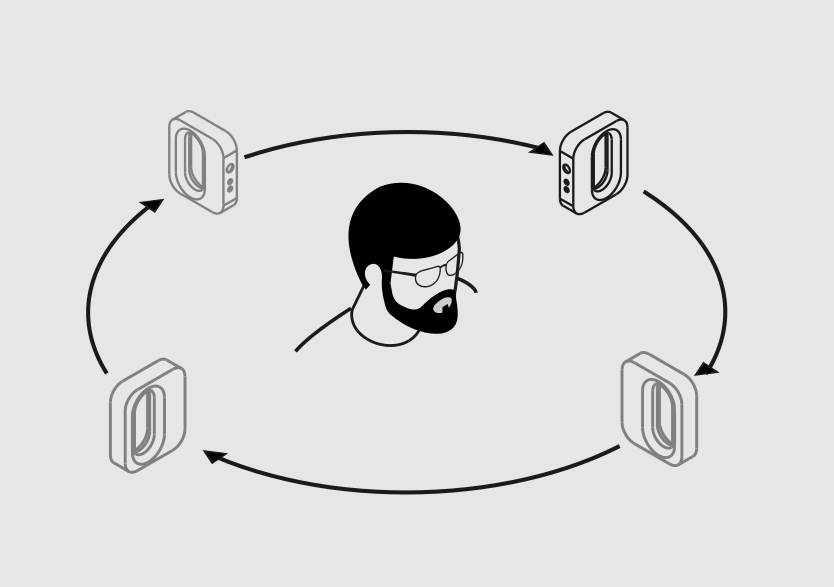
This process is quite simple, but It took a bit of practice before we could successfully scan an object, that is because it is very important to keep your hand steady and move smoothly.
The principle is very simple in theory, the scanned object needs to stand, and the scanner needs to turn around it, In practice it's a lot more complicated...
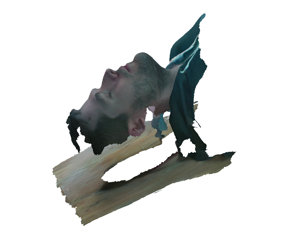
 After a few atempts we managed to get a good scan of Jons face.
The outcome that the machine provides can be exported in STL or in OBJ format. We went for this second solution because OBJ is a format that includes color in it, which makes the 3D model a lot more realistic.
Both, STL and OBJ are mesh 3D models, which means that they are made out of poligons connected together. Its' a very heavy kind of format in comparison with curve based 3d models (such as 3DM or STEP), and you need specific tools to work with those, like 3dstudiomax, maya or Blender.
So, I imported it in Blender to clean the mech and to give a thickness to it (using the modifier for that)
After a few atempts we managed to get a good scan of Jons face.
The outcome that the machine provides can be exported in STL or in OBJ format. We went for this second solution because OBJ is a format that includes color in it, which makes the 3D model a lot more realistic.
Both, STL and OBJ are mesh 3D models, which means that they are made out of poligons connected together. Its' a very heavy kind of format in comparison with curve based 3d models (such as 3DM or STEP), and you need specific tools to work with those, like 3dstudiomax, maya or Blender.
So, I imported it in Blender to clean the mech and to give a thickness to it (using the modifier for that)
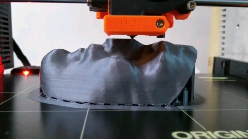
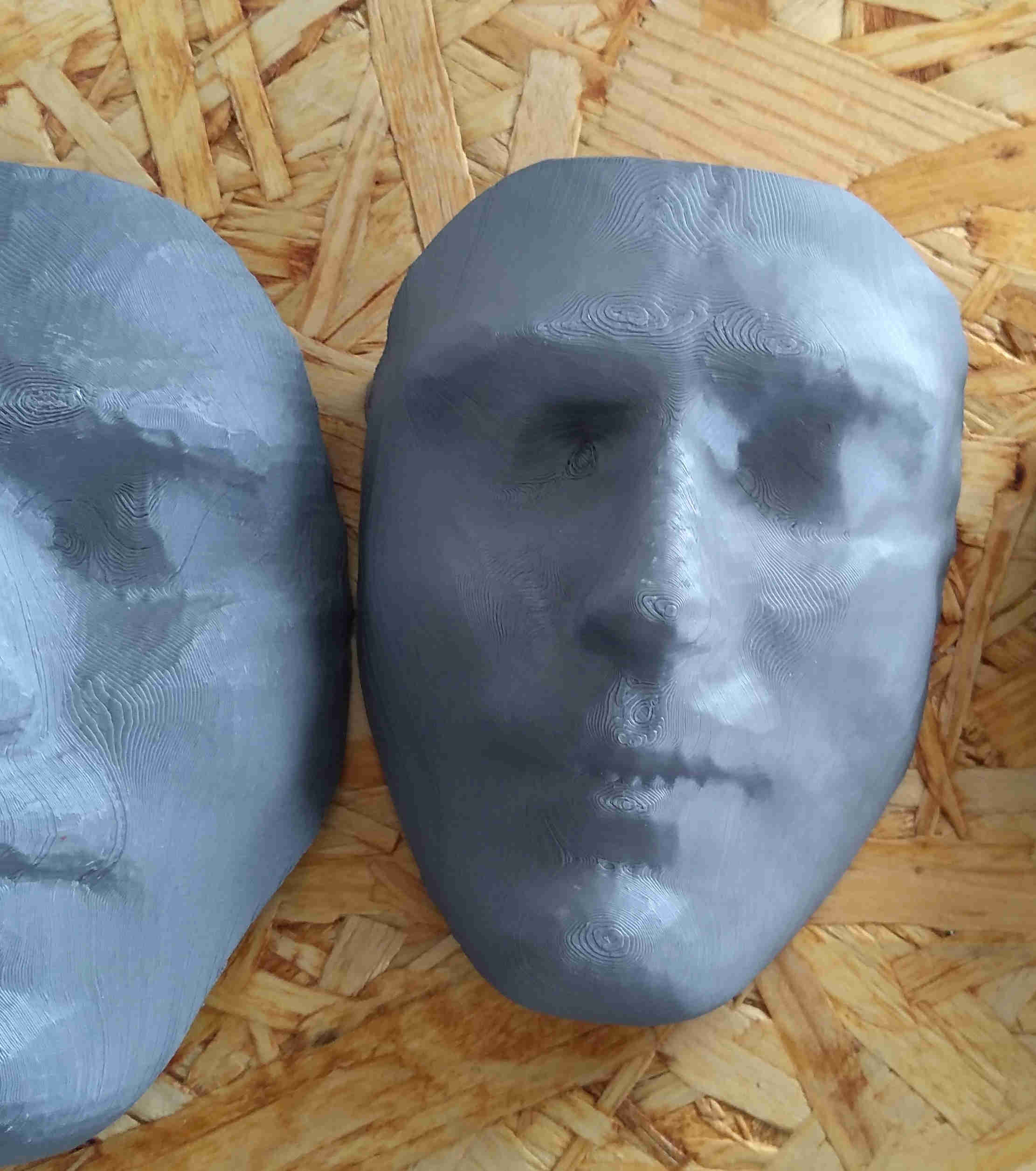
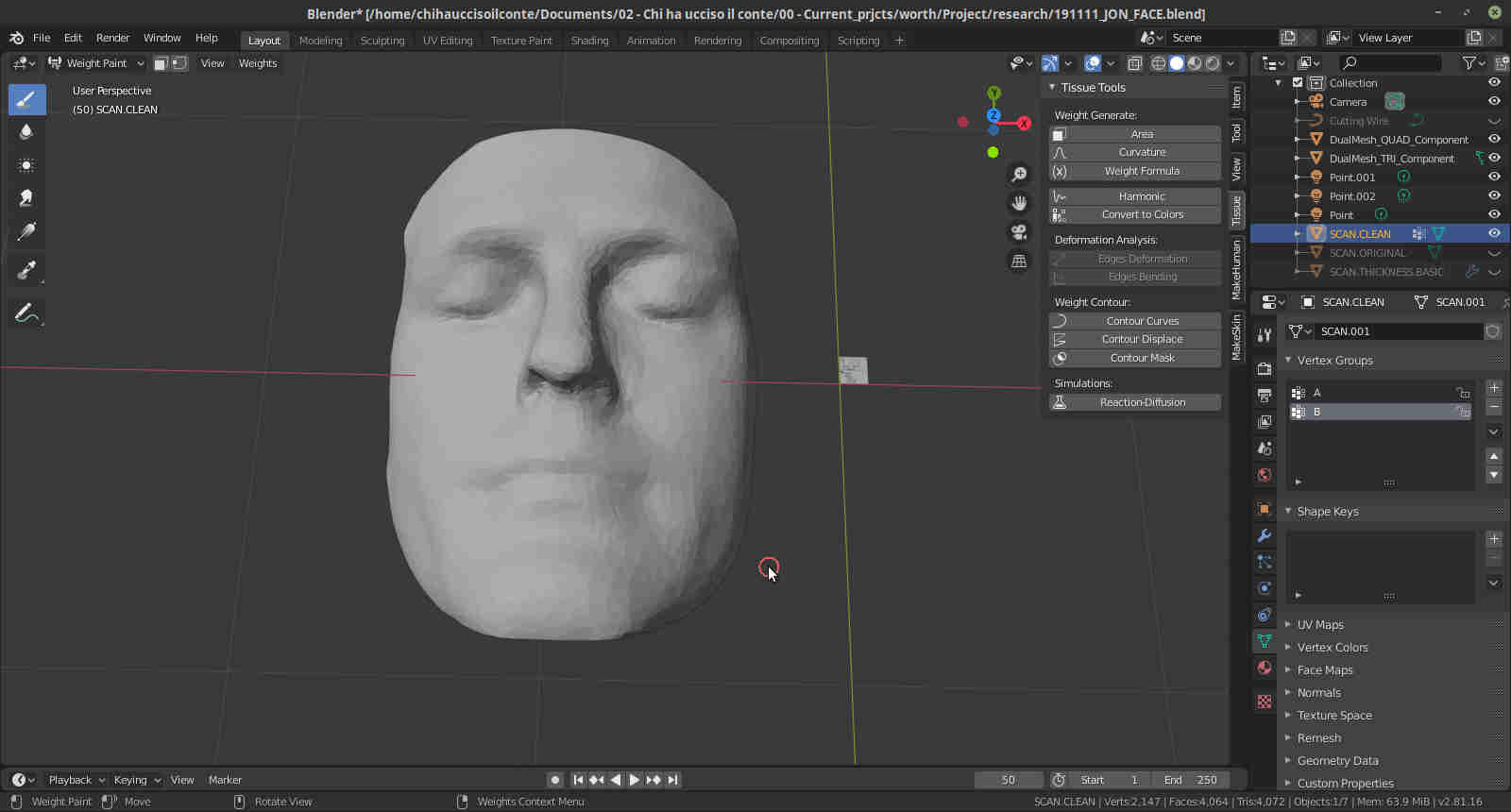 Once this operation was complete I exported the file in STL and 3d printed it too, like a mask
5 - considerations and takeaways
So this assignment went quite smoothly, as usual we can be sure that the gods wont feel challenged by the perfection of my work, and I probably need to make some tests about the bridging surfaces that went wrong, but once again. the results were very satisfing and I cant wait to make the rest of my final project...
I feel like mentioning that the graphics and the sections I made to explain the critical aspects of the designs are made with the "Techdraw" workbench of FreeCAD + the usual inkscape
source files
Here are all the source files for the 3D printing assignment:
1 – Top shell STL
2 – Bottom shell STL
3 – Full 3D model - FreeCAD
4 – Jon Face - Blender
5 – Jon Face - STL