Assigment #2
CAD
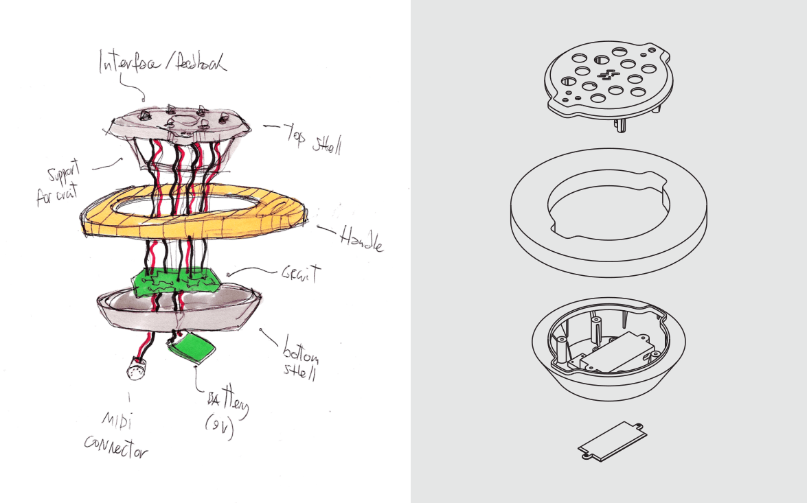
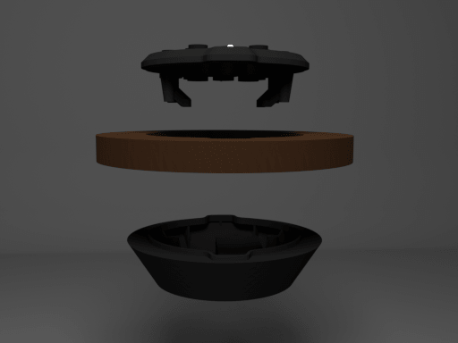
The second assignment of the Fab Academy program is focused on CAD, we have to turn the sketch from last week into a 3d model. Before starting my 3d modeling work, I gathered some components that I’ll use to make my final project, specifically, a gyroscope, some buttons, a MIDI socket, some LEDs and a battery. I’ll keep the dimensions of those parts in mind while I design every aspects of the controller, together with a hypothetical circuit that it’s still do be defined.
0 – My ally is the Source, and a powerful ally it is.
The first Thing I did to achieve this task it’s been to choose the best software(s) to go through all the necessary steps. After a brief exploration of some of the software mentioned by Neil during his lesson. The choice at the end was oriented towards the use of open-source software. This choice is given by ethical reasons (I’m really into open source tools) as well as performative qualities of the applications selected, plus the possibility to easily switch from a software to another that it’s not always easy to do when you use proprietary software To be more specific, I used FreeCAD to 3d model the volumes, Inkscape to design some of the details of my design and some documentation materials, and Blender to render and animate this 3d draft.
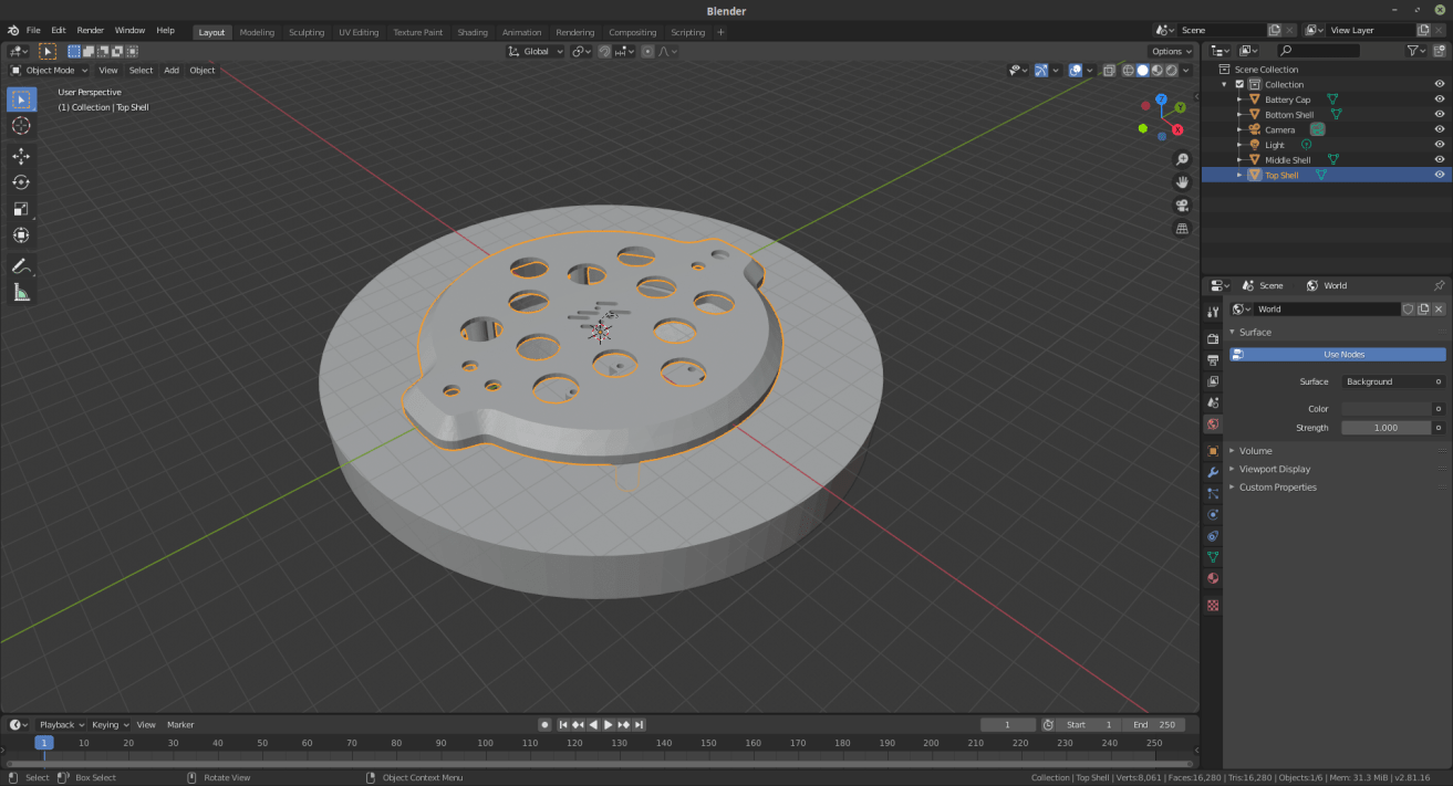
1 – 3D - Main volume for the top-shell
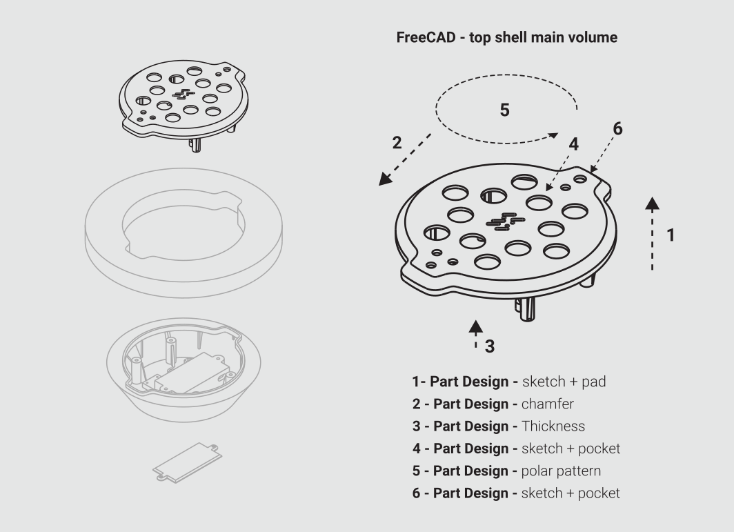
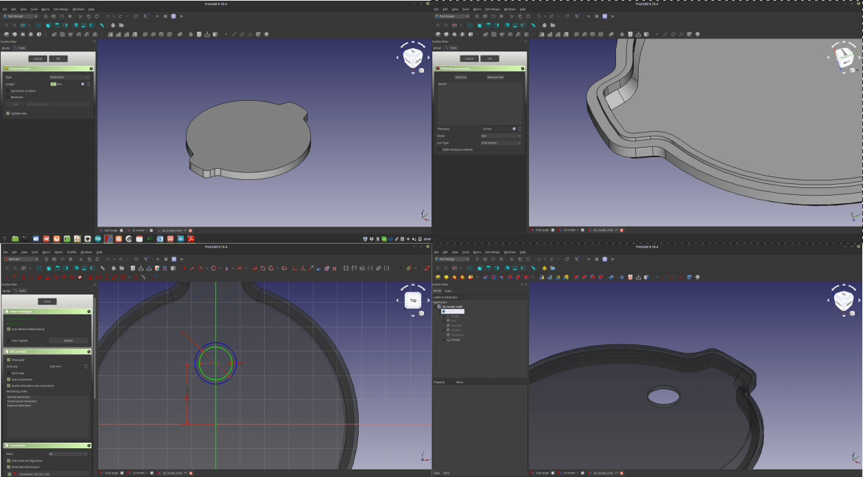
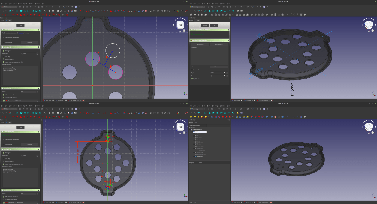
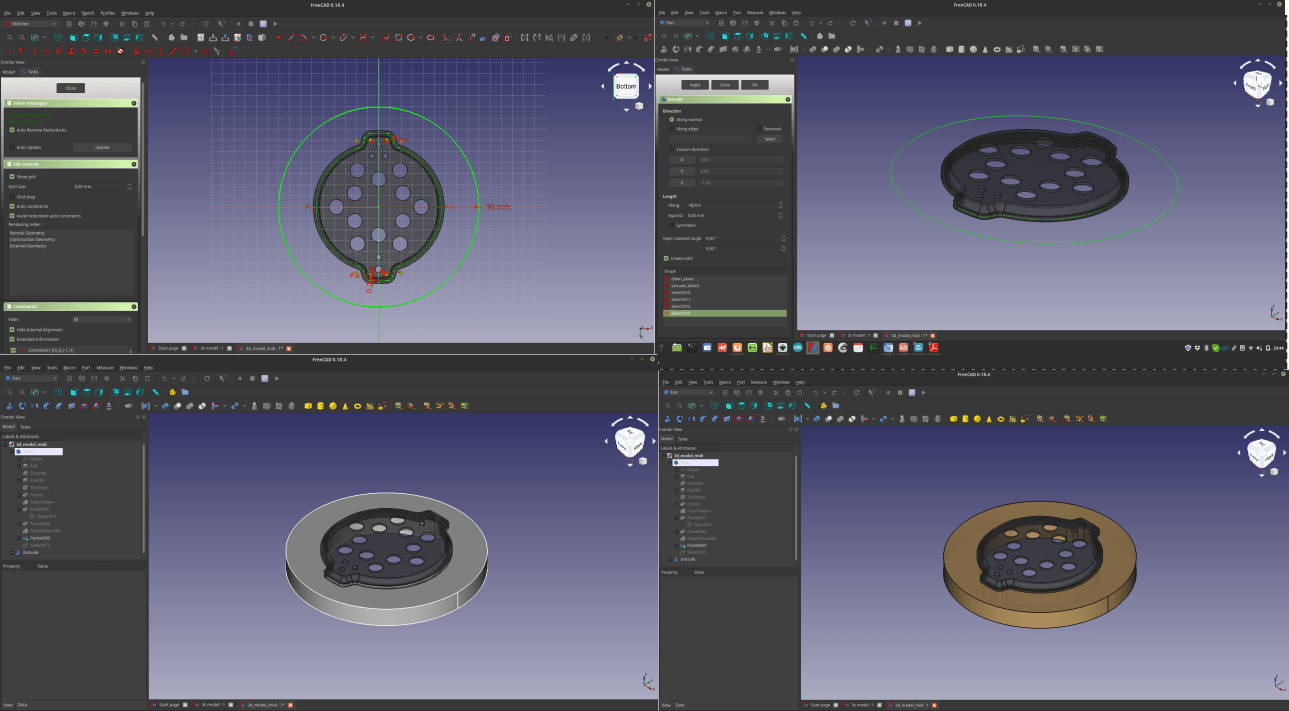
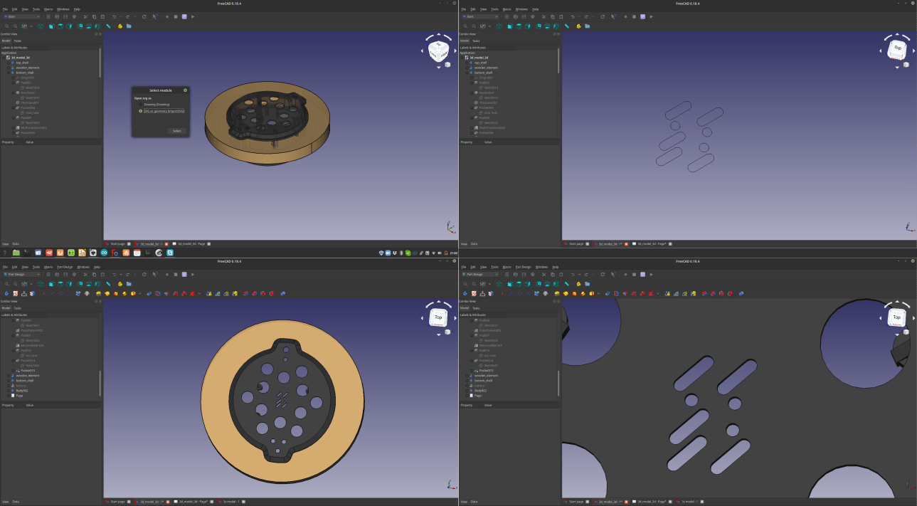
So, the first part I designed was the top shell that will be the top of my “sandwich-shaped” MIDI controller. To do that I used many tools that are inside the FreeCAD “Part Design” workbench: The first thing I did was to create a new part, draw a sketch and then extrude it, using the “pad” command, and repeated to add an element that will go inside the wooden element. Then I used a Chamfer command to smooth the upper part of it, and I applied a thickness to the whole volume Once this was done I used a thickness command, and a sketch + pocket to generate the holes where the buttons will fit. After that I used a Polar Pattern to repeat the holes for 6 times. I made this operation twice to reach the number of 12 holes (as many as the buttons I would like to have in my controller), and again a a sketch + pocket to generate holes for LEDs and switch.
2 – 3D - Middle wooden element
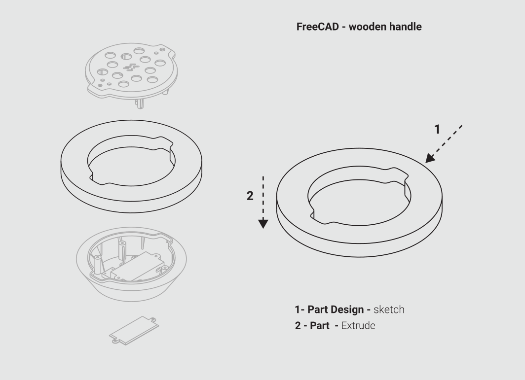
Now that at least the main volume of the top shell it’s complete, it is time to make the middle element that will be held by the user. To do that I made a sketch, and then instead of using the Pad command, I switched to the Part workbench, and used an extrude command to add a thickness to my sketch. In this way the software generate a solid that is not integrated into the part I previously generated, but a new independent component. After changing the color and the transparency of this element I moved to the next part
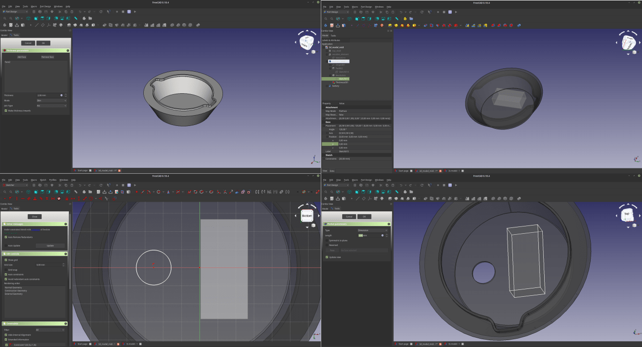
3 – 3D - Bottom shell mail volume
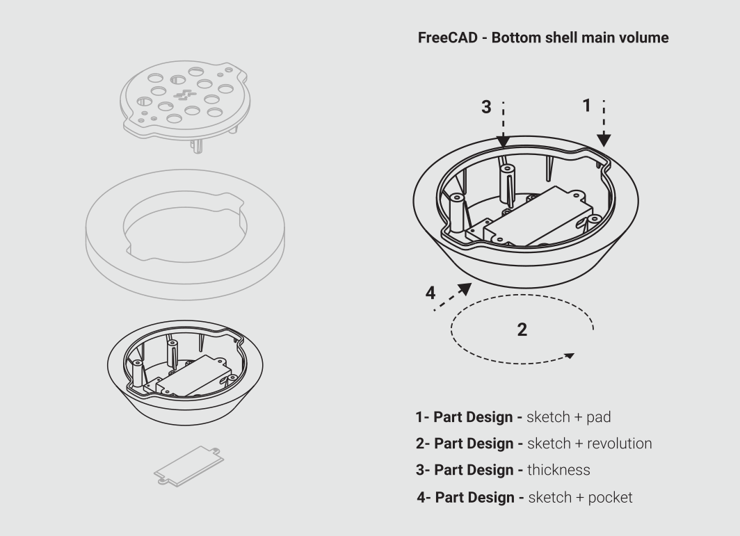
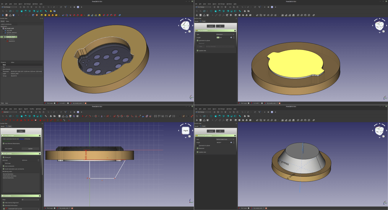
Now it’s time to design the bottom shell of the device, that will contain the battery, the MIDI socket and a tag to mark the device with my name. To do that, I start by creating a new part, and then drawing a sketch. I pad the sketch in such a way that goes inside the wooden element, and sticks a little out. After that I draw a new sketch that will be the profile of the shell, making sure there’s an intersection between the upper side of the sketch and the pad previously made. At this point I select the sketch and I make a revolution command to generate a rotational solid. I apply a thickness to the volume to make it an empty shell. Then I make a small solid that will represent the battery. In this way I can see if the shell I made, and if it’s not big enough I can edit the revolved sketch to fit it. Last thing to do at this point is to dig a hole for the MIDI socket. I draw a circular sketch at the end of the volume I’m working on, and use a pocket command to make a hole in it.
Now that I have all the 3 volumes, I can start to work on the elements that will connect them.
4 - 3D - Top shell details
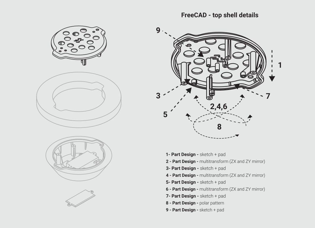
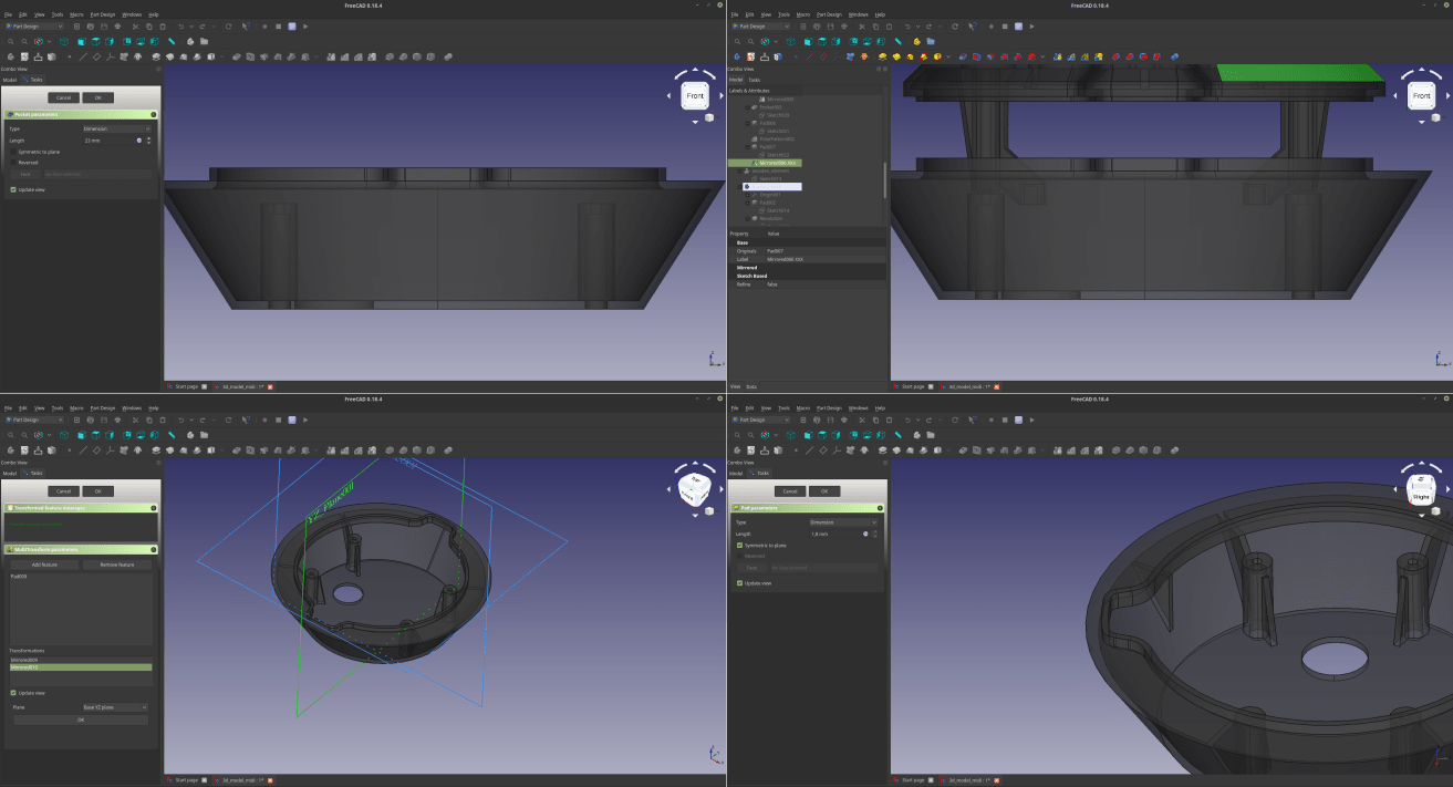
I extruded a column at the bottom of the top shell that will work as a connection with the bottom shell. To do that I used a sketch + pad command. Then I used a multiple feature to mirror twice this element, and I repeated this process for the PCB supports and for some supports that together with the circular array of a little slit, will strengthen the shell. Last thing was to add another element to attach the gyroscope.
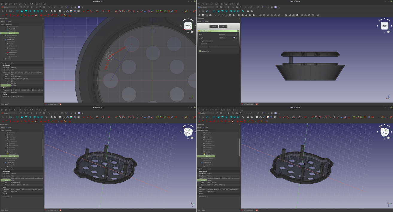
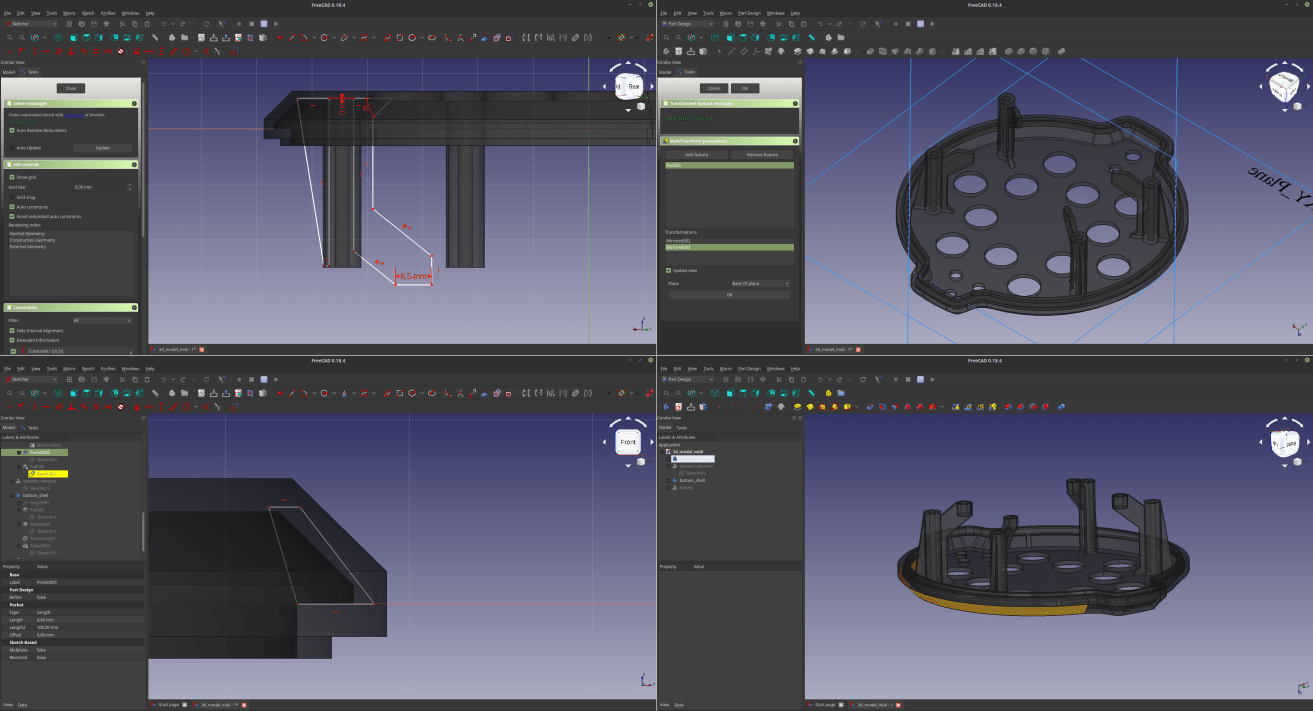
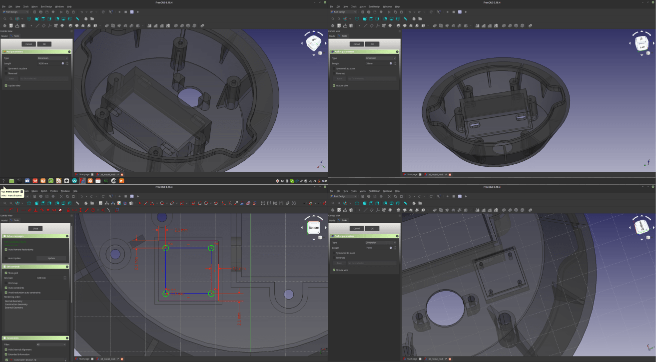
5 - 3D - Bottom shell details
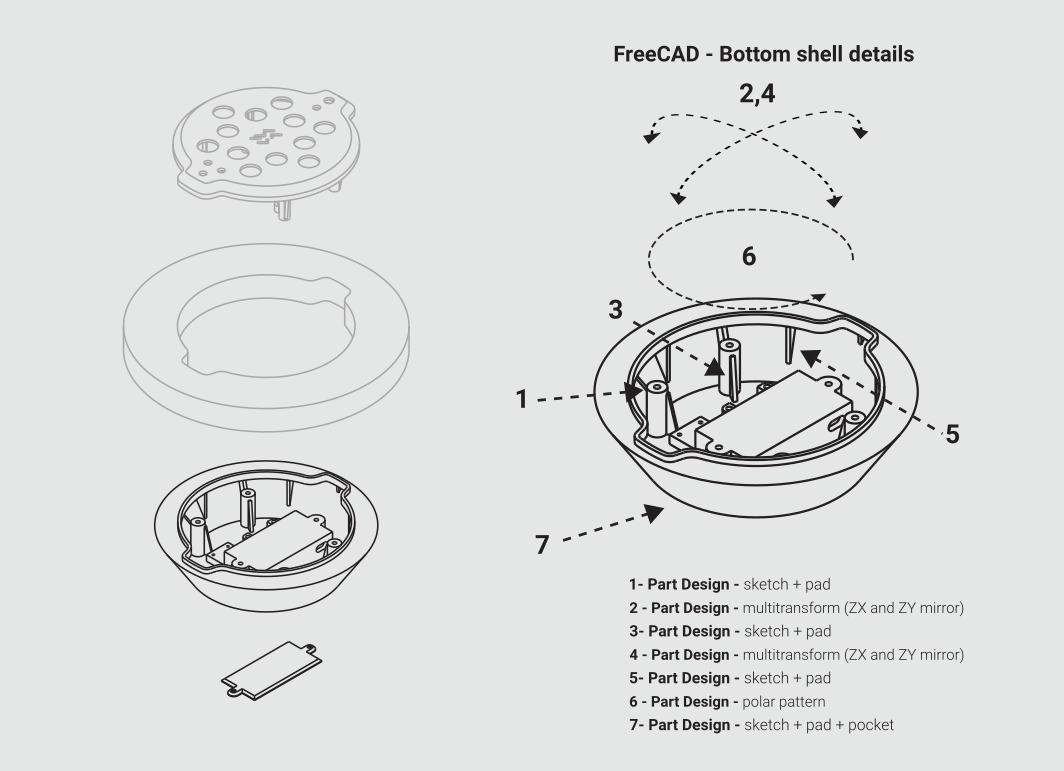
The process that lead to the bottom shell re nearly the same as the ones needed to design the top shell, the only significant difference in this procedure is that I also had to make a (long…) series of pad/pocket to make the battery slot, the support for the MIDI socket and the tag. I used similar commands to realize a cap to close the battery slot.
6 – 2D - design a mark to communicate the gyroscope position
Generally when working with CAD you start with 2D and then you move to 3D, but in this case (not counting the lot of 2d sketches that are part of the 3d model) the things went the other way around… In fact I used Inkscape to work on an element that will be placed in correspondence with the position of the gyroscope, so that the user will know that there’s something important in the center of the device, but at the same time I don’t want this sign to be too obvious. To Design such a thing in an agile and effective way I switched to Inkscape. After a few attempts I went for a quite twisted concept, which is a representation in morse code of the XY axis that the gyroscope will detect to tweak the sound. To design the pattern I used the bezier commands, but to use it in freeCAD I need to convert the thickness of the vectors I’m using into a complete shape that can be extruded. To do that I use the command “stroke to path”, and that was it.
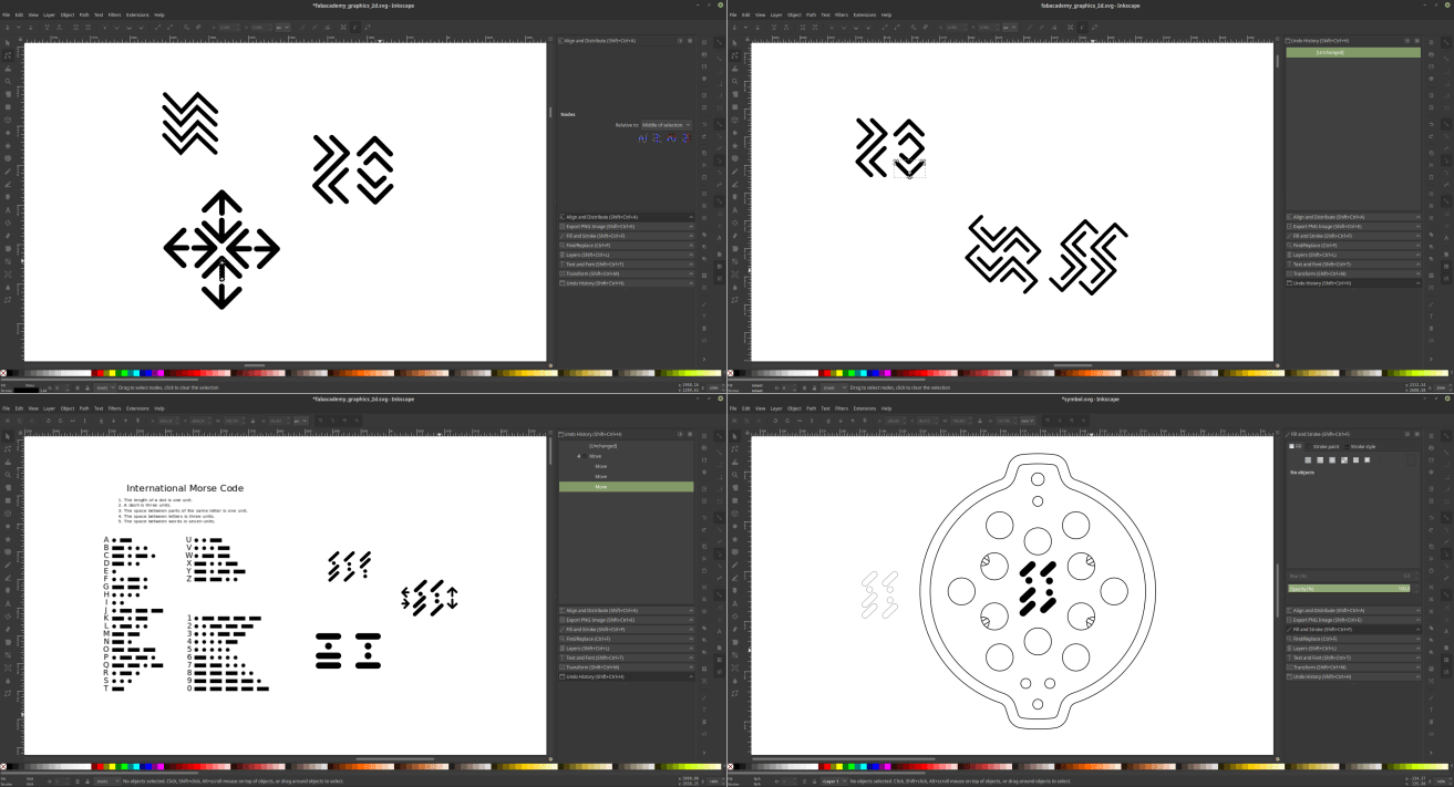
7 – 2D - import the vectors in freecad
Once the design was done all I had to do was ti import it back on freecad, turn it into a sketch through the “Draft” workbench and use it as a base for a “pocket” command in my top shell.
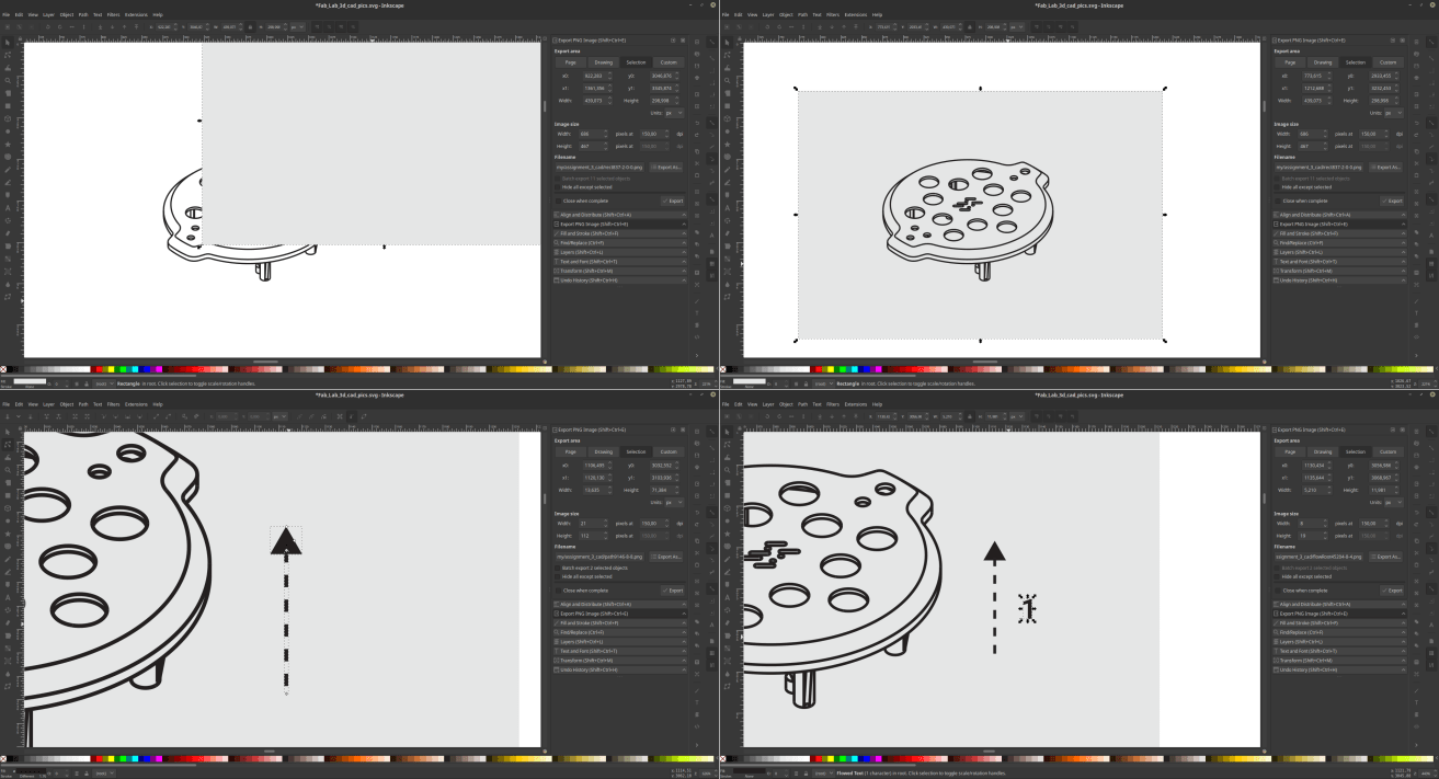
8 – 2D - documentation design
So, the documentation of an assignment it’s somehow part of the assignment itself. The more extensive use of Inkscape it’s been in fact the realization of the images for the documentation you are reading right now… To effectively document all the steps I realized some info-graphics that explain all the commands and the details of my 3d modeling session. Inkscape offers a whole lot of possibilities to do such a thing. I started by use Freecad to make an isomeric representation of my design, through the “Draw” workbench. Once the drawings are exported in SVG it is possible to just open them in Inkscape and start working on them
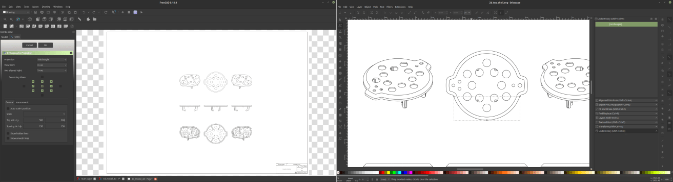
To make the info graphics I first realized a background box and stored it behind the graphics.
Then I made some arrows to show the various aspects of the project, by drawing triangles and dashed lines (tweaking the stroke style of them).
I also used some text boxes to describe with text and numbers the content of the tables.
Last but not least, I worked with the opacity of the various elements to create a clear hierarchy between the various elements of the tables.
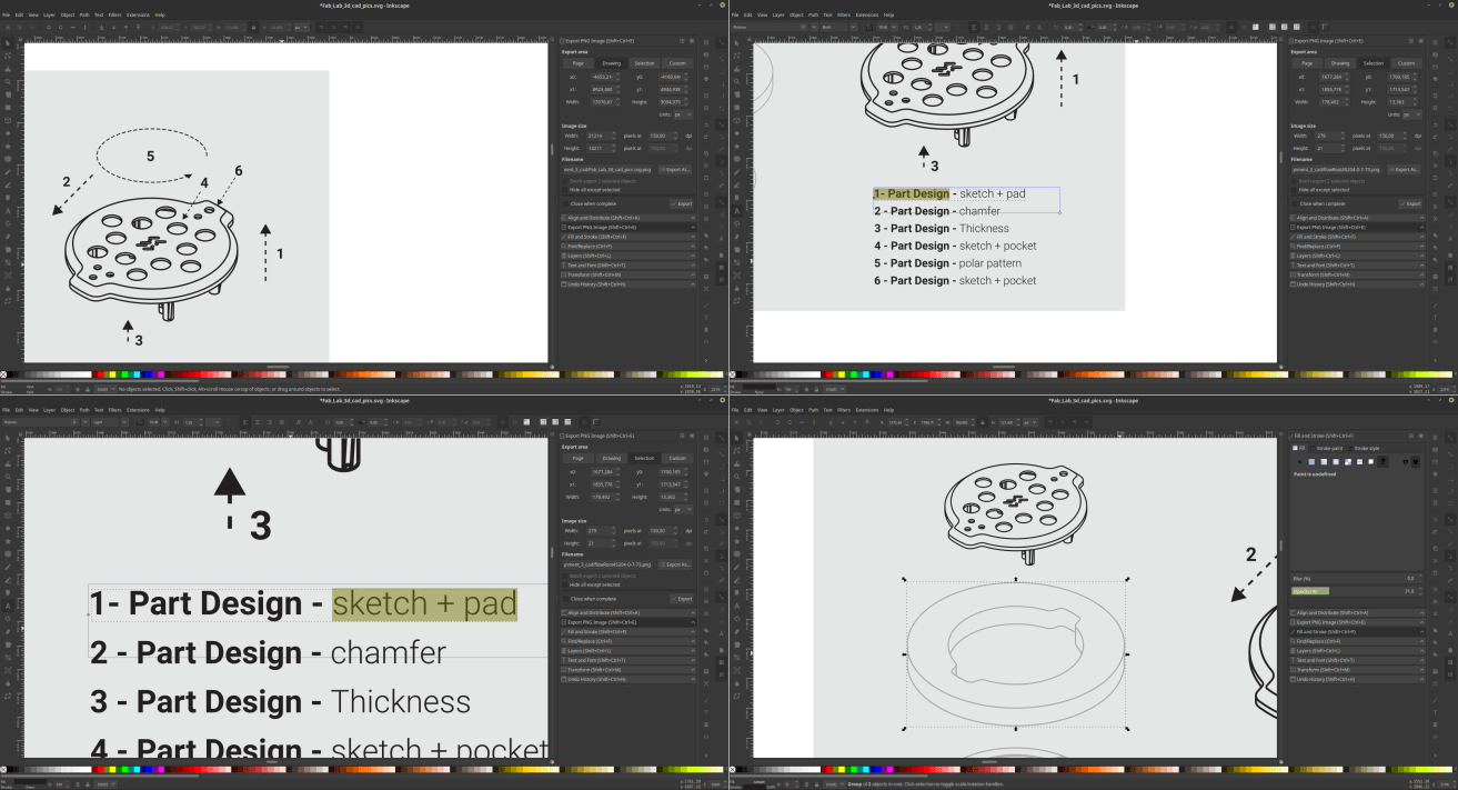 And that was kind of it, all the pictures where exported in PNG format at 150 DPI, you already saw all of them…
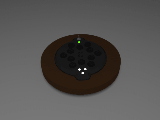
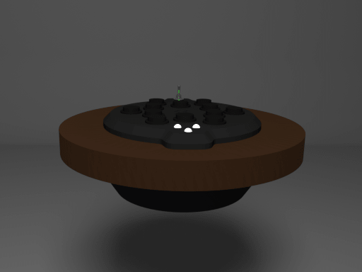
9 – Render – Blender Cycles
The very last thing I’ve done it’s to use Blender to make some photographic simulations of my object… To do that I exported STL files from FreeCAD and imported them back into Blender, which offers a very powerful set of functions to render my project.
10 – Render – setup a set
The first thing to do it’s to create a virtual set where to place your objects, this set contains a background, some lights and obviously a camera, setting the materials accordingly to the colors/lightness you want to give to your render. You can access those property on the right side menu.
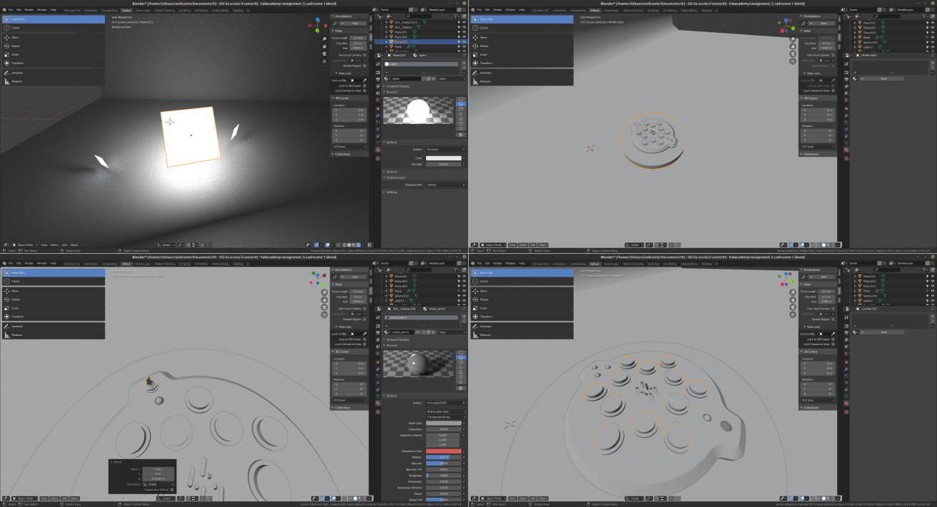 Once the set is ready it’s time to place the models into it, and find a good angolation for your camera. I also modeled buttons and added a few spheres to simulate buttons and LEDs.
To do that I navigated to the add > mesh > cylinder/sphere
Nest thing to do is to attribute materials to each part of the model. I used simple black matt materials to everything and added a wood texture to the wooden element, all this in the right side menu
Once the set is ready it’s time to place the models into it, and find a good angolation for your camera. I also modeled buttons and added a few spheres to simulate buttons and LEDs.
To do that I navigated to the add > mesh > cylinder/sphere
Nest thing to do is to attribute materials to each part of the model. I used simple black matt materials to everything and added a wood texture to the wooden element, all this in the right side menu
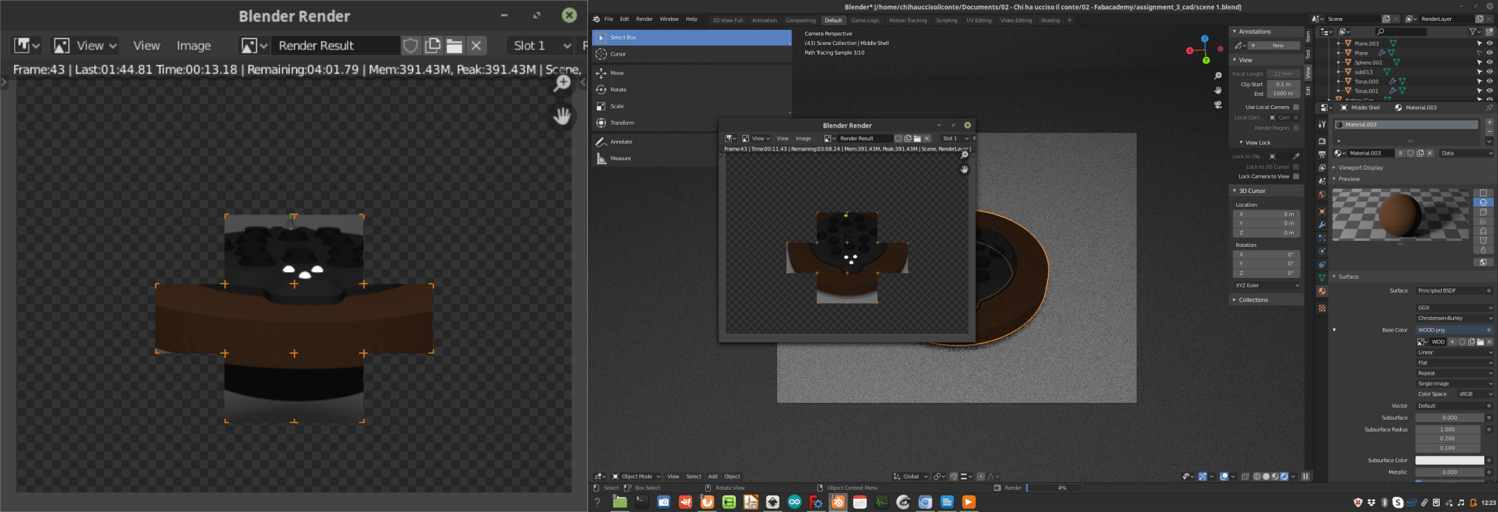
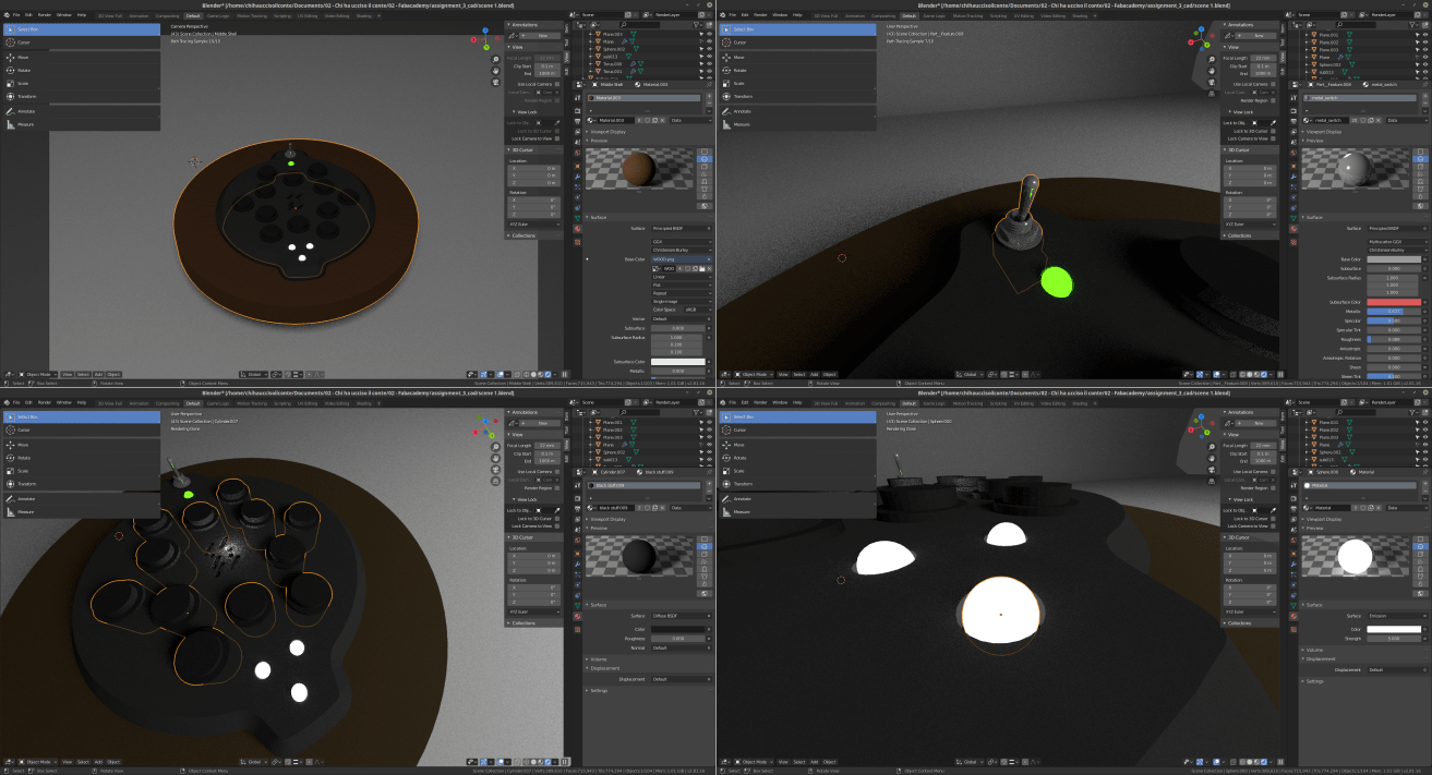 after that, once I was happy with lights, position of the pieces, materials etc… I navigated to the top menu and clicked on “Render”!
11 – source files
Here are all the source files for the Computer aided design assignment:
1 – FreeCAD 3D model
2 – Inkscape SVG
3 – Blender scene
12 – Notes, takeaways and plans for the future
I took quite an effort to make all the 3d files that are necessary to turn my sketch into a 3d model. I do have some experience in the field, but I must say that even something you are familiar with gets harder when you have to document and explain what you are doing in the process. I’ll try to improve this part of the program and fit it better within my workflow. From a technical point of view I would like to explore a little deeper some 3d animation that I could not make so far.