Assignment #14
networking and communications
The 14th assignment of the Fab Academy consists in design, build, and connect wired or wireless node(s) with network or bus addresses.
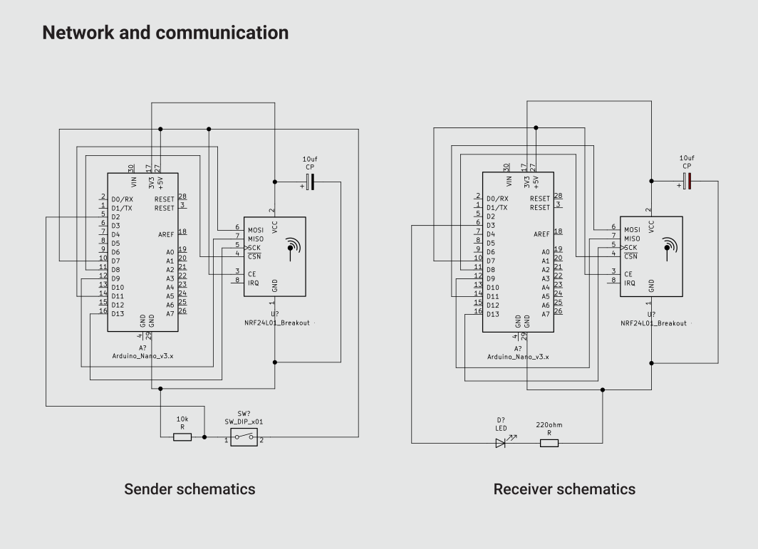
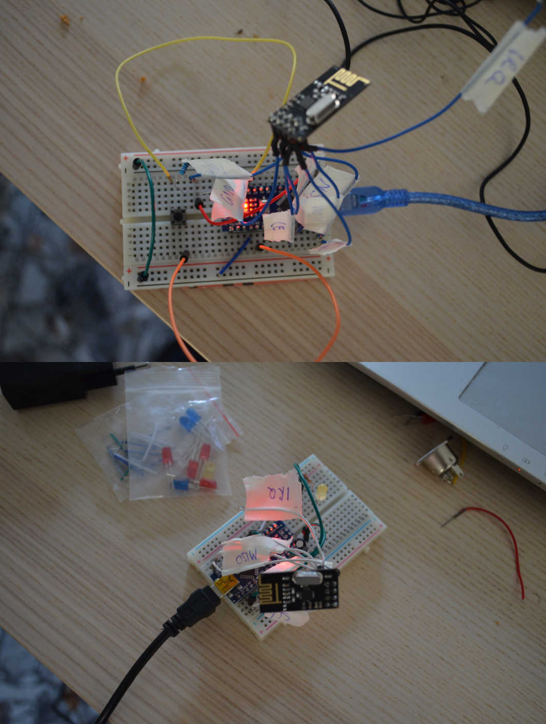
1 – schematics
Because of the “usual” pandemic emergency I cannot access the lab, and therefore I used two Arduino Nano boards and two NRF24L01 modules to make a network where one node has an input device (a button), and the other has an output device (a yellow LED). So, I took two breadboards, soldered wires to the modules and connected the various components. The most interesting aspect of this phase was the utilization of a 10uf capacitor to stabilize the power that feeds the radio module.
2 – Code
The code is quite straight forward. I used the commands of the RF24 library to define a radio channel, open a communication between the two device, and then send the button state to the receiver so that he can use this data to turn on and off the LED. In order to make my network function I need to upload both the controller with a program:
transmitter code
receiver code
The network is very simple, but it works, and I can see that there’s a lot of potential to explore in the future. to know more about this technology I invite everyone to check this very nice tutorial that I consulted to make my assignment
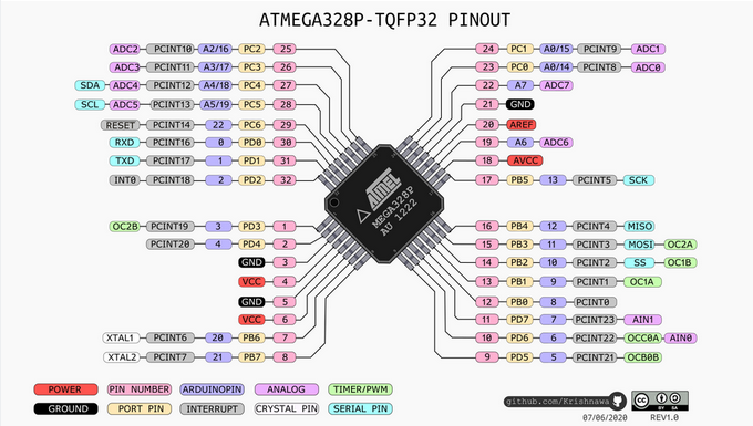
3 – Receiver Board Design
Once again, to mill PCBS during a global pandemic it's not really possible, however I'm going to design PCBS to complete my assignment.
The first PCB it's going to be the receiver, that I will make using an ATmega328P, so I'm going to check the pinout to see how to connect my components (although by now I know this controlle very well!)
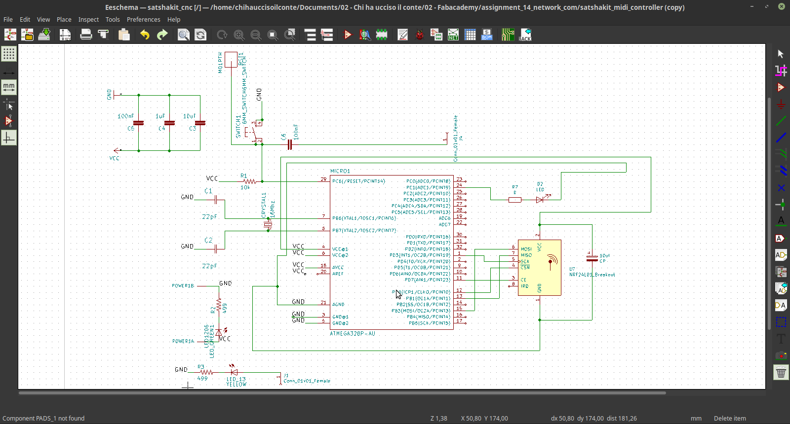
 Then I used KiCAD to design the schematics:
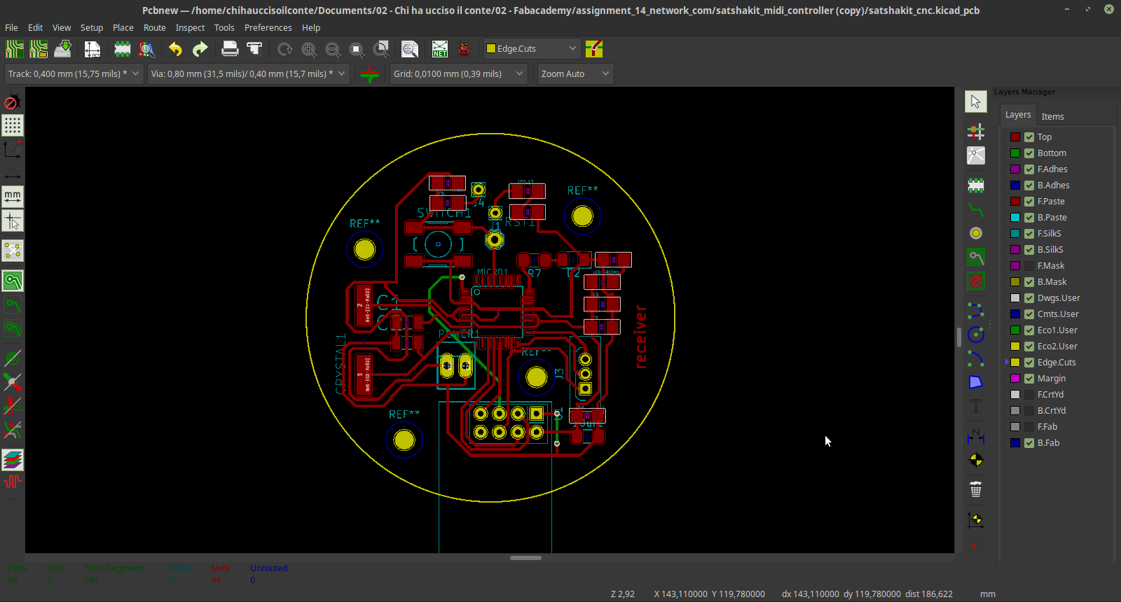
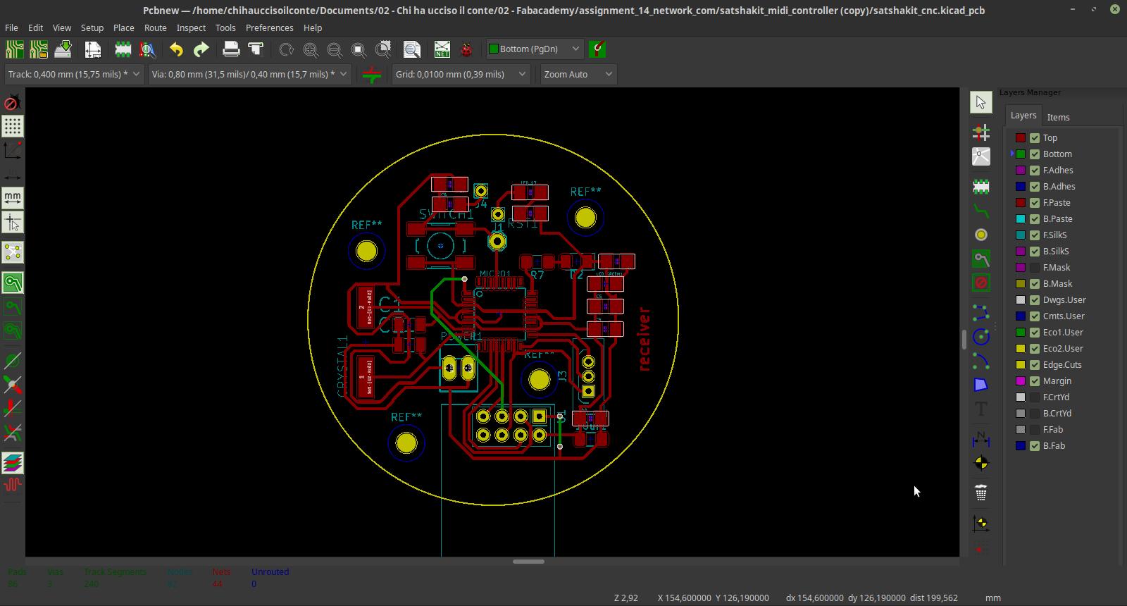
 Then I switched to the PCB design features, and routed everything.
To explore a little bit the possibilities of the software I decided to make a circular PCB, and I added a text. Since the circuit is quite complex I used a double sided layout.
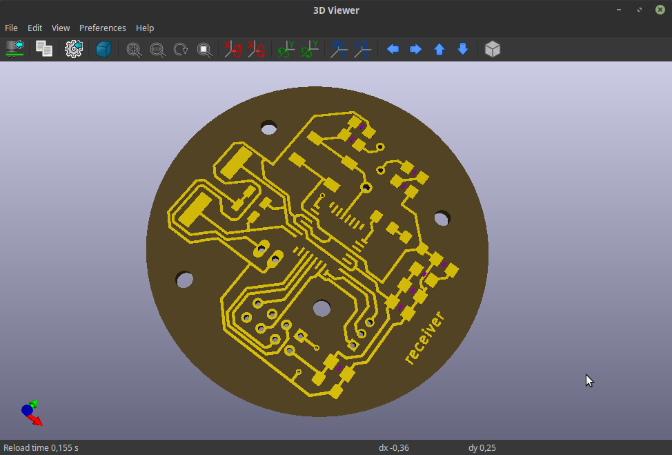
 here is the final result visualized through KiCAD 3D viewer:
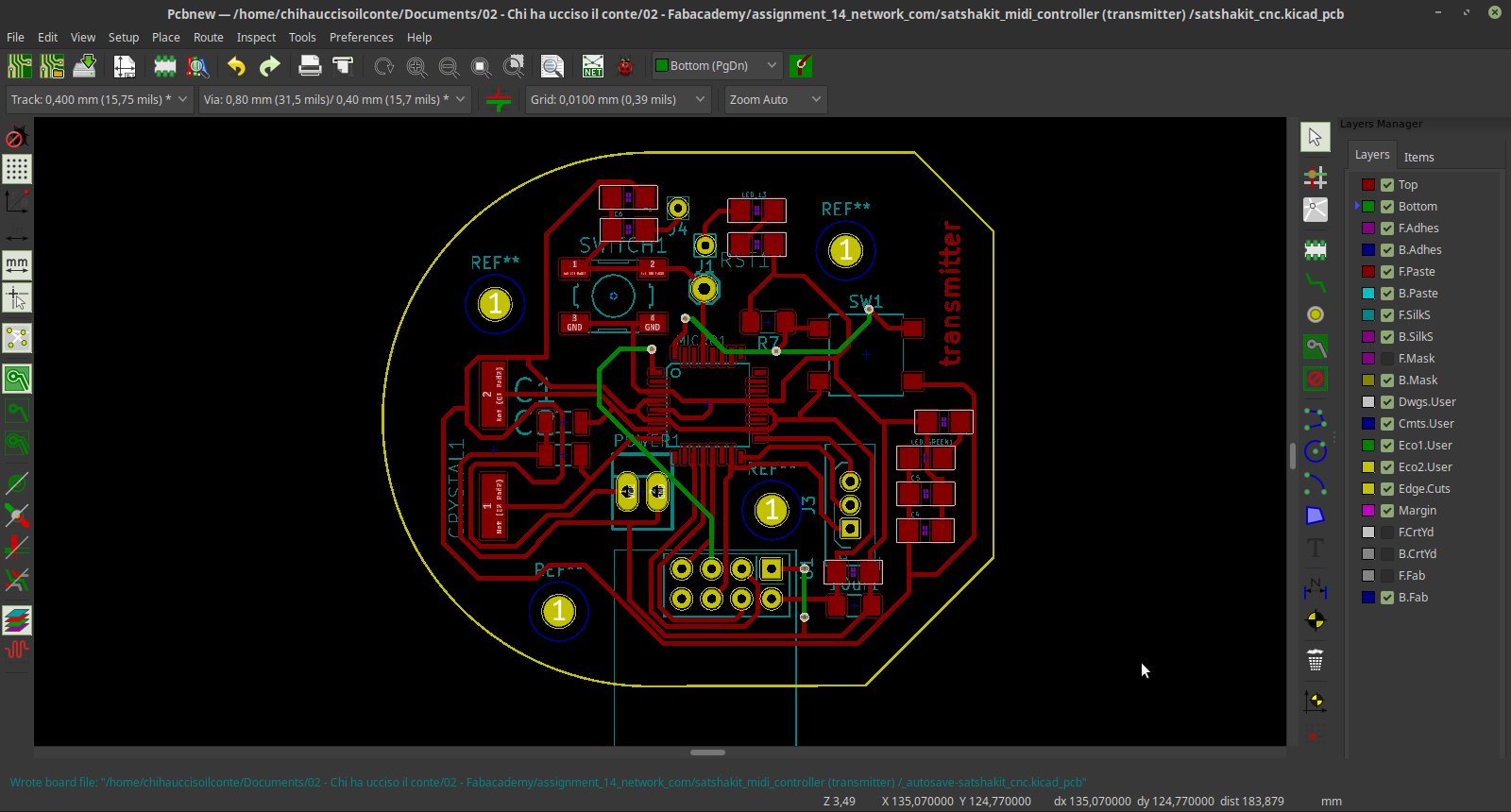
4 – Transmitter Board Design
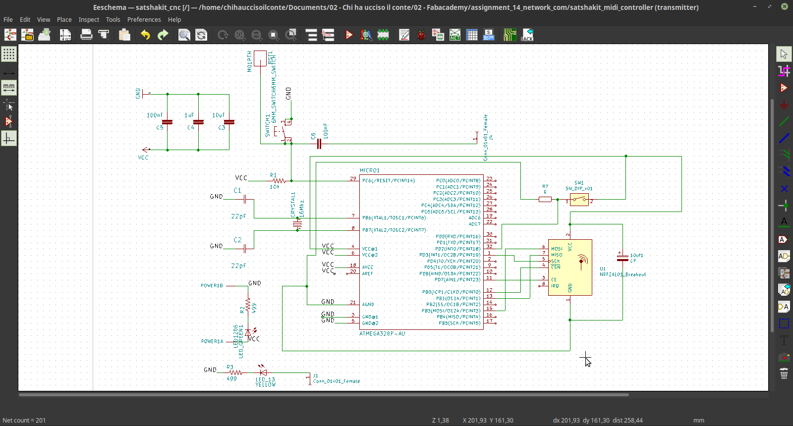
The same principle where applied to the design of the transmitter board
I used KiCAD to design the schematics:
 Then I switched to the PCB design features, and routed everything.
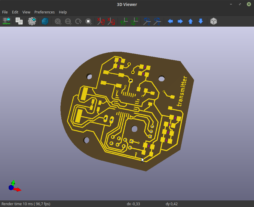
This time the board it's not circular, I went for a polygon shape, and added a text again.

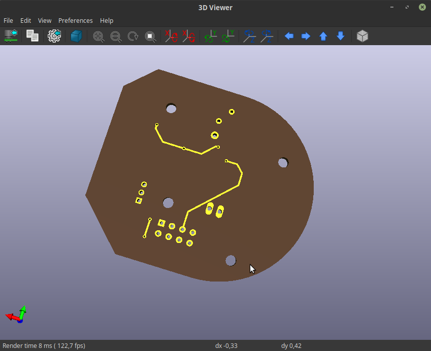
 here is the final result visualized through KiCAD 3D viewer:
source files
Here are all the source files for the Network and communication week:
1 - transmitter code
2 - receiver code
2 - receiver PCB
2 - transmitter PCB