Assigment #12
Interface and application programming
The 12th assignment is about Interface and applications programming, and we have to code an interface that would work with a circuit made by us. To fulfill this task I’ll design a very basic musical instrument to be controlled with (a portion of) the circuit I designed for my final project
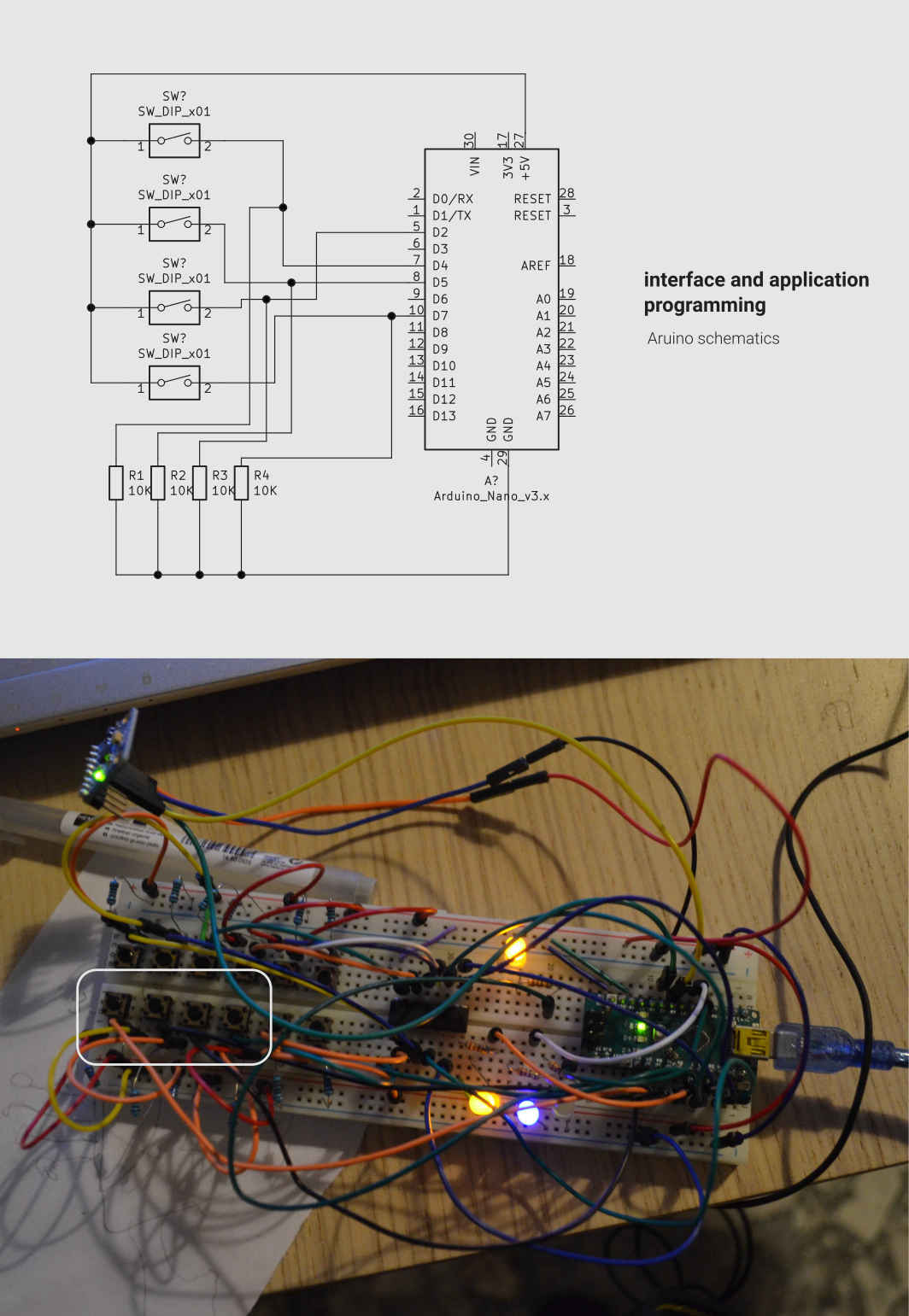
1 – circuit
The first thing to do it’s to put together a circuit, as previously mentioned, I’m going to use a part of what I’ve dome previously as an input device to control the instrument I’m going to code. Due to the pandemic that is currently hitting hard on our planet, my circuit it’s made out of an Arduino nano, connected with 4 buttons that I’ll use as an input
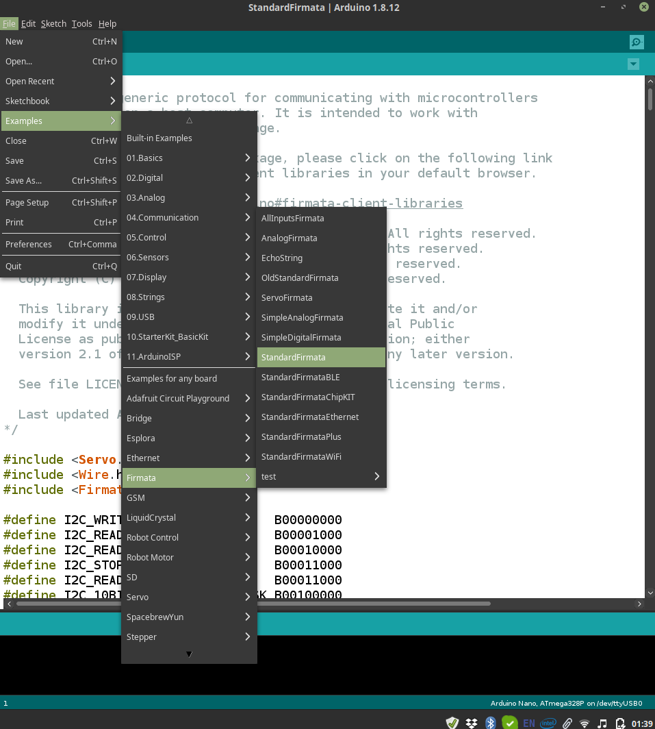
2 – uploading Firmata code to the Arduino
In order to establish a contact between the Arduino and my computer ap I’ll have to upload a sketch that will establish a connection between the Arduino and my computer. To do that I just have to open the Arduino IDE and navigate to File > Example > Firmata > StandardFrmata sketch. Click upload and wait a few seconds, until the upload it’s done
3 – Processing
To code my interface I decided to use Processing, a coding platform very similar to Java that allows the user to code very nice programs. My code is based on the use of the Minim library that manages the sounds and the Arduino library that will take care of the signal coming from the circuit. Inspired by one of the examples of the Minim library I decided to design an interface that will have a a layout with 2 lines that will visualize the frequency of the sound emitted and, right below that , four buttons that will “turn on” when the buttons on my board are pressed, this will provide a visual feedback for a hypothetical user.
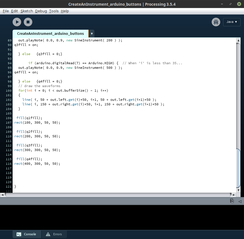 Here Is the Processing code:
I like very much the result of this coding session, the interface I coded works well and I think it’s very elegant. I’ll definitely explore further the capabilities of Processing and the minim library to combine nice visuals and interesting sounds.
Here are some videos of the interface running:
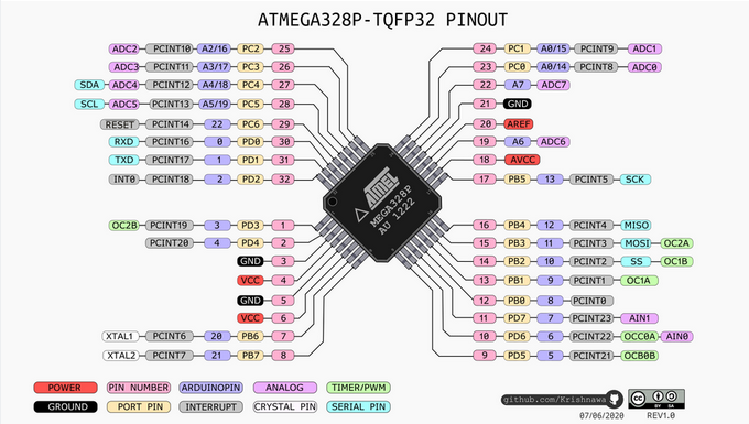
5 – PCB Design
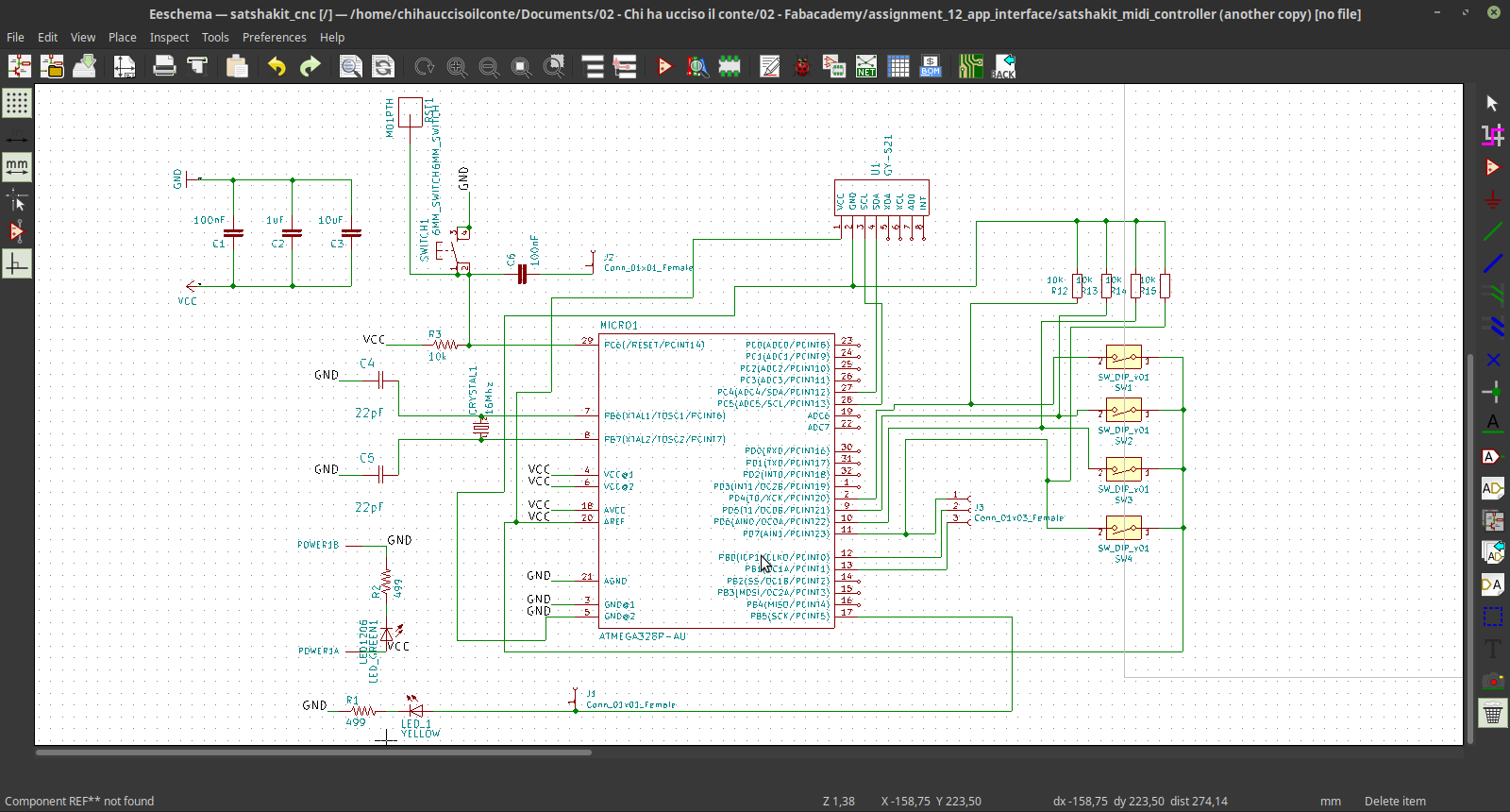
To complete the assignment I designed a PCB that can work as an interface for the app I did during this session. Due to CoVid it's impossible to mill the board, but I'll still design it for the future. The board will be based on an ATmega328P, and will include the buttons that are necessary to command the processign sketch. To design the board I used again KiCAD. The first step was as usual to check the pinout of the controller and the design of the schematic.
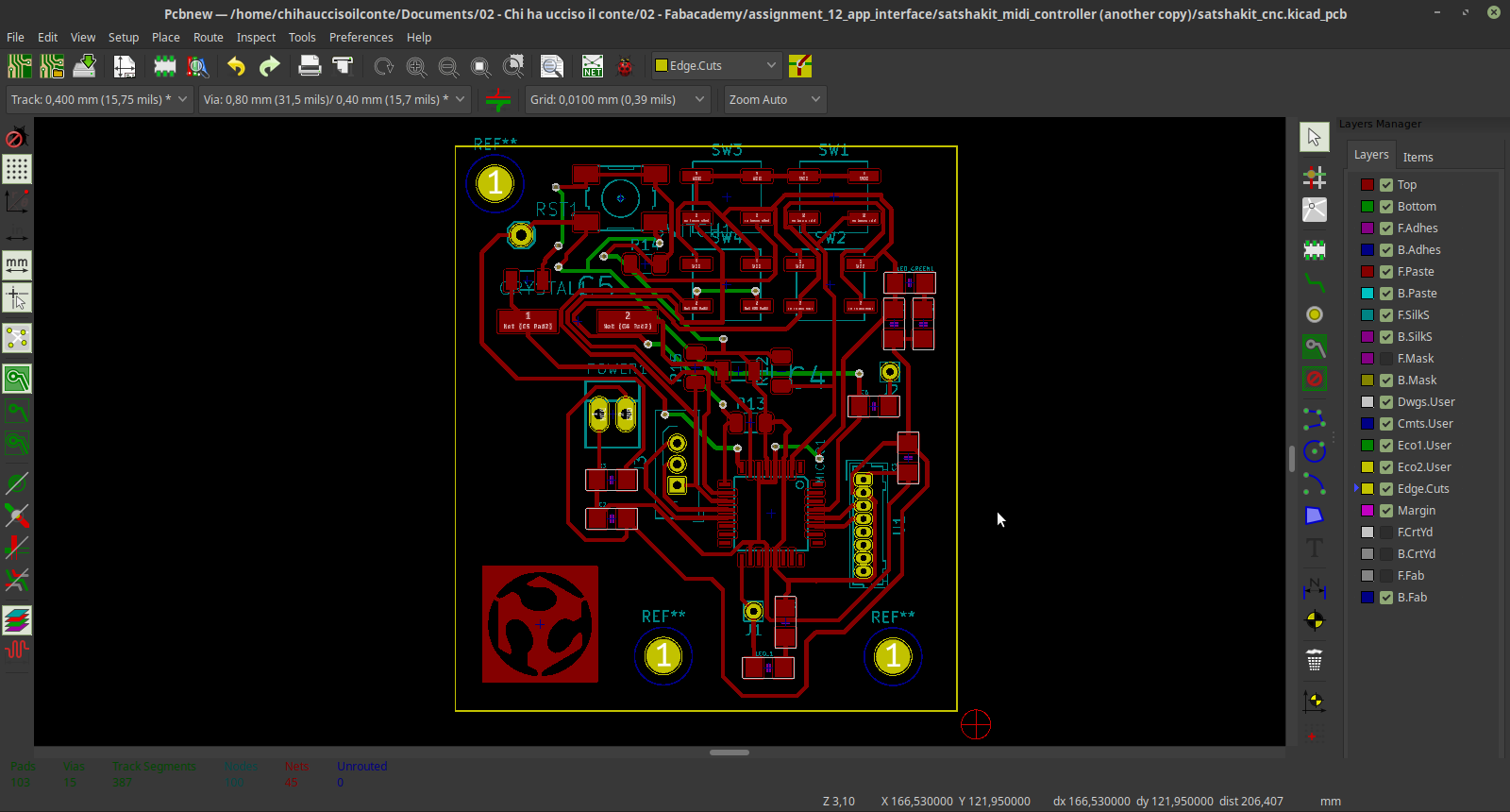
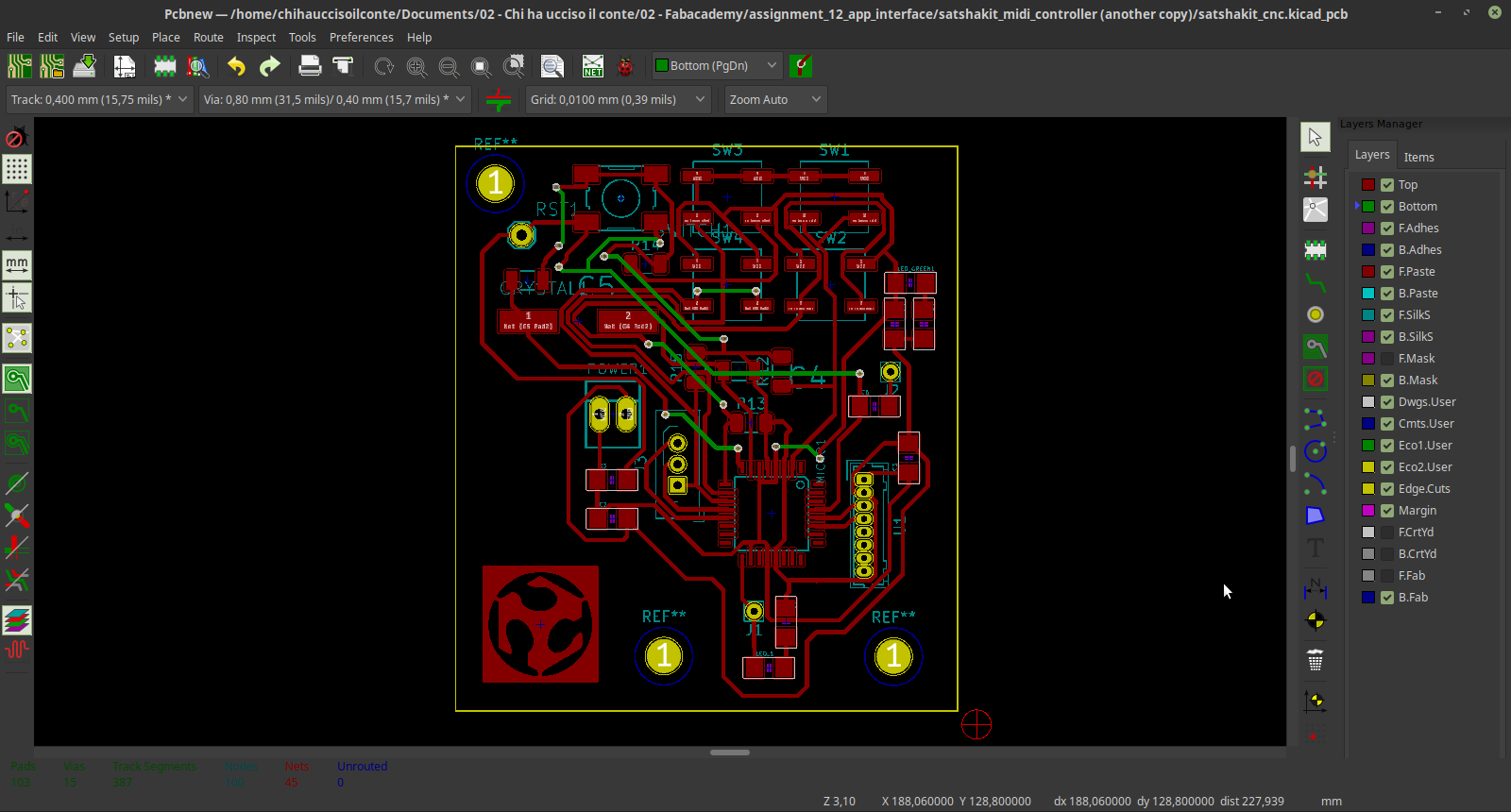
Then I moved to the PCB designed and connected all the footprints. since the pcb was a little conplex I made a 2 layers board.
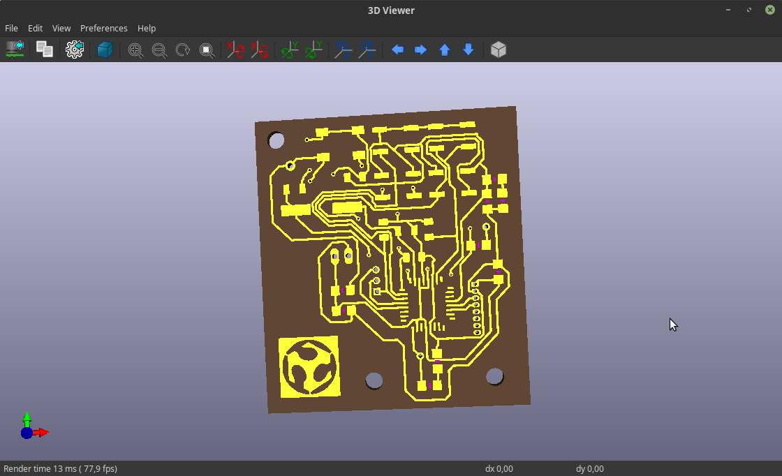
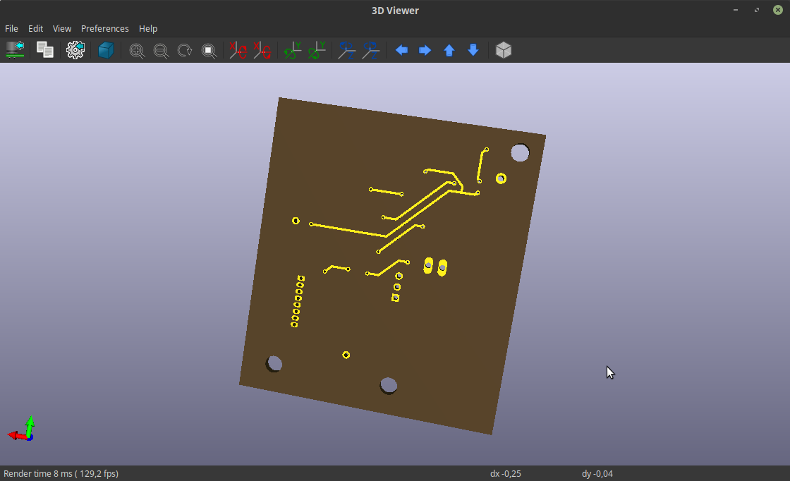
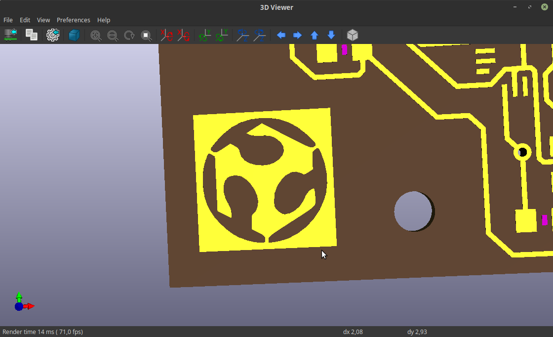
And used the 3d viewer to see how the board will look.
/p>
6 – Symbol design
You may have noticed that on the board there's the simbol of our beloved cult.
That's because I decided to create a symbol to include in my board to make it more personal.
To do this I watched this tutorial.
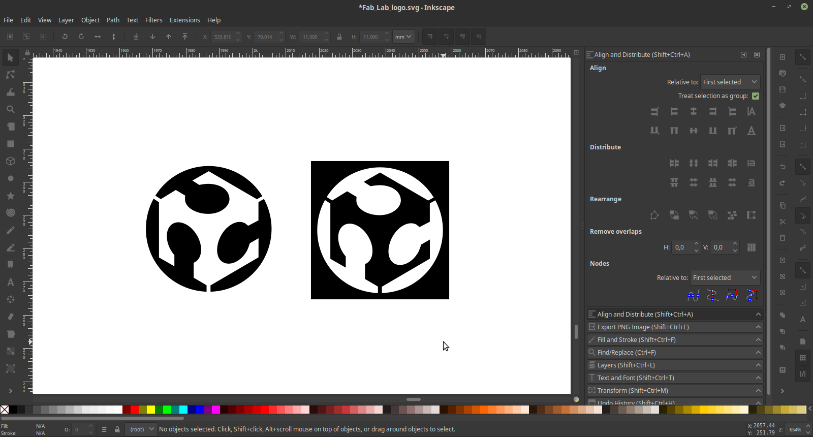
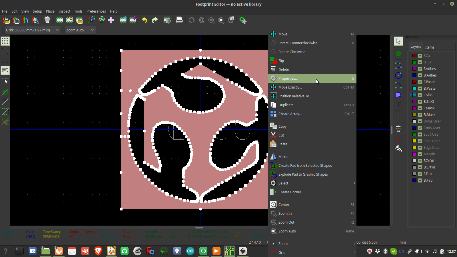
I first used Inkscape to draw the graphics I wanted to include (in black and white), and exported in in PNG format
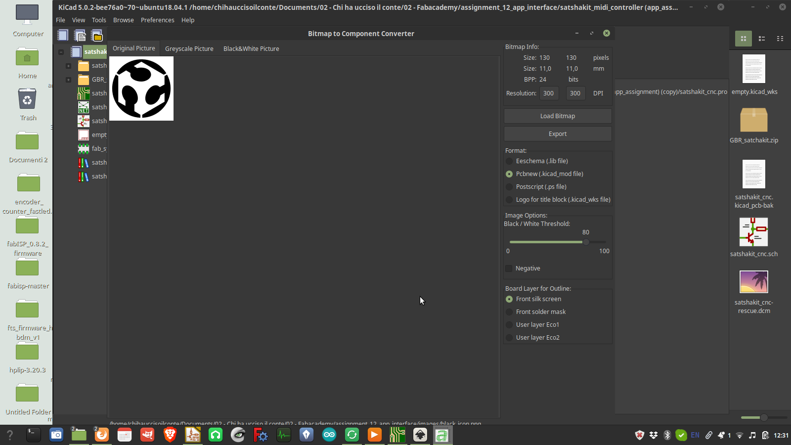
 Then I opened kiCAD and went to the "Import bitmap" section. Here is possible to import the image, tweak the contrast, and export it as a symbol. Note that only the white parts will appear in the PCB (although it's possible to revert the colors).
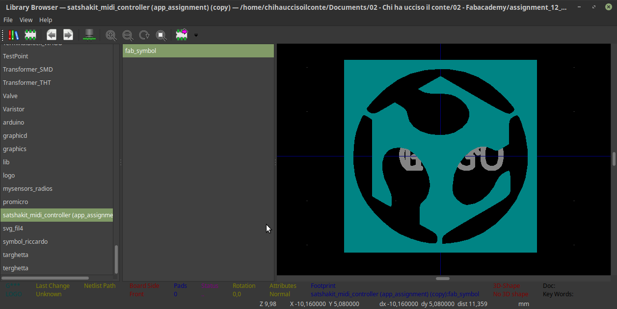
After this I moved back to the PCB design, and navigsted to the footprints manager to include the symbol I did in my library.
Last thing was to add it to the design, and here it is.
Then I opened kiCAD and went to the "Import bitmap" section. Here is possible to import the image, tweak the contrast, and export it as a symbol. Note that only the white parts will appear in the PCB (although it's possible to revert the colors).
After this I moved back to the PCB design, and navigsted to the footprints manager to include the symbol I did in my library.
Last thing was to add it to the design, and here it is.
 One last thing that I did was to move it to the top traces layer, so that it can be milled together with the traces.
source files
Here are all the source files for the Interface and application programming assignment:
1 - 4 buttons sound interface processing file
1 - 4 PCB Files