界面与应用编程
小组作业
- 尽可能多地比较各种工具选项。
个人作业
- 编写一个应用程序,让用户与你制作的输入和/或输出设备进行交互
学习成果:
- 解读并实现设计与编程协议,以创建图形用户界面(GUI)。
你是否
- 链接到小组作业页面
- 记录了你的过程
- 概述了遇到的问题以及如何解决
- 包含原始代码(如果无法提供,则附上应用代码的截图)
- 包含你的应用配合你的电路板运行的“主视觉图/视频”(hero shot/video)
使用的软件
- 对于 VS Code,请按照这个 链接,看看我如何搭建一个基础项目。
- PlatformIO
- Brackets
- Arduino IDE
- MIT App Inventor 2
小组作业
其他小组作业请前往 小组作业页面。
这项作业完全由我完成,因为今年我是 Algarve FabFarm 唯一的学生。
应用
MIT App Inventor
MIT App Inventor 是一个出色、简单、免费的工具,可以设计手机应用。它有两个版本:一个需要安装,另一个是最新的版本,完全在线。
文件
步骤:
- 要访问在线版本,请前往这个 链接。
- 接下来,用你的 Google 账号登录。
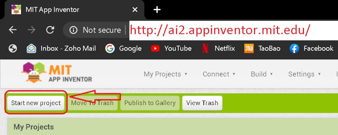
- 点击“Start new project”。
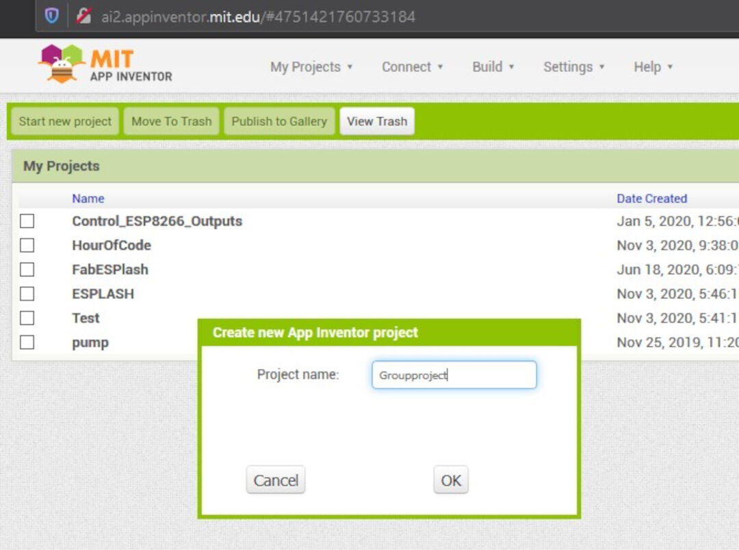
- 给项目起个名字。我的叫“groupproject”。
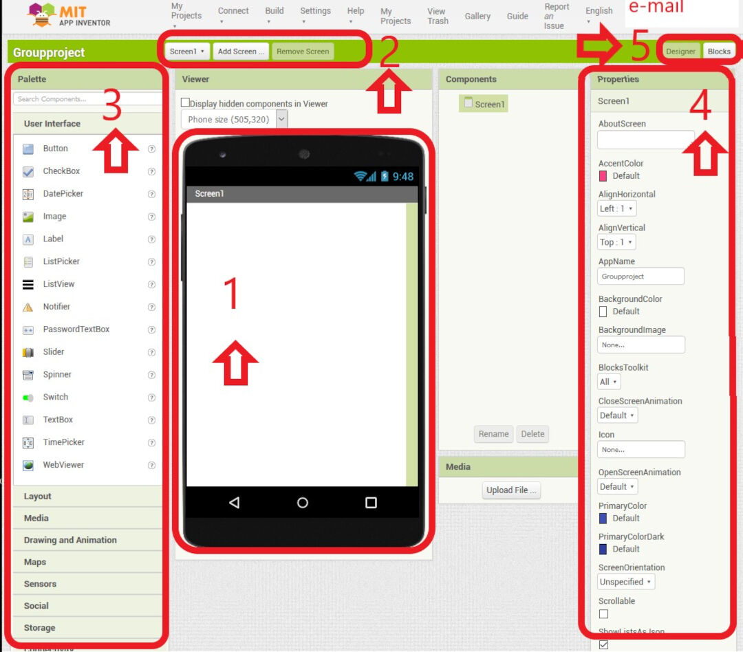
- 中间的 #1 是保留给应用设计的区域;#2 在你想要多个屏幕时会用到;#3 在左侧,是组件面板,包含按钮或视频播放器等所有用于可视化搭建应用的对象;在 #4,也就是右侧区域,可以编辑每个对象的属性;#5 切换到块编辑区,应用的逻辑就在这里创建。
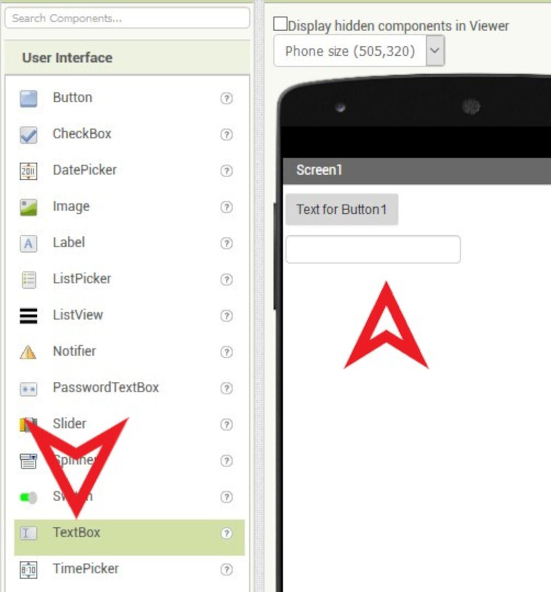
- 在这个快速示例中,我把一个按钮从左侧拖到屏幕上。
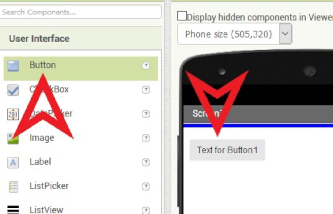
- 这里我也演示了如何像按钮那样添加文本,不过我的应用里不会用到这个文本。
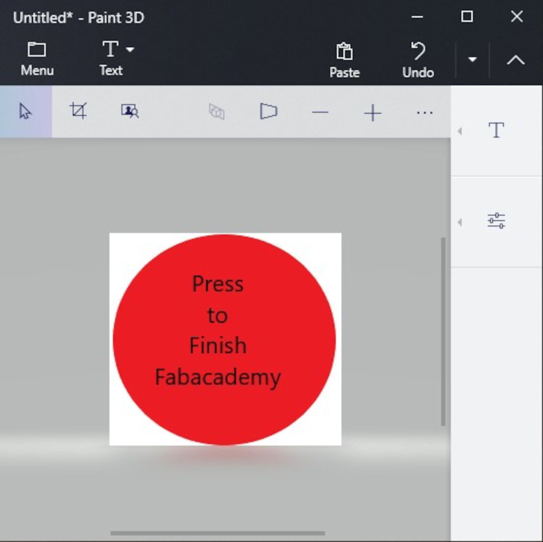
- 我用 Windows 10 的 Paint 3D 应用,很快画了一个大红色按钮。
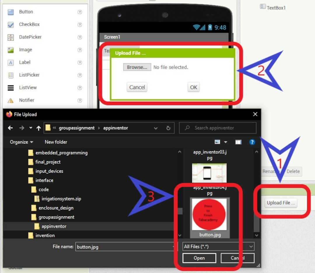
- 接下来,我把红色按钮上传到 MIT App Inventor。每次使用媒体元素时都会走这个流程。
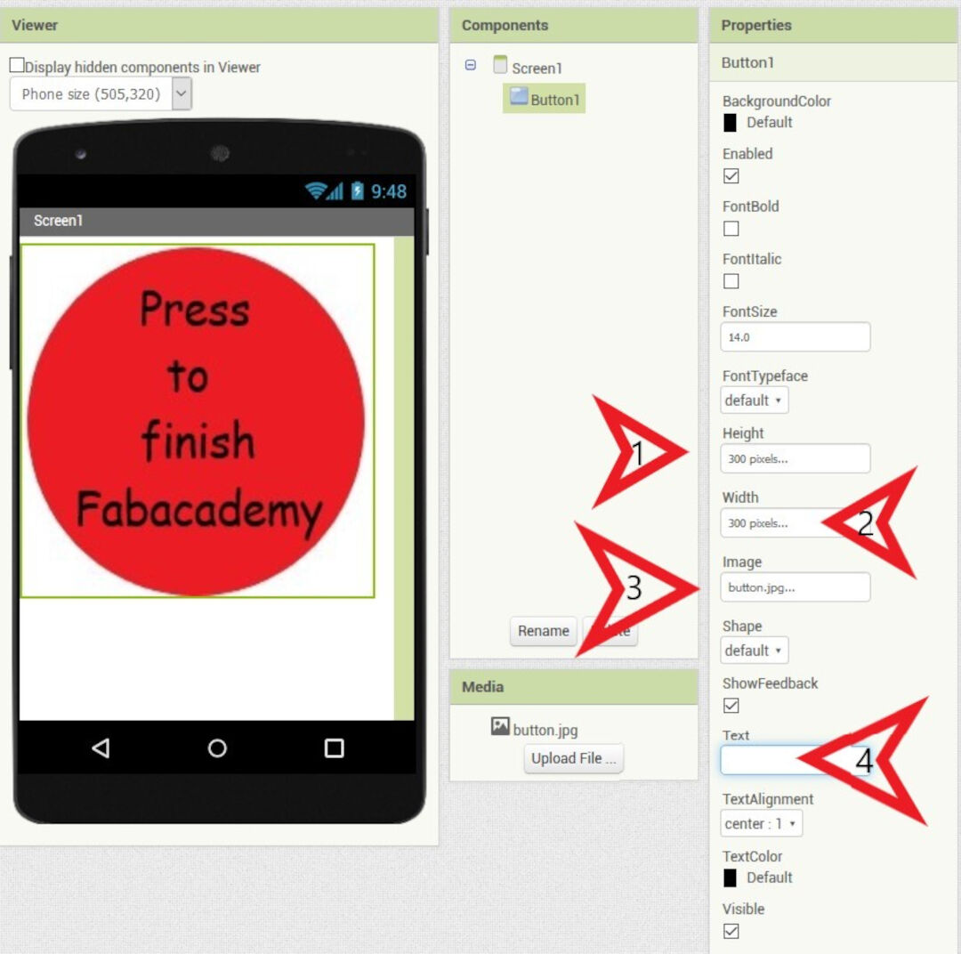
- 然后我编辑它的属性,比如高度、宽度和文本。在 #3 中我指定用作按钮的图片,在我的例子里就是那个大红色按钮。
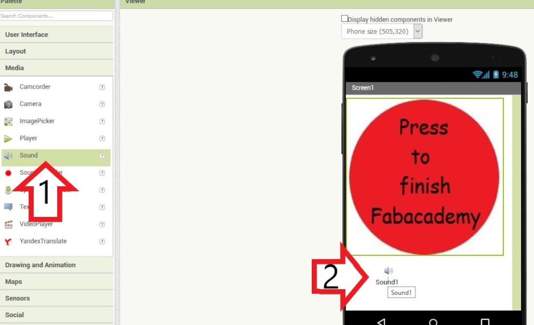
- 然后我把一个声音对象拖到屏幕区域。把这个对象关联到媒体的流程和之前一样。我也会对视频重复一遍。
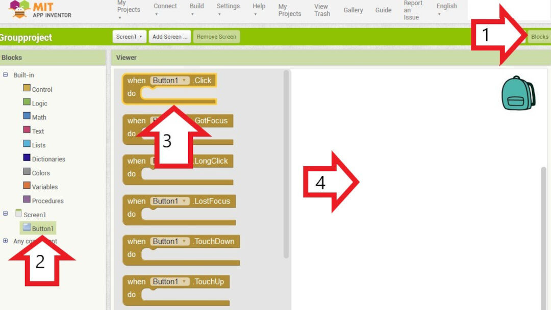
- 接下来,我切换到右上角的块编辑器区域。点击按钮会打开可以添加到应用逻辑中的块。然后我添加一个按钮点击块。
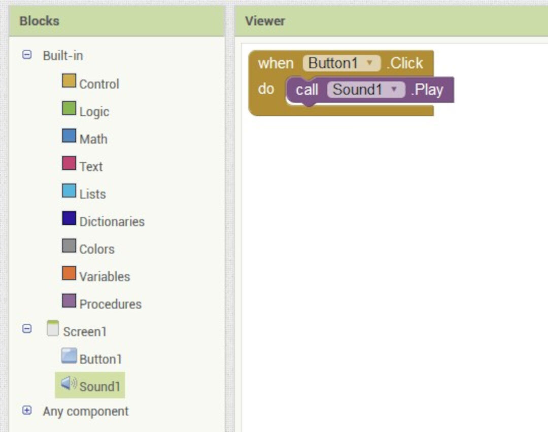
- 点击声音块并从选项中选“call sound1.play”,我就能给按钮添加一条在它被点击时执行的命令。
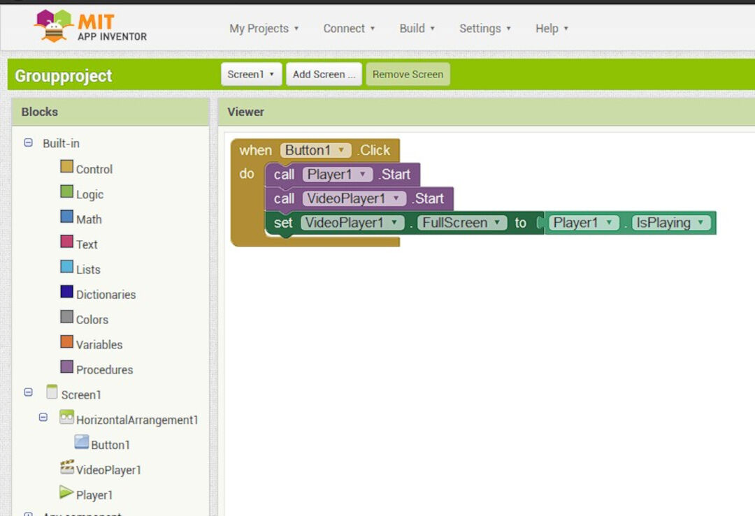
- 我像之前一样操作,添加一个视频,然后让它全屏打开。
- 应用完成后,我生成一个 APK,并保存到手机的文件系统里,以便安装程序。
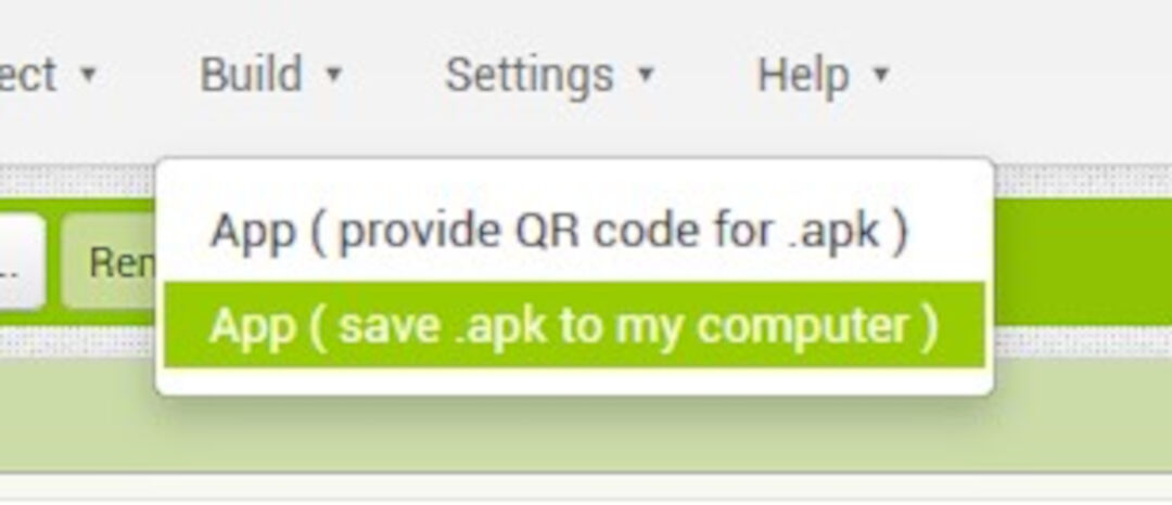
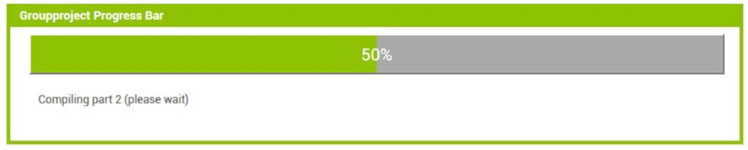
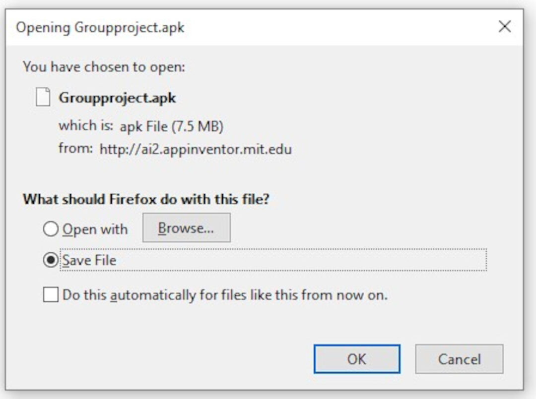
- 在手机上,我找到保存 APK 的位置并安装。Play Protect 会尝试阻止这个应用,但可以忽略。
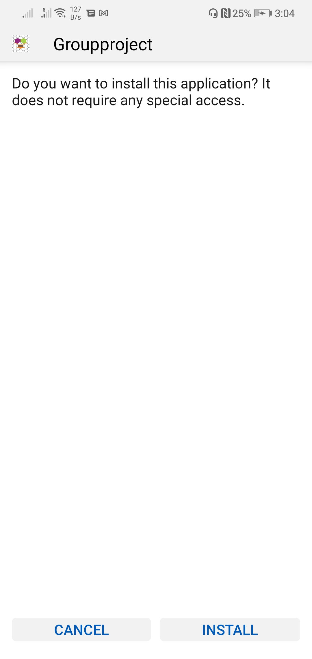
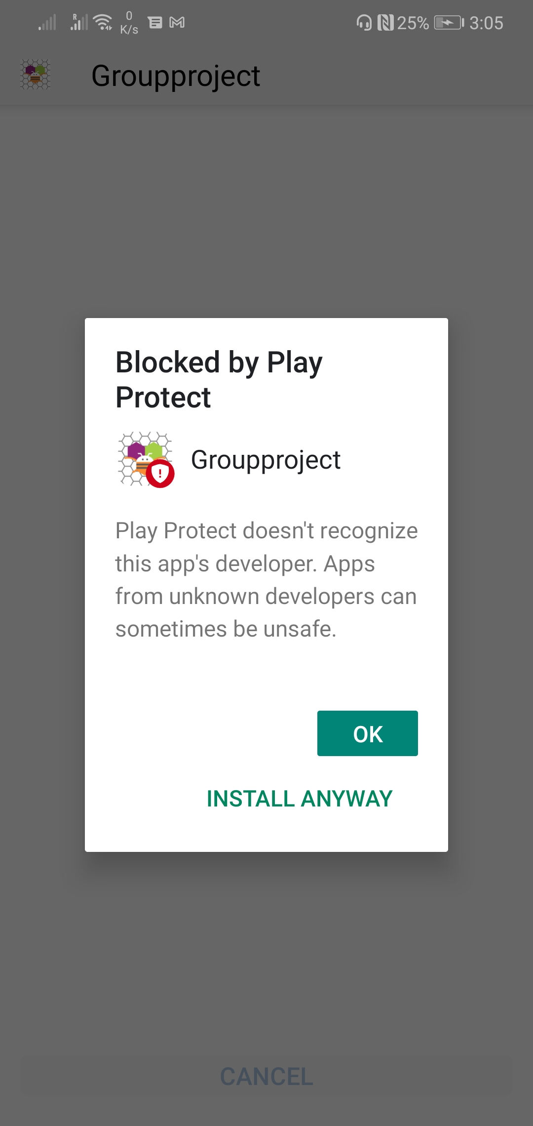
- 这就是小组作业中做出来的应用。
文件
简介
这项作业是我 最终项目开发的一部分。
因为我的最终项目改成了灌溉系统,所以我开始开发它的网页界面。
要把各项能力分开、只在这里留下我项目中与界面有关的部分,真的很难,所以有些地方会涉及其他周的主题。
到目前为止的设计就是上面这个。我还需要为最终项目修改它,因为我不想让它只是启停水泵,我还想要按区域排程等功能。
下面我会整理走到这一步的步骤,其中一部分与我的 项目更新2重叠。
在我写这段文字的时候,还没有当前的设计文件,只有一份代码草稿,还有一个面包板上的原型!
另一方面,硬件和软件都有需求:
软件需求与阶段
- 通过创建更多函数来简化代码;
- 尝试把 HTML 部分分离出来,让代码更干净;
- 改进代码的外观/界面;
- 向 HTML 添加读数;
- 添加事件日志,比如过流;
- 为设备增加更多安全保护;
- 添加手机界面(APP);
- 添加设置当前时间的功能;
- 为每个继电器添加重命名功能,这样可以把它关联到关注的区域,或者至少把继电器改成农场实际区域的名称。
开发
2020年6月7日
到今天,2020年6月7日,开发进度是这样的。
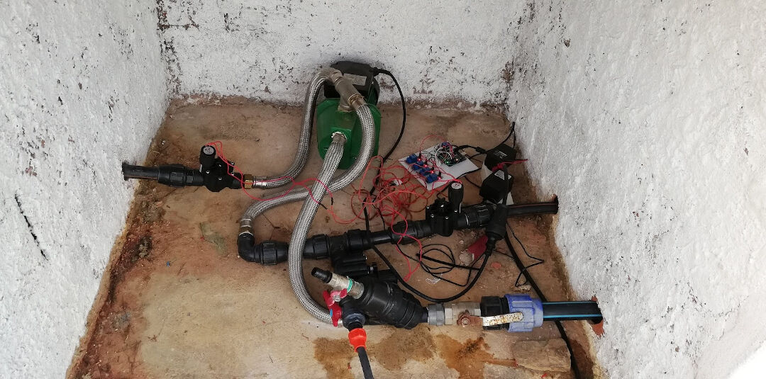
这套装置上运行的代码可以在 Fabfarm 的 GitHub 上找到: Autovalve。
我们的一位志愿者 Shakeel 成功做出了一个能在 ESP8266 上运行的版本,可以在同一个仓库的 这里找到。由于疫情,他匆匆离开了我们,没来得及测试自己的代码,所以代码虽然能跑但不稳定:他英勇地尝试让模拟引脚与 WiFi 共用,导致 WiFi 掉线,系统几乎无法使用。我就是从这份代码开始的。
2020年6月8日
在花了很多小时理解代码之后,我成功把 Shakeel 的代码移植到 ESP32 上,并且把文件拆开,让每个函数放在单独的文件里。
在这个视频里,我展示到目前为止在合并代码并让它在 ESP32 上运行方面取得的进展。
把代码移植到 ESP32 对程序员来说也许很简单,但花了我很多小时。
步骤:
- 把所有已经是函数的部分分到各自的文件里,让代码更易读;
- 然后打开另一个 Arduino IDE 会话,开始把代码的每一部分逐行复制到新会话中;在这个会话里,我把主文件重命名为“esp32irrigation”;
- 把引脚重新映射到 ESP32 的引脚;
- 在 Brackets 里对 HTML 运行 Beautify;
- 整理代码,让引脚定义放在顶部;
- 为 RTC 引脚创建变量;
- 注释掉向串口监视器打印错误的部分。
代码太大,没法在 HTML 里展示,所以我留下一个链接,指向今天清晨时的代码状态: 代码在这里。
在这个视频里,你可以看到农场当前灌溉系统的测试装置。
2020年6月9日
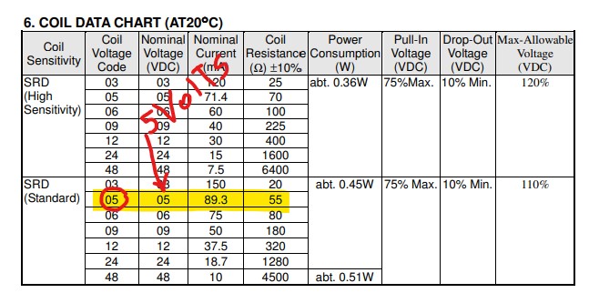
今天,在测试继电器之后,我发现有些继电器能用,有些不能用。直接在实验室电源上测试、给信号引脚加 5 伏之后,我认为这是因为 ESP32 提供的电压太低,或者是信号电压的问题。
然后我看了 Great Scott 在 YouTube 上关于 继电器和光耦的视频。
我会确保继电器至少有 5 伏电源,这是 数据手册要求的工作电压。信号用 3.3 V 应该没问题。会在现场测试。
另一个问题是电流读数,完全不对。为了让灌溉系统能工作,我会先在不测电流的情况下运行它,直到调试好。
2020年6月10日
测试之后,关于电压问题的结论是:ESP32 不应该给继电器供电;那应该由外部电源提供,设为 5 伏。信号可以原样从 ESP32 出来,但 ESP32 必须共用同一个地。
代码里的更多改动:
- 把显示时间的间隔从 3000 ms 增加到 5000 ms(5 s),改的是变量
RTCtimeInterval; - 把显示设置的间隔从 10000 ms 增加到 30000 ms(30 s),改的是变量
configTimeInterval; - 在继电器的 HTML 界面里设置了容易识别的名称;
- 进一步清理了串口监视器,从设置显示中去掉了秒。
今天早上我会把装置重新投入使用,为每次灌溉设定时间,并对 ESP32 灌溉模块做现场测试。
奇怪的是,外部 RTC 时钟走时不准。我会研究在断电时用外部电池配合内部时钟。
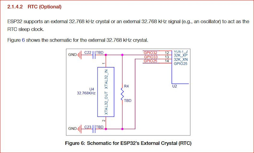
根据 ESP 的 GitHub 仓库里这个已关闭的 issue 讨论,以及这个 ESP 精度话题,内部时钟会有漂移:“Internal RTC clock frequency error is about 5%”。这可以通过按下面原理图组装一个外部 32.768 kHz 晶振来解决:
另一个解决方案是让 ESP 始终连接互联网,从互联网获取时间更新,以补偿不准确。
醒来后的更新:
今天我去安装了临时的测试装置。我排查了几个问题。
- 断开电脑时装置不工作。解决办法:电源接线不对;我最后接了两根 USB 线,一根给 ESP32,另一根给继电器,两者共用同一个地。我可能也用同样的办法解决了 RTC 时钟问题。
原型现在看起来是这样:
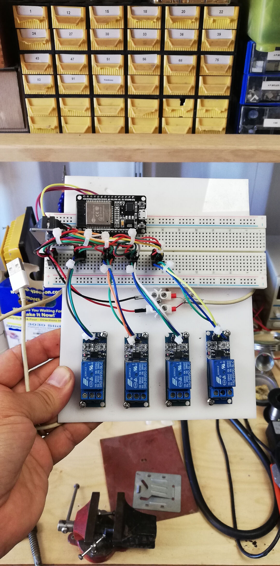
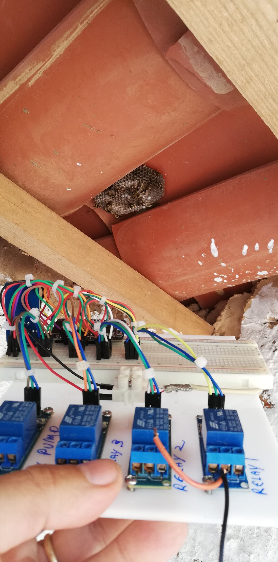
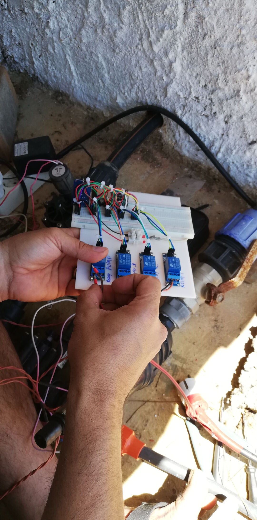
测试之后,我又回到代码做更多定制。
我先看了一系列 YouTube 视频,讲如何真正创建函数,然后开始创建更多函数。
基本上,我去研究了如何减少代码重复,以及如何把值传给函数。
根据现有代码,我创建了这个函数:
void turnOffRelay(int valveHere){
  // wait then turn valve relay OFF
  Serial.print("Waiting ");
  Serial.print(waitTimeValveOff / 1000);
  Serial.println("s before deactivating Valve Relay 3.");
  delay(waitTimeValveOff);
  digitalWrite(valveHere, LOW);
  valveHere = 0;
  Serial.print("*** Valve Relay ");
  Serial.print(valveHere);
  Serial.println("3 turned OFF ***");
}
警告: valveHere = 0; 会在 Serial.print(valveHere); 之前运行,所以无论哪个阀,消息总是输出“Valve Relay 03 turned OFF”。“3”在两条消息里也是写死的。请在把 valveHere 清零之前打印它(或者删掉那一行),并把写死的“3”从字符串中去掉。
每次我想调用这个函数,我就用:
      {
        int valveHere = valveRelay3;
        turnOffRelay (valveHere);
      }
我用 {} 的原因是我必须声明局部变量 valveHere;这样每次调用函数时我只要替换那一小段代码。
从技术上说,调用那个函数只需要这段代码 turnOffRelay (valveHere);,但单独这样不行,因为我总是在用 int valveHere = valveRelay3;
警告: 这些 {} 和局部变量都不需要:引脚会作为参数传入,所以只 turnOffRelay(valveRelay3); 就能完成同样的事。
我还没测试实际行为,但至少能编译 :-)
2020年6月9日
我把它烧录到 ESP32,行为不符合预期。函数一直反复打印。我觉得我需要返回一个变量的状态,但我没这么做。我会尝试用代码 return variable; 来做到这一点,然后再测试,不过在此之前我会再看一遍关于函数的视频,以便更好地理解。
2020年6月13日
唉……好吧,好久没更新了。嗯,最后上传的代码能工作,我也有了一些函数,但我还不满意,因为它在 Arduino 上能跑,在 PlatformIO 上却不行。到目前为止我学到的是,Arduino IDE 在背后做了很多事,而在 PlatformIO 里你需要更详细地配置。
阅读以下内容:
最后我成功用 PlatformIO 把一个文件写入 SPIFFS。我之前已经能用 Arduino 做到,但没真正理解是怎么做到的。现在我想我可能懂了:为此我必须设置 platformio.ini 文件并按照一系列步骤建立目录树,那么来看看:
- 我在 PlatformIO 的“Projects”标签区域创建了一个新项目文件;
- 然后我在与 src 文件夹同级的位置创建了一个 data 文件夹。另一种选择是在 platformio.ini 文件中为 data 文件夹指定不同的路径;
- 然后,在开发板连接的情况下,我运行
pio run -t uploadfs; - 我不得不从 PlatformIO 中移除 Time 库,因为它与 ESPAsyncWebServer 冲突,我是在 这里 找到相关信息的。
成功了。
通过这件事,我开始明白自己之前并不知道自己在做什么。我一开始用的代码把 HTML 放进了 Arduino sketch 里。这让我很困扰。现在有了新的理解,我可以把它与 sketch 文件分开。
然后我找到了这个教程: 使用 SPIFFS 的 ESP32 网络服务器
还有 这个,以防我想用 Arduino IDE 插件来完成上传。
我真希望自己早点更好地理解这些!我在上面花了那么多天!
到目前为止的 C++ 代码。
            /****************************************************************************
            *                                  Aknowledments                           *
            *                                  by LucioPGN                             *
            ****************************************************************************/
           /*  Up to this date: 07th of June 2020 I don't consider myself a programer
            *  so I need to stand on top of giants sholders for my programing projects:
            *  A Portion of this code was based on Rui Santos Code;
            *  A Portion of this code was based on losely based Shakeels code for ESP8266;
            *  A Portion of this code was based on several websites I lost track of....!
            *  My contributions:
            *     -So far I made it work on platformio :), that took me quite a lot of time
            *     -That means:
            *        +created a new project;
            *        +created a folder named data under the main folder (fabfarm_irrigation)
            *        +linked the platformio.ini to the folder of the project + the data folder
            *        +linked the needed libraries to their github repo in the platformio.ini
            *        +found a conflict with time library and ESPAsyncWebserverLibrary can be solved by renaming time library or by removing it
            *        +Made it work with a separate HTML file under the data folder using SPIFFS
            *        +I can load the data to Spiffs inside platformio
            *  Things I still want to program for my final project:
            *    -so far I ported Shakeels code into ESP32;
            *    -simplify the code creating functions rather than repeating the code;
            *    -try to separate the HTML part for a cleaner code (this applies to maybe mix up the other previous code to this);
            *    -Improve the appearance/Interface of the code
            *    -Add readings to HTML
            *    -Add a log of occurrences like over current
            *    -Add more safety for the equipment
            *    -Add a phone interface (APP)
            *    -Add function to set current time
            *    -Add renaming function to each relay so one can relate the relay to the area of interest or at least rename relays to actual areas of the farm.
            *
            ****************************************************************************/


           //Required Libraries
           #include "WiFi.h"
           #include "ESPAsyncWebServer.h"
           #include "SPIFFS.h"
           #include <AsyncTCP.h>

           // Network Credentials
           const char* ssid = "rato";
           const char* password = "imakestuff";

           //Start the Async Web Server listening on port 80
           AsyncWebServer server(80);

           // Set to true to define Relay as Normally Open (NO)
           #define RELAY_NO false

           // Set number of relays, will be used in the array
           #define NUM_RELAYS  4

           // Assign each GPIO to a relay
           int relayGPIOs[NUM_RELAYS] = {26, 25, 33, 32};

           //
           const char* PARAM_INPUT_1 = "relay";
           const char* PARAM_INPUT_2 = "state";

           // Replaces placeholder with button section in your web page
           String processor(const String& var){
             //Serial.println(var);
             if(var == "BUTTONPLACEHOLDER"){
               String buttons ="";
               for(int i=1; i<=NUM_RELAYS; i++){
                 String relayStateValue = relayState(i);
                 //Here parts of the HTML will be parsed to index.html like Relay # followed by its value in variable for the GPIO numbers
                 buttons+= "<h4>Turn on water on " + String(i) + "</h4><h4>Valve (relay) #" + String(i) + " - GPIO " + relayGPIOs[i-1] + "</h4><label class=\"switch\"><input type=\"checkbox\" onchange=\"toggleCheckbox(this)\" id=\"" + String(i) + "\" "+ relayStateValue +"><span class=\"slider\"></span></label>";
               }
               return buttons;
             }
             return String();
           }

           String relayState(int valveRelayNum){
             if(RELAY_NO){
               if(digitalRead(relayGPIOs[valveRelayNum-1])){
                 return "";
               }
               else {
                 return "checked";
               }
             }
             else {
               if(digitalRead(relayGPIOs[valveRelayNum-1])){
                 return "checked";
               }
               else {
                 return "";
               }
             }
             return "";
           }

           void setup(){
             // Serial port for debugging purposes
             Serial.begin(9600);
             // Initialize SPIFFS
             if(!SPIFFS.begin(true)){
               Serial.println("An Error has occurred while mounting SPIFFS");
               return;
             }
             // Set all relays to off when the program starts - if set to Normally Open (NO), the relay is off when you set the relay to HIGH
             for(int i=1; i<=NUM_RELAYS; i++){
               pinMode(relayGPIOs[i-1], OUTPUT);
               if(RELAY_NO){
                 digitalWrite(relayGPIOs[i-1], HIGH);
               }
               else{
                 digitalWrite(relayGPIOs[i-1], LOW);
               }
             }

             // Connect the ESP to the Wi-Fi using the credentials entered before
             WiFi.begin(ssid, password);
             while (WiFi.status() != WL_CONNECTED) {
               delay(1000);
               Serial.println("Connecting to WiFi..");
             }

             // Print ESP32 Local IP Address
             Serial.println(WiFi.localIP());

           /*
           *Now we are going to configure the route where server will be listening for incoming HTTP requests
           and a function that will be executed when a request is received on that route.
           We specify this by calling the "on" method on the server object. With server.on(){};
           As first input, this method receives a string with the path where it will be listening.
           We are going to set it to listen for requests on the "/" route. This could be anything.
           It is basically what you write after the ip adress when in the browser or an APP.
           This website has a great explanation of the ESP32 Arduino: Asynchronous HTTP web server
           https://techtutorialsx.com/2017/12/01/esp32-arduino-asynchronous-http-webserver/
           So...
           - First parameter here is: "/" thats the root directory.
           - Second parameter is HTTP_GET thats an enum of type WebRequestMethod a method defined in the library here --> https://github.com/me-no-dev/ESPAsyncWebServer/blob/63b5303880023f17e1bca517ac593d8a33955e94/src/ESPAsyncWebServer.h
           - Third parameter is a the function AsyncWebServerRequest
           So there is this c++ lambda function used here. My litle understanding is that they are locally declared unamed function this means they dont have a name and are declared locally :-)
            I don't grasp the concept fully haha.
            the syntax is [captures](params){body} where in here [] is empity
           */

             // Route for root / web page
             server.on("/", HTTP_GET, [](AsyncWebServerRequest *request){
               request->send(SPIFFS, "/index.html", String(), false, processor);
             });

            // Send a GET request to <ESP_IP>/update?relay=<inputMessage>&state=<inputMessage2>
             server.on("/update", HTTP_GET, [] (AsyncWebServerRequest *request) {
               String inputMessage;
               String inputParam;
               String inputMessage2;
               String inputParam2;
               // GET input1 value on <ESP_IP>/update?relay=<inputMessage>
               if (request->hasParam(PARAM_INPUT_1) & request->hasParam(PARAM_INPUT_2)) {
                 inputMessage = request->getParam(PARAM_INPUT_1)->value();
                 inputParam = PARAM_INPUT_1;
                 inputMessage2 = request->getParam(PARAM_INPUT_2)->value();
                 inputParam2 = PARAM_INPUT_2;
                 if(RELAY_NO){
                   Serial.print("NO ");
                   digitalWrite(relayGPIOs[inputMessage.toInt()-1], !inputMessage2.toInt());
                 }
                 else{
                   Serial.print("NC ");
                   digitalWrite(relayGPIOs[inputMessage.toInt()-1], inputMessage2.toInt());
                 }
               }
               else {
                 inputMessage = "No message sent";
                 inputParam = "none";
               }
               Serial.println(inputMessage + inputMessage2);

               //This is the last part of the lambda function.
               //This method receives as first input the HTTP response code, which will be 200 in our case.  This is the HTTP response code for "OK".
               request->send_P(200, "text/plain", "OK");
             });

             // Start server here
             server.begin();
           }

           void loop(){

           }
警告: hasParam(PARAM_INPUT_1) & hasParam(PARAM_INPUT_2) 使用的是 & 的按位形式;逻辑与是 &&。对两个 bool 来说结果恰好相同,但它不会短路,正确的运算符是 &&。
到目前为止的 HTML 代码。
<!DOCTYPE HTML><html>
<head>
  <meta name="viewport" content="width=device-width, initial-scale=1">
  <style>
    html {font-family: Arial; display: inline-block; text-align: center;}
    h2 {font-size: 3.0rem;}
    p {font-size: 3.0rem;}
    body {max-width: 600px; margin:0px auto; padding-bottom: 25px;}
    .switch {position: relative; display: inline-block; width: 120px; height: 68px}
    .switch input {display: none}
    .slider {position: absolute; top: 0; left: 0; right: 0; bottom: 0; background-color: #ccc; border-radius: 34px}
    .slider:before {position: absolute; content: ""; height: 52px; width: 52px; left: 8px; bottom: 8px; background-color: #fff; -webkit-transition: .4s; transition: .4s; border-radius: 68px}
    input:checked+.slider {background-color: #2196F3}
    input:checked+.slider:before {-webkit-transform: translateX(52px); -ms-transform: translateX(52px); transform: translateX(52px)}
  </style>
</head>
<body>
  <h2>Fab Farm Irrigation System</h2>
  %BUTTONPLACEHOLDER%
<script>function toggleCheckbox(element) {
  var xhr = new XMLHttpRequest();
  if(element.checked){ xhr.open("GET", "/update?relay="+element.id+"&state=1", true); }
  else { xhr.open("GET", "/update?relay="+element.id+"&state=0", true); }
  xhr.send();
}</script>
</body>
</html>
它目前看起来是这样:
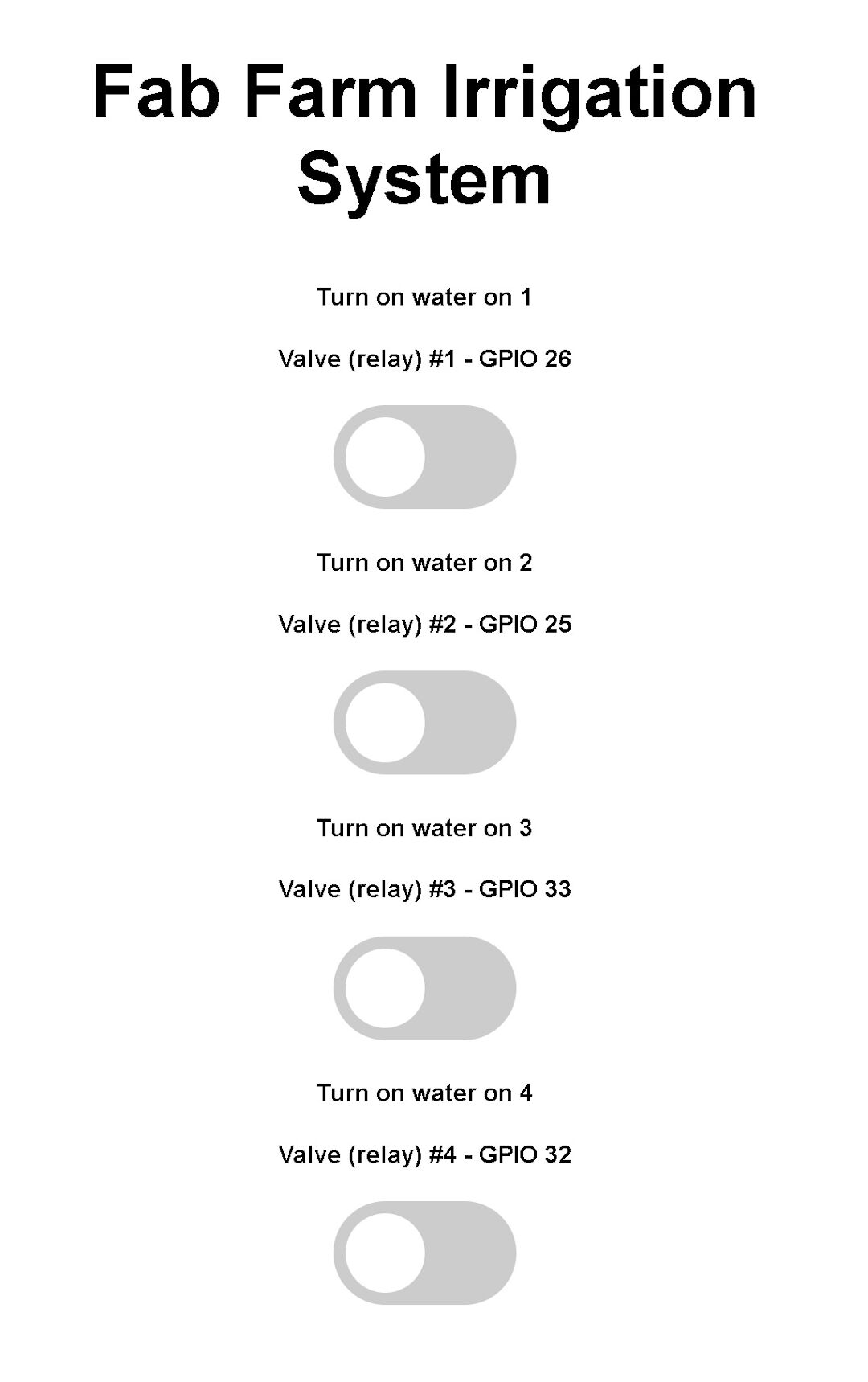
现在的外观和代码与 Random Nerd Tutorials 网站上用 ESP32 控制继电器的内容非常相似。
与原代码的主要区别是,它运行在 VS Code 的 PlatformIO 上,而且 HTML 文件使用了单独的文件夹结构,该文件被写入 ESP 的 SPIFFS。
2020年6月14日
在经历了所有这些个人突破之后,我决定需要从零开始写代码,只使用农场现有灌溉系统的总体算法。原因是代码太乱、重复太多;昨天那些资料里的做法让我意识到,把功能一个一个加到最新代码里,比从农场正在运行的代码重新编写一切要快。
今天我会尝试添加更新后的信息,比如温度和湿度。我再次基于 Rui Santos 的工作 ,在这个关于气象站的页面上。用这种方法,我相信我也能用 RTC 时钟加入一天中的时间。
连接 DHT22 的原理图来自他的网站:
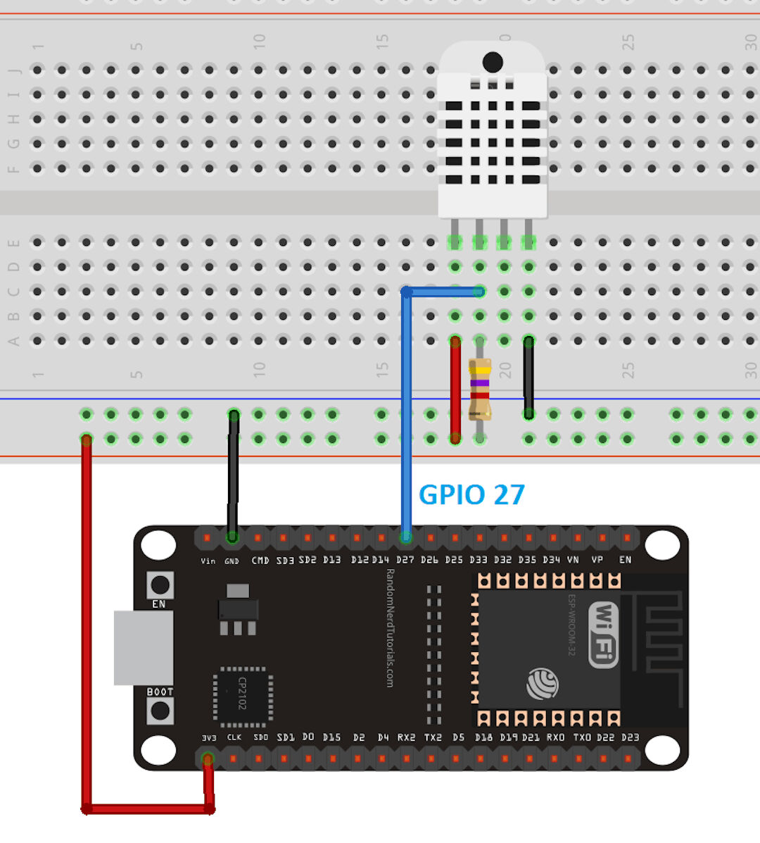
它使用一个 4.7k 欧姆电阻作为上拉电阻。
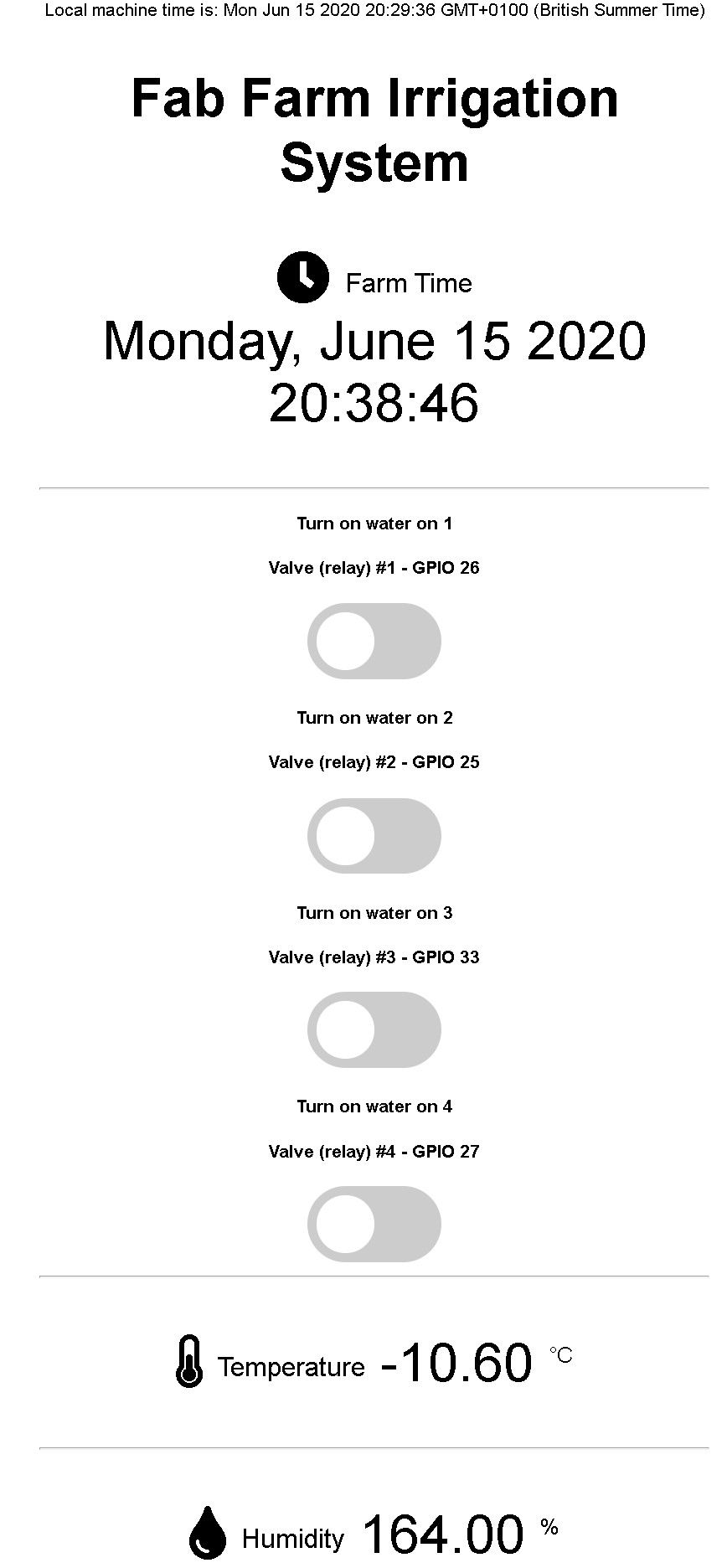
经过一番工作,页面现在看起来是这样:
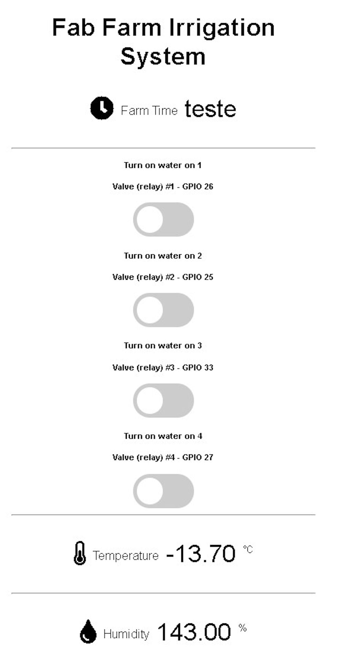
我认为温度现在变成负数,是因为温湿度传感器坏了,或者我的接线有点松。我相信,等我自己铣一块电路板并焊好所有东西,而不是插在面包板上,这会可靠得多。不管怎样,我现在能读到数值,也能在网页界面上显示它们。
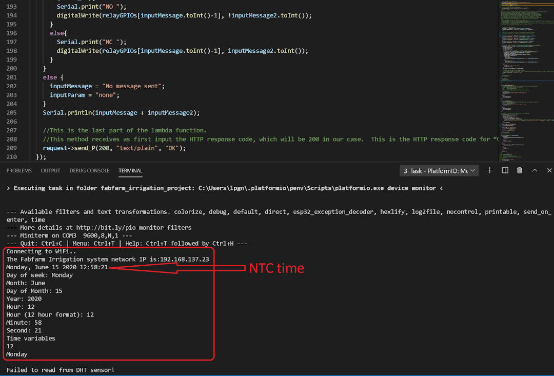
在串口监视器上,我目前能显示互联网时间和网络信息;现在我需要找到一种方法获取时间值并在网页界面中显示。目前我在代码里发送 TESTE 这个词,显示出来的就是它,而不是时间。
2020年6月15日
今天我会专注于把时间显示在网页界面上,也许还会创建一个在指定时间打开继电器的函数。
20:44 更新:
- 经过一整天的尝试,我成功显示了机器时间和灌溉系统(ESP32)的时间。
现在界面看起来是这样:
我长大以后想当程序员 :-),而不是把一整天花在别人几行代码就能搞定的东西上!
多亏了一位圣人,我的痛苦才结束,靠的是 这个回答,在 Arduino Stack Exchange 上。
下面是当时贴出的原始函数:
void printLocalTime()
{
  time_t rawtime;
  struct tm timeinfo;
  if(!getLocalTime(&timeinfo))
  {
    Serial.println("Failed to obtain time");
   return;
  }
  char timeStringBuff[50]; //50 chars should be enough
  strftime(timeStringBuff, sizeof(timeStringBuff), "%A, %B %d %Y %H:%M:%S", &timeinfo);
  //print like "const char*"
  Serial.println(timeStringBuff);

  //Optional: Construct String object
  String asString(timeStringBuff);
}
经过小幅修改,把它从 void 函数变成 String 函数,并添加一个 return,我把它命名为“timeAsAString”:
//this function was found here https://arduino.stackexchange.com/questions/52676/how-do-you-convert-a-formatted-print-statement-into-a-string-variable
//I did a minor change so instead of a void function it now returns a string to be used to show time in the webinterface
String printFarmTime()
{
  time_t rawtime;
  struct tm timeinfo;
  getLocalTime(&timeinfo);
  char timeStringBuff[50]; //50 chars should be enough
  strftime(timeStringBuff, sizeof(timeStringBuff), "%A, %B %d %Y %H:%M:%S", &timeinfo);
  //print like "const char*"
  Serial.println(timeStringBuff);

  //Construct to create the String object
  String timeAsAString(timeStringBuff);
  return timeAsAString;
}
警告: 这个版本去掉了 if(!getLocalTime(&timeinfo)) 检查,所以如果 NTP 还没有响应,它会格式化出一个空的(垃圾)时间。保留这个检查,并在失败时返回类似 "time not set" 的内容。
那么,既然这个解决了,我会尝试创建按照计划时间开关继电器的函数。看看我今天能不能完成……
结论
至于这项作业,我对目前所处的进度很满意,但我会为最终项目进一步开发网页界面。你可以从这项作业结束的地方继续,往下看 项目开发页面里的 2020年6月16日。
我和我的朋友 Jeff Knight 开了一次会,他是一名专业程序员,他帮我起草了一份计划草图,说明我想把最终项目带到哪里、我们现在在哪里。它在下面,是我为最终项目所写软件创建的 GitHub 页面的 README.md 的一部分。
下面的视频展示了功能。
计划草图
HTML <--> JavaScript <--> C++
| 网页界面 | 微处理器 (ESP32) |
|---|---|
| 按区域设置: | 接收: |
| [ ] 开始时间 | [ ] 开始时间 |
| [ ] 循环时长,最长 1 小时 | [ ] 循环时长 |
| [ ] 覆盖按钮 | |
| 显示 | [ ] 将以上信息存入 SPIFFS(csv?) |
| [x] 一天中的时间 | 逻辑测试: |
| [x] 湿度 | 持续检查:({ |
| [x] 温度 | - 我(“区域 x”)是否处于开启窗口(“时间 + 时长”)? |
| 是:“确保”我处于开启状态 | |
| 否:确保我处于关闭状态 | |
| [ ] 当前区域程序已存储 | -等待覆盖按钮,如果收到就中断循环 |
| [ ] 覆盖按钮 | 等待覆盖按钮,随时开启/关闭 |
| [ ] 当前区域状态(ON/OFF) | 更新/发送当前情况: |
| [x]一天中的时间; | |
| [x]区域状态(ON/OFF) | |
| [x]传感器信息(湿度/温度) | |
微处理器
- 运行:网络服务器
- /index.html:显示 index
- /temp.html:占位符
- /farmtimenow:返回时间
- /slider:
- /temperature:返回温度
- /humidity:返回湿度
- /update: 设置 值
启动时:
- 我们从 csv 文件读取
- 把信息保存在内存中,以便在循环里对照检查(这是那个窗口吗?)
- 我们还要告诉 HTML 它应该预先设置哪些配置
问题:
- 如果微控制器断电,我们可能会丢失状态。因此我们需要一种把设置持久化到磁盘的方法
- 我们需要保存什么?
- N 个区域,以及每个区域的:
- 名称
- 开始时间(时间戳)
- 循环时长
- 当前状态(开/关)<-- 这可以计算出来:如果我们处于开始和结束之间,那就应该是开!
- N 个区域,以及每个区域的:
csv 文件:zone1, 20200101 00:00:00.0000, 1234, 1, 12 zone2, 20200101 00:00:00.0000, 1234, 1, 16 zone3, 20200101 00:00:00.0000, 1234, 1, 18
我什么时候会动它?
- 变更时(新信息)
- 重启时
- 就这样
- 其他时候,它在内存里,你已经知道了(!)
读取 csv 文件。对每一行:按 ',' 拆分成数组 ....
我们需要保存状态:
- csv 或 sqlite
这是最终项目网页界面的第一版计划,等你读到这段文字时,它已经发展得更多了。