Computer-Controlled Cutting
Group Assignment
- Characterize your laser cutter's focus, power, speed, rate, kerf, and joint clearance
- Document your work (individually or in group)
Individual Assignment
- Design, laser cut, and document a parametric press-fit construction kit, which can be assembled in multiple ways. Account for the laser cutter kerf.
Learning Outcomes:
- Demonstrate and describe parametric 2D modeling processes
- Identify and explain processes involved in using the laser cutter
- Develop, evaluate, and construct the parametric construction kit
Have You:
- Linked to the group assignment page
- Explained how you parametrically designed your files
- Documented how you made your press-fit kit
- Included your hero shots
Vinyl Cutting
Individual Assignment
- Cut something on the vinyl cutter
Learning Outcomes:
- Identify and explain processes involved in using the vinyl cutter
Have You:
- Documented how you made your vinyl cutting
- Included your original design files
- Included your hero shots
Index
- Tools Used
- Software Used
- Files
- Introduction
- Group Assignment
- Characterization of My Laser Cutter
- Press-Fit Construction Kit
- Vinyl Cutter
Tools Used
- Laser cutter made during machine design week
- Silhouette Cameo
Software Used
Files
- Press-fit construction kit: Zip file with the SolidWorks file, DXF file, and laser cutter G-code
- Test Files
Warning
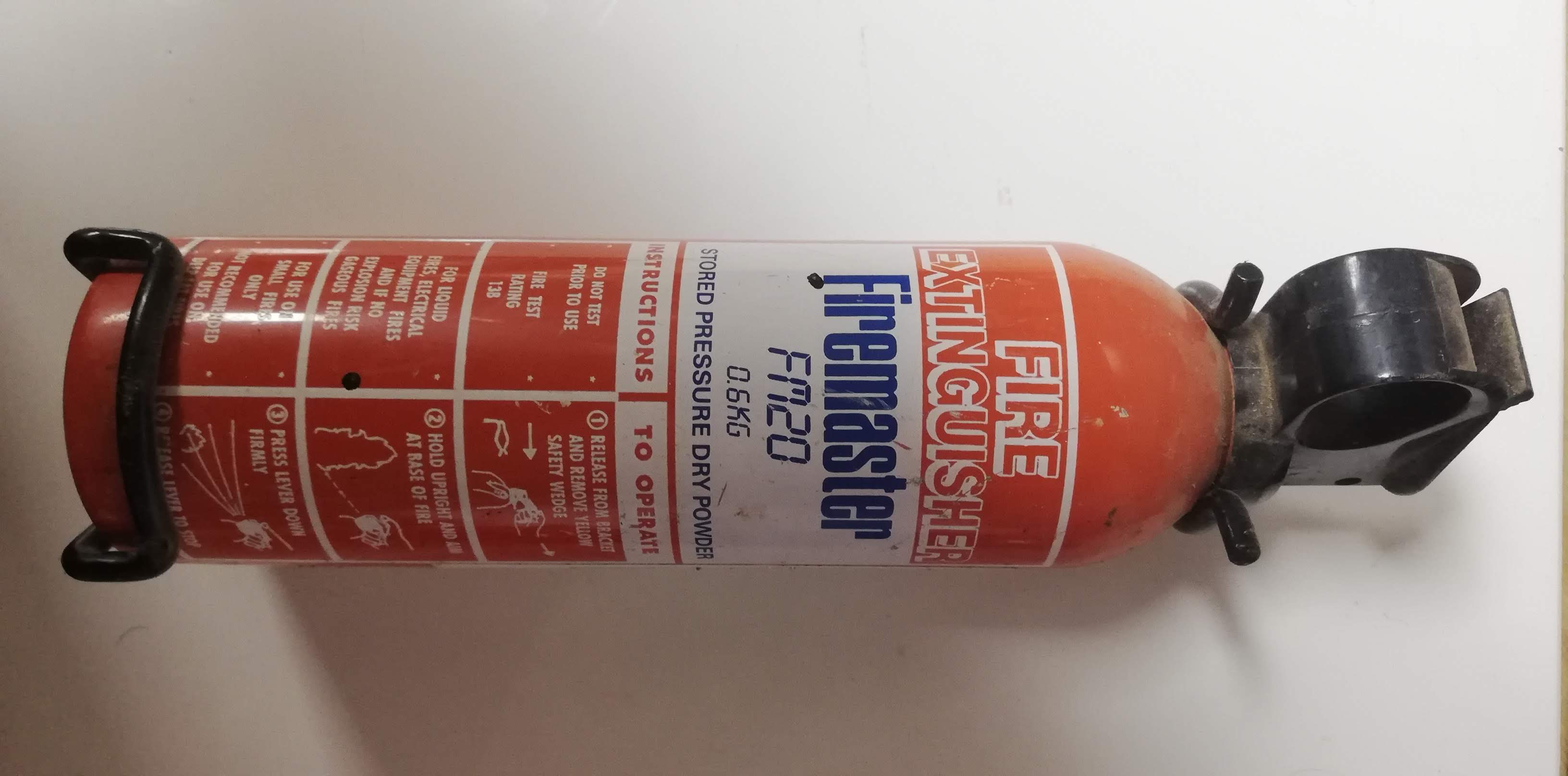
Wear safety glasses, make sure you know where and how to operate the fire extinguisher, and never leave the laser unattended!
Risk of Fire
The laser cutter is a machine that can catch fire if not properly monitored. If everything is working correctly, it won't, but if there is a failure and the laser stays in the same place or if the air assist stops working, there is a high risk of fire. For this reason, never leave the laser unattended.
Laser Radiation
The laser beam can blind you or burn your skin in nanoseconds. For this reason, never operate it with the lid open, and always wear the safety glasses for the type of laser you are using.
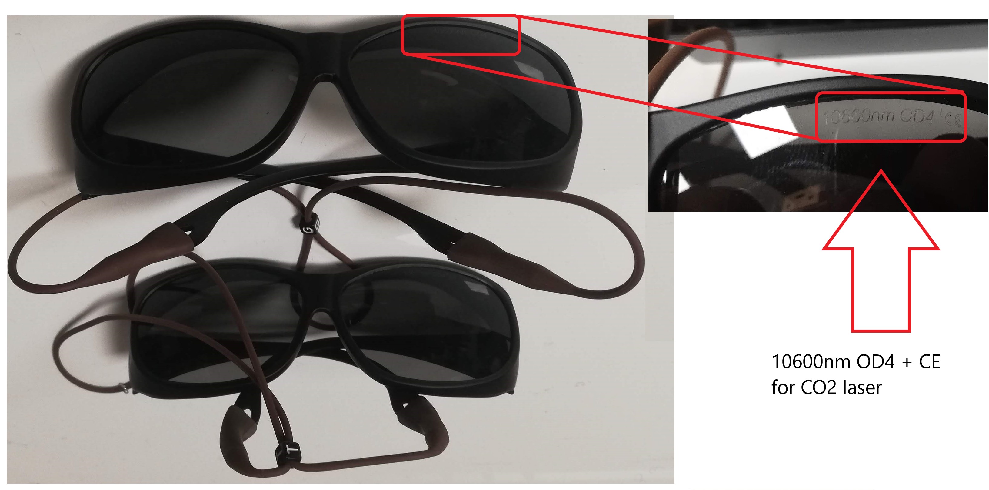
CO2 laser cutters are typically 10,600 nm wavelength. In our lab, these are the correct glasses.
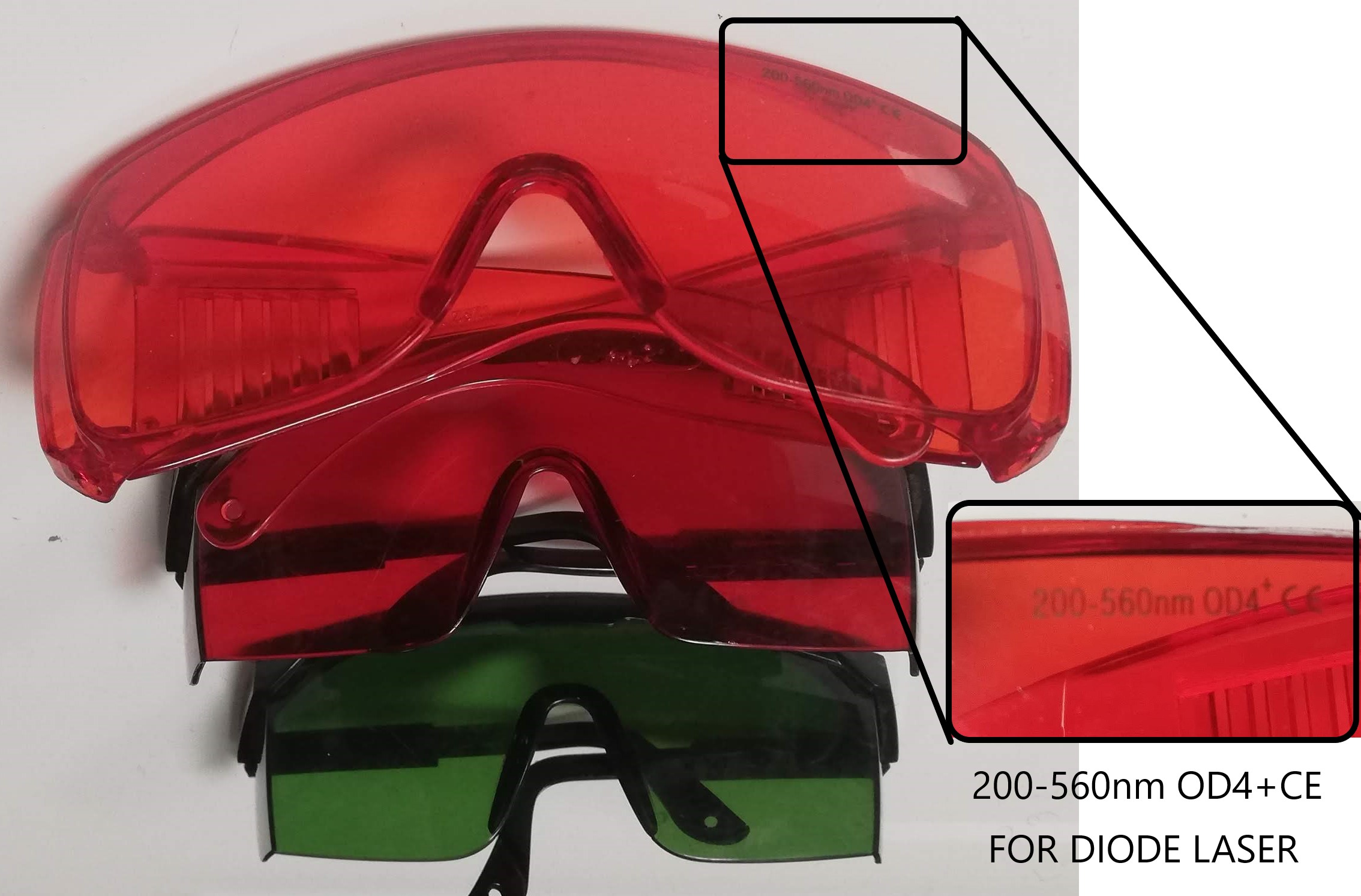
Diode laser cutters are typically in the range of 200-550 nm wavelength. In our lab, these are the correct glasses.
Introduction
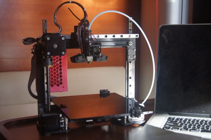
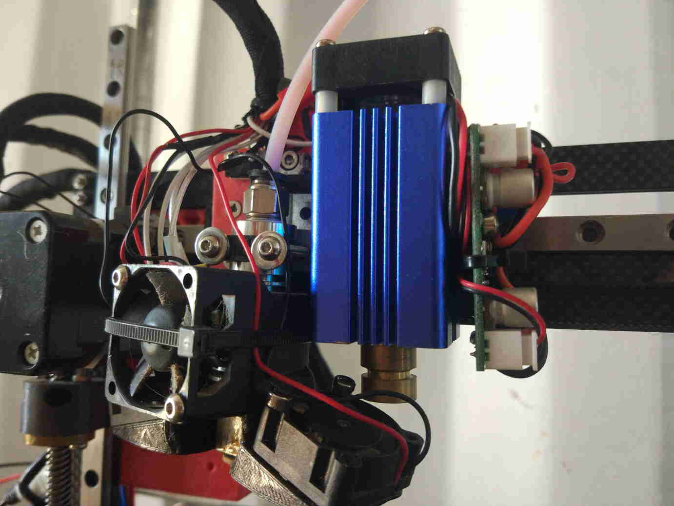
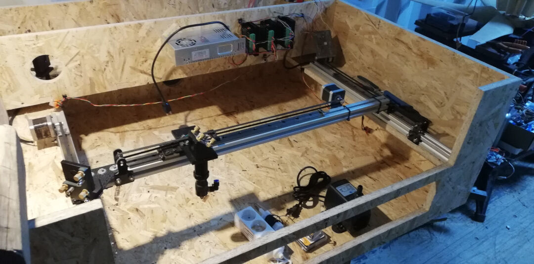
In this assignment, I was going to use a 3D printer I designed and made, which I then upgraded with a 2-watt diode laser. However, I ended up designing and making a CO2 laser cutter as I did not want to finish this course without such a machine in my lab. I am really happy with my machine. It is showing amazing results even as a DIY machine.
I will be testing its capabilities and pushing it to its limits to better understand its capabilities and limitations.
On the vinyl side of the assignment, I will be using a Silhouette Cameo and documenting its results.
Group Assignment
Visit the group assignment page for other assignments. This week's group assignment I am doing by myself as I am alone in the lab.
Characterization of My Laser Cutter
- Work area: 400 x 290 mm
- Height: 150 mm
- Laser power: 50 W
- Focus and Kerf
- Power and Speed
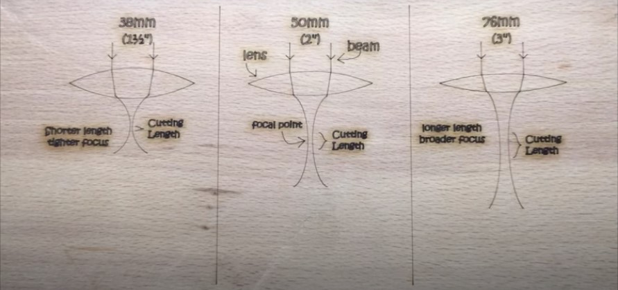
The lens I use in my laser is a 20 mm diameter lens with a 50.8 mm focal length. This means I should keep the height from the lens around that measurement.
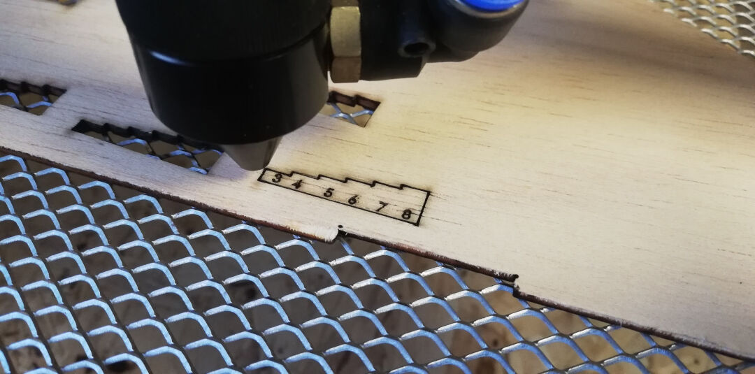
It would be a challenge to measure the focal distance every time. For this reason, I designed the ramp below. This will allow the laser to trace a line from the highest point of the ramp (0 mm from the tip of the laser) to the lowest point of the ramp.
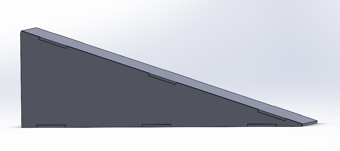
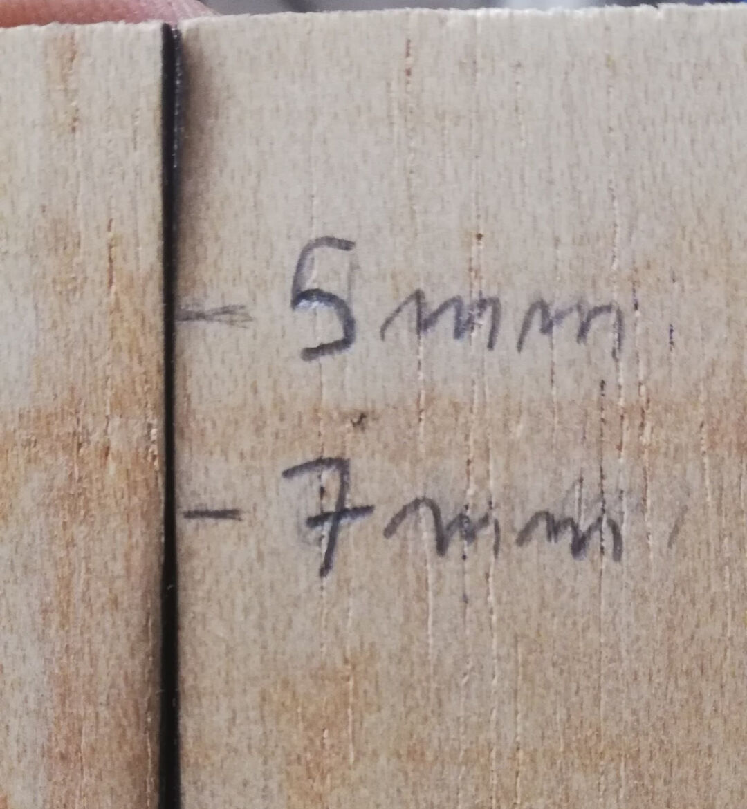
The result from the test is that I should use the distance of 5 to 7 mm from the material top to the tip of the laser head.
With the trace done, I started measuring with a caliper and a square the most focused area of the trace.
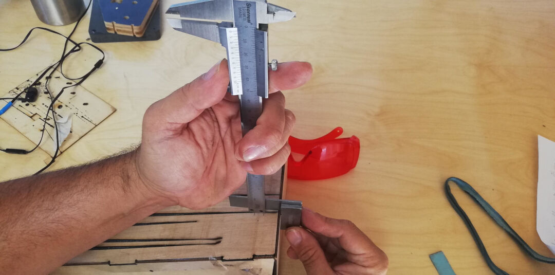
The result is a range from 5 to 7 mm.
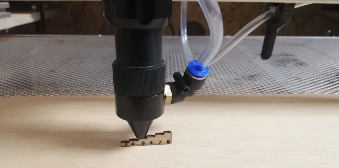
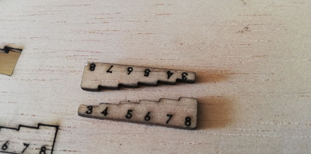
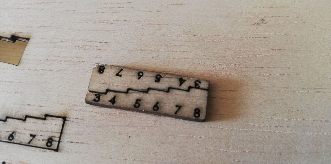
To easily measure the encountered optimal distance, I designed small steps of 1 mm starting from 3 mm ending on 8 mm.
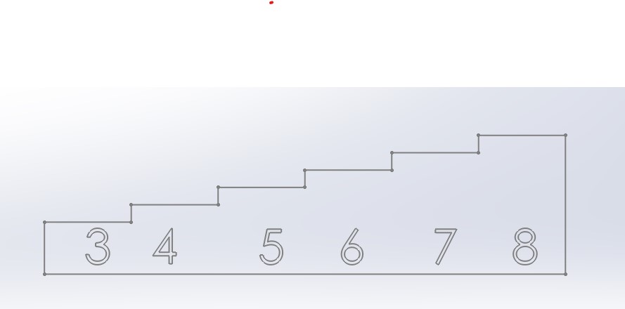
I then laser cut it.
Placing the nozzle on top of the desired height gives a consistent measurement across the surface of the material.
Measuring the kerf was simple. I used the previous template and the hole left by the cut. The difference is the kerf or the thickness of the removed material by the laser beam.
The inside measurement was 8.1 mm
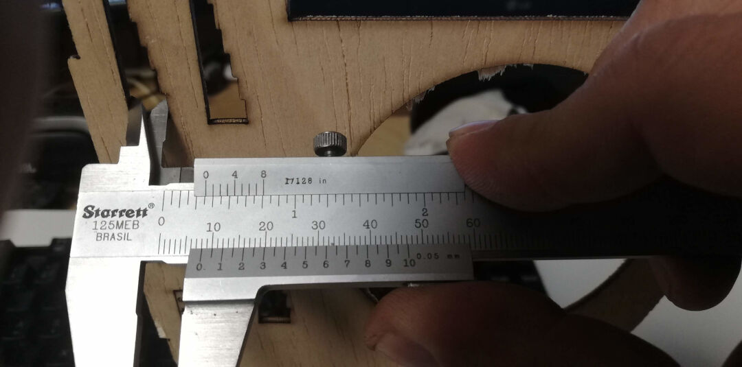
The outside measurement was 7.9 mm, which means the kerf is 0.2 mm / 2 = 0.1 mm.
I really like the fact that it fits perfectly!
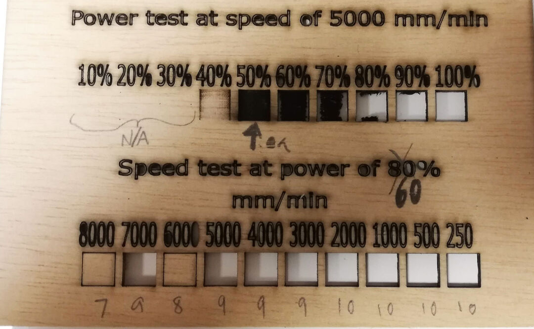
The power test above was done with a speed of 5000 mm/min on a 2.7 mm plywood. The power I chose as most suitable for this speed is 50%.
The speed test above was done on a 2.7 mm plywood, with power set at 60%. Even with the low power, the laser was able to cut on almost all speeds tested. To be on the safe side, I would choose to cut at 5000 mm/min with the power at 60% for this thickness of plywood.
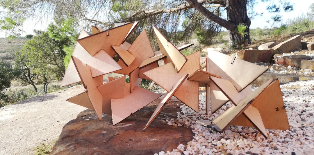
Press-Fit Construction Kit
For this assignment, I will use 2D design from SolidWorks. This is done within the sketches. SolidWorks is a parametric design tool able to dynamically change its features with a change of a variable.
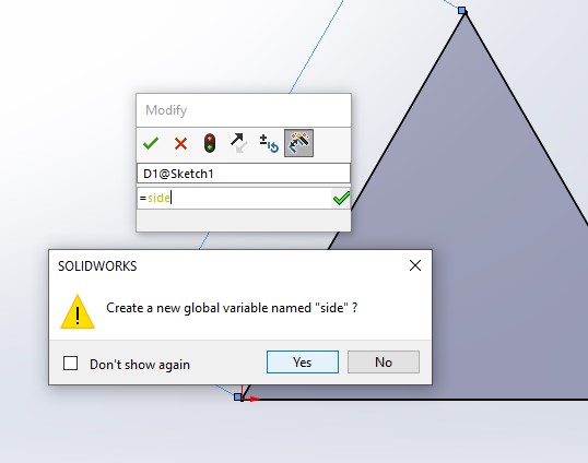
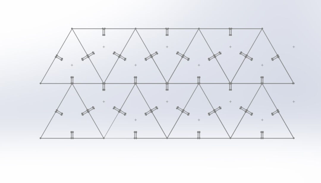
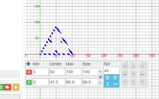
I started by creating a sketch. I then drew a triangle.

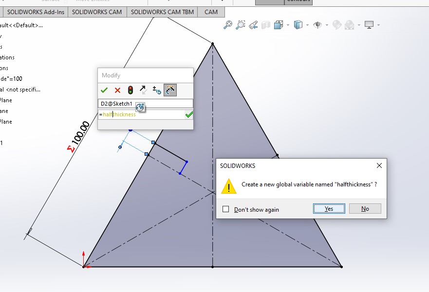
Next, I started creating global variables. While adding dimensions, I simply typed "equal" and then named the variables. Next, I confirmed the creation of the global variable.
I kept drawing more features to the sketch, adding parameters to each measurement.
Next, I created a pattern with the desired feature that will be the connection of the piece.
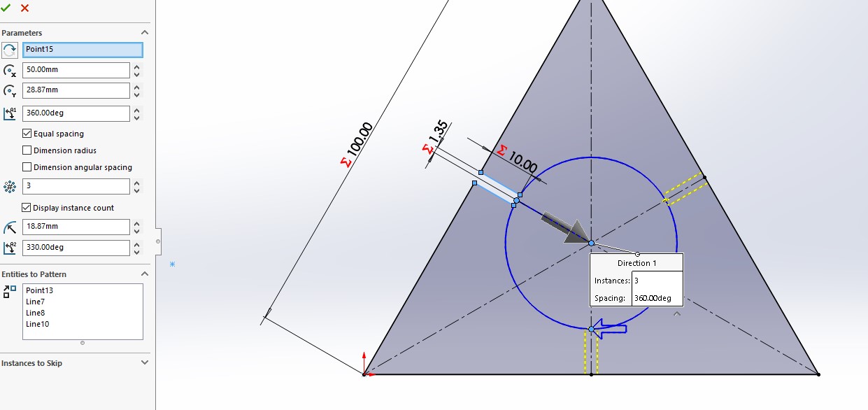
In this panel, I am able to edit each variable, changing it and dynamically changing the model.
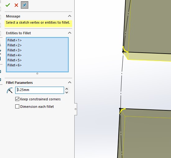
I added a little fillet here to allow a smooth coupling of the parts.
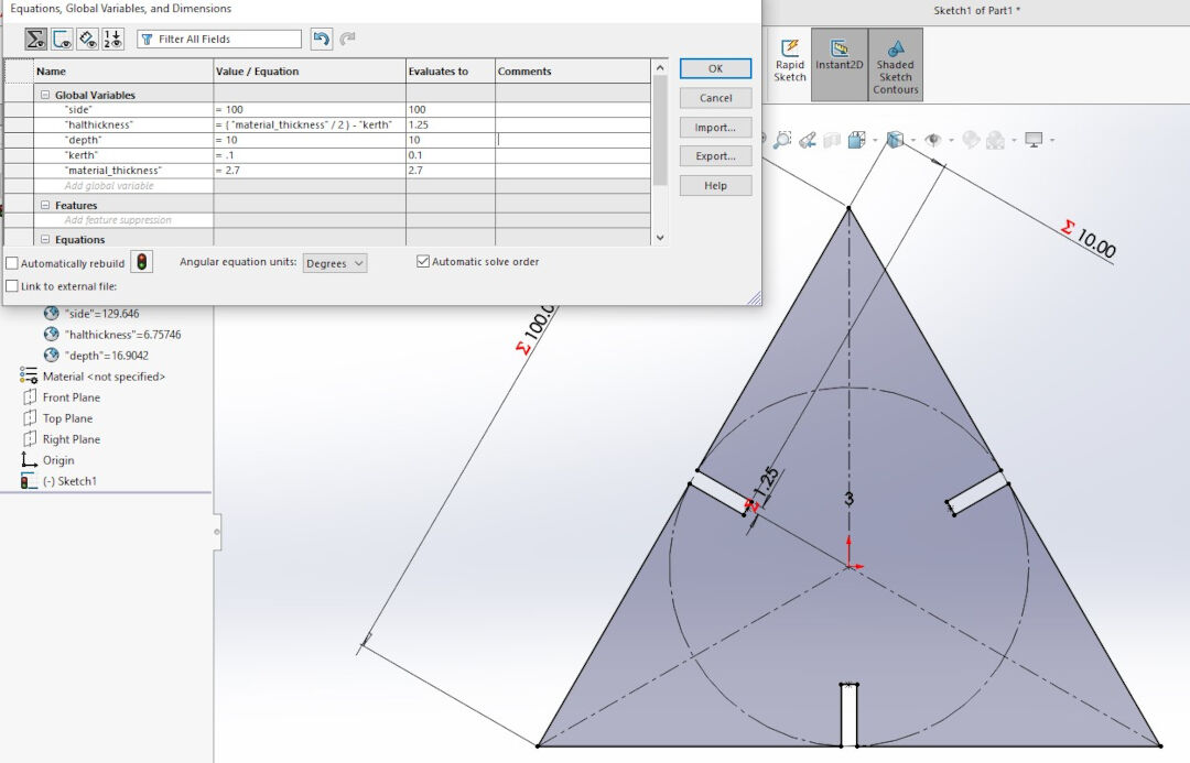
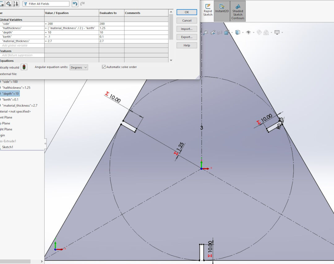
I proceeded to create formulas. This will allow me to change the opening by changing one variable, and it will take into account the kerf size.
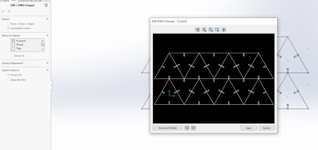
Next, I prepared the kit for exporting as a DXF file.
In SolidWorks, in order to export a sketch, keep it open, then click on save as and do not rebuild, then choose the format, in my case, DXF, and finish the export process.
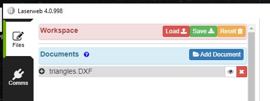
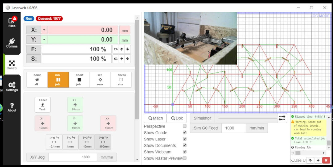
In LaserWeb, add the document. Next, drag the added document to the gray area below.
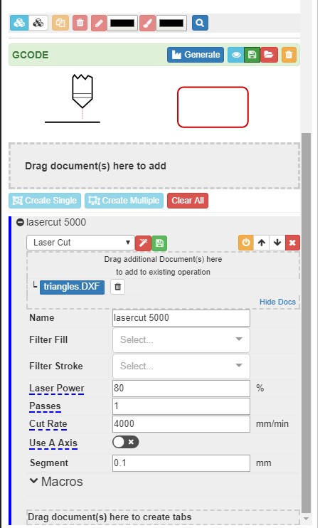
After dragging the file, a dialog with configurations will open. The software sometimes won't prevent you from creating invalid G-code. This means if some parameters are filled up, it will not warn about them.
For this job, since it's a cut, I used one of my presets with the speed 4000 mm/min, power 80%, and segment 0.1.
Next, I positioned the object using either the arrows or the coordinates.
Here I show that I ended up multiplying the triangles in SolidWorks and then reopened the file.
In this picture, it is also possible to see the middle top of the web camera that is positioned on top of the laser so I don't need to keep my eyes on it. Even though I wear protective glasses, I still prefer not to look at the laser while it is still without a cover.
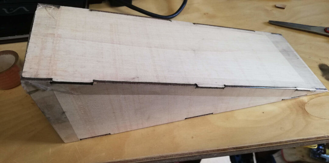
I then removed it from the machine and piled it to start inspecting and assembly.
Just a pile.
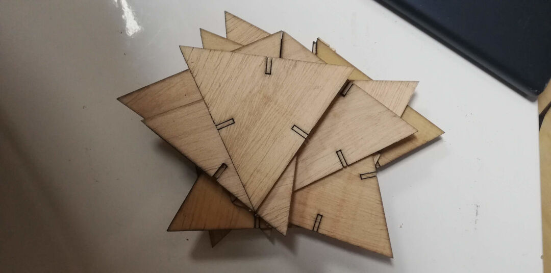
I then started assembly, and it fits perfectly.
Vinyl Cutting
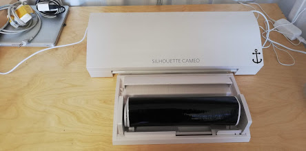
The vinyl cutter we have in the lab is the Silhouette Cameo 3. It's a nice, affordable, easy-to-use vinyl cutter.
It comes with the software Silhouette Studio.

Learning Outcomes:
- Identify and explain processes involved in using this machine.
- Creating the File
- Selecting a File from Library
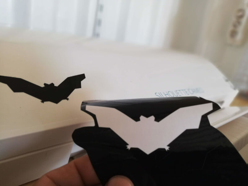
As a warm-up and because we are near Halloween, I decided to cut something my kids could use.
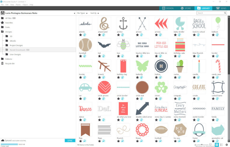
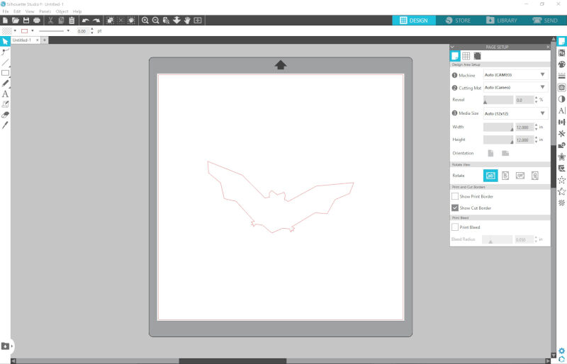
I chose the bat from the library.
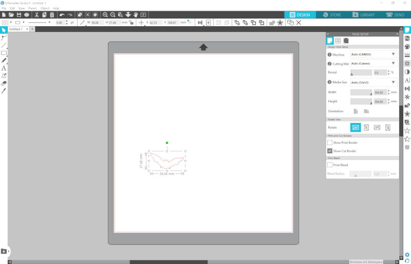
Then using Ctrl+C and Ctrl+V, I copied and pasted the bat several times.
I then selected all the pasted bats.
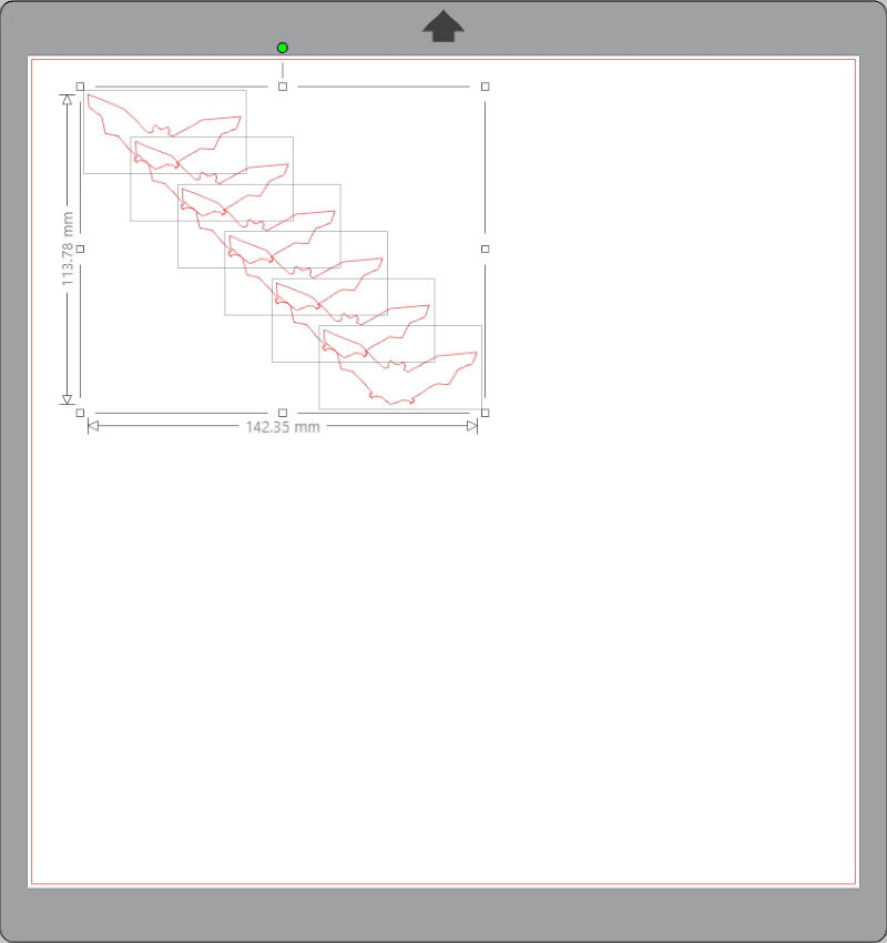
With the selected drawings, it is possible to align the drawings uniformly.
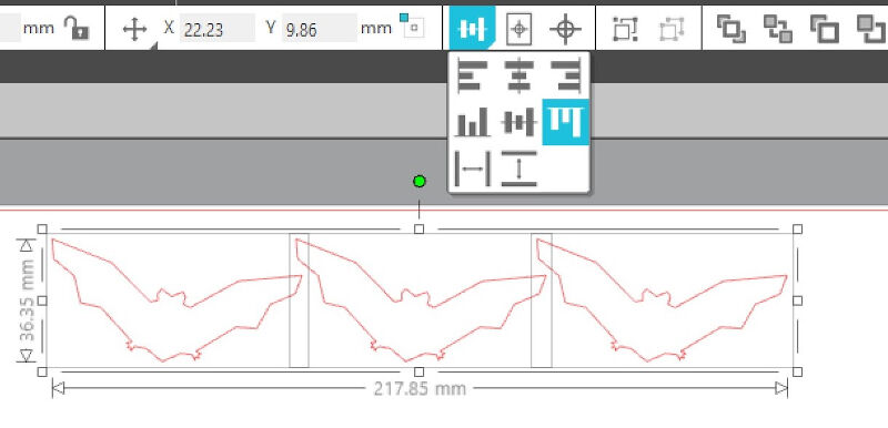
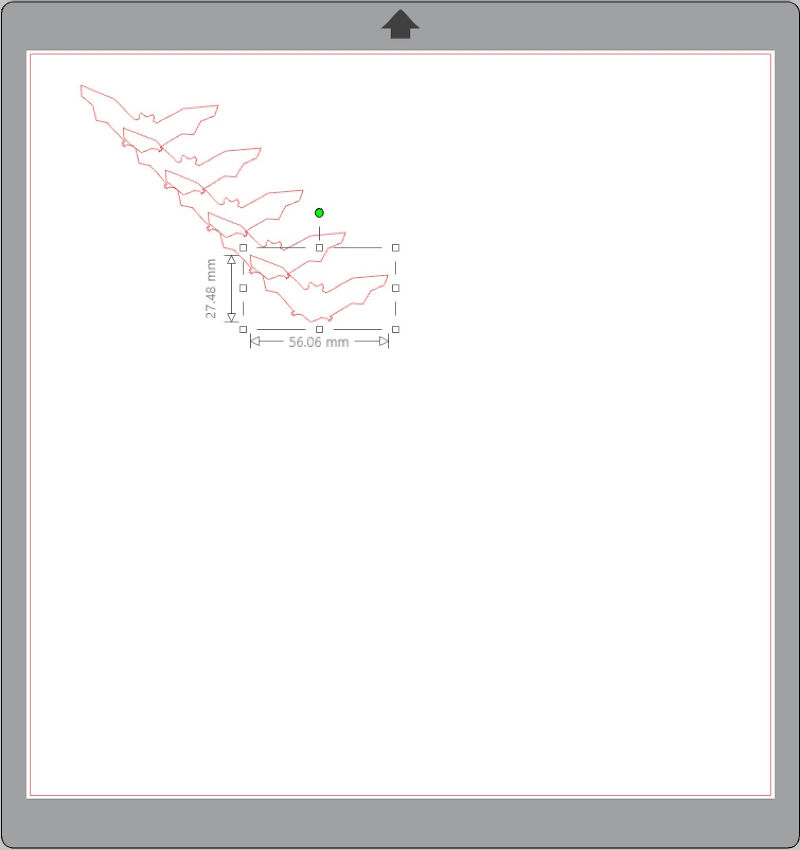
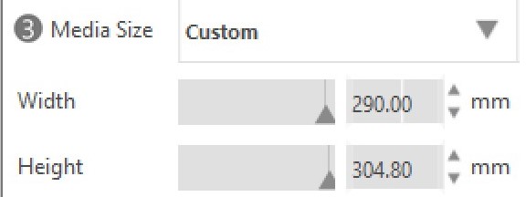
I then selected the vinyl size.
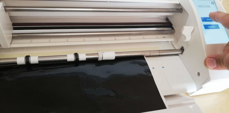
I then pasted again some more bats and started setting up the job. This machine is capable of automatically setting the thickness of the material, but the option autoblade must be selected.
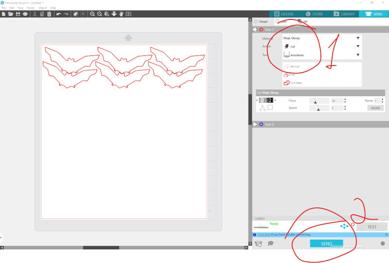
I then aligned the vinyl and lifted the roll that drags the material.
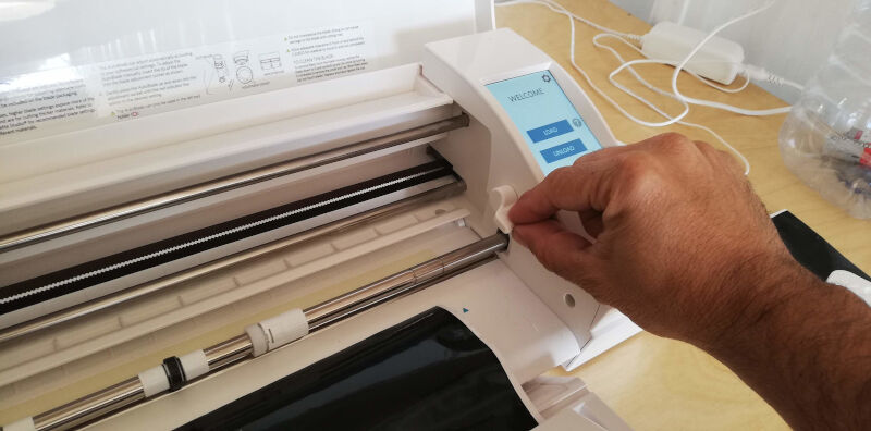
Using the screen, I fed the material a little bit.
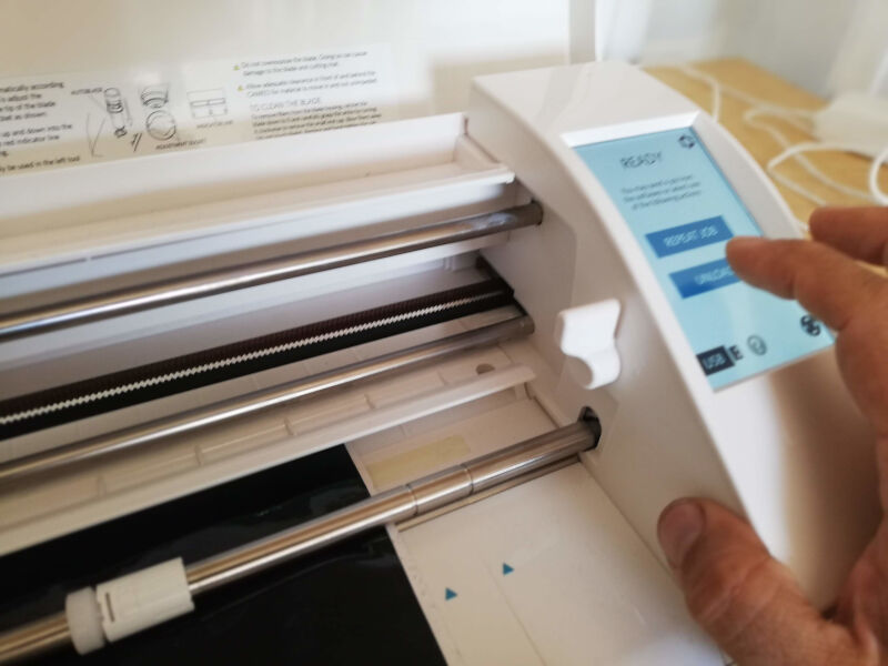
At this point, I could either connect a USB directly to the machine or use the USB.
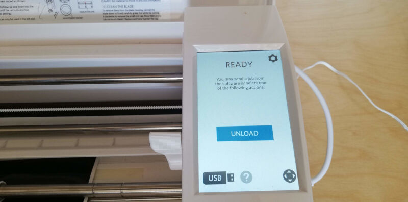
I pressed start, and in minutes the bats are cut.
For a project as simple as that, it is sufficient to just peel the adhesive out of the protective paper and stick it everywhere!