Computer-aided Design
Individual assignment
- Model (raster, vector, 2D, 3D, render, animate, simulate, ...) a possible final project, and post it on your class page.
Learning outcomes:
- Evaluate and select 2D and 3D software
- Demonstrate and describe processes used in modeling with 2D and 3D software
Have you:
- Modeled experimental objects/part of a possible project in 2D and 3D software
- Shown how you did it with words/images/screen-shots
- Included your original design files
Tools used
- Caliper
- Camera
Software Used
- SolidWorks
- Fusion 360
- BCNC
- Inkscape
Design files
- Inkscape file
- incubator SolidWorks source files on Fabacademy Gitlab
- Egg original file and STL file.
- Crate original file and STL file.
- Fusion 360 file of wood patch (extra credit) :-)
Video render and link of my possible final project
Introduction
In this assignment, I will review three software tools: Inkscape, SolidWorks, and Fusion 360. Secondly, I will model a possible final project with SolidWorks.
Inkscape
I have used Inkscape extensively in the past, especially with a diode laser cutter add-on, but not so much recently.
My most used feature of Inkscape was its ability to transform a raster image into a vector. Let's see how it works.
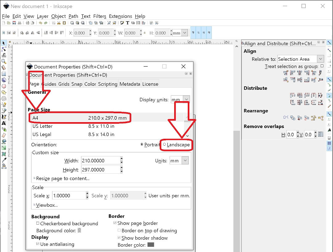
Initially, I go to File -> Document properties and change the paper size. It will serve as a size reference for me as it's possible to edit outside of these boundaries. In my case, I chose A4 Landscape mode.
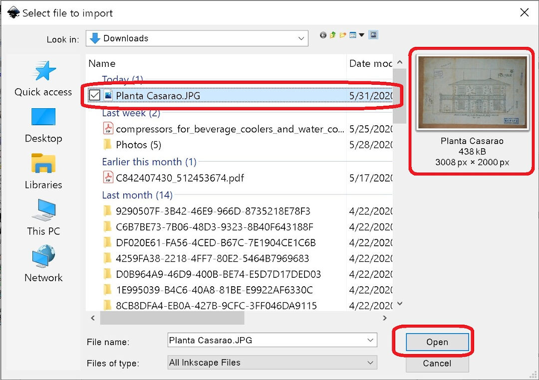
Next, I import the file with Ctrl+I or by clicking on File -> Import, then choose the file I want to import and open it.
Next, this dialog opens, and I click OK.

The image is now open. One can then click on the Layers area and the plus sign to add a layer. That's useful to split the edition into different layers to organize the editing of the file. I ended up doing it later after the next steps.

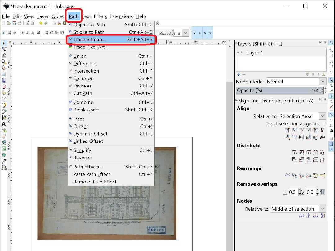
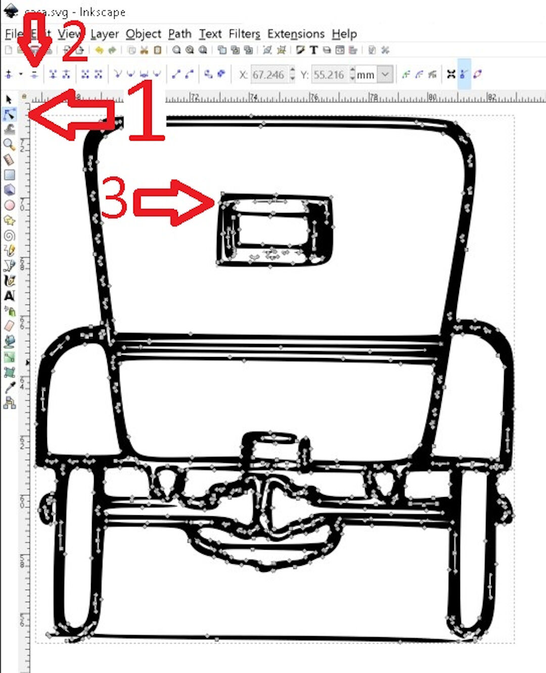
Next, I select Path -> Trace Bitmap or (Shift+Alt+B).
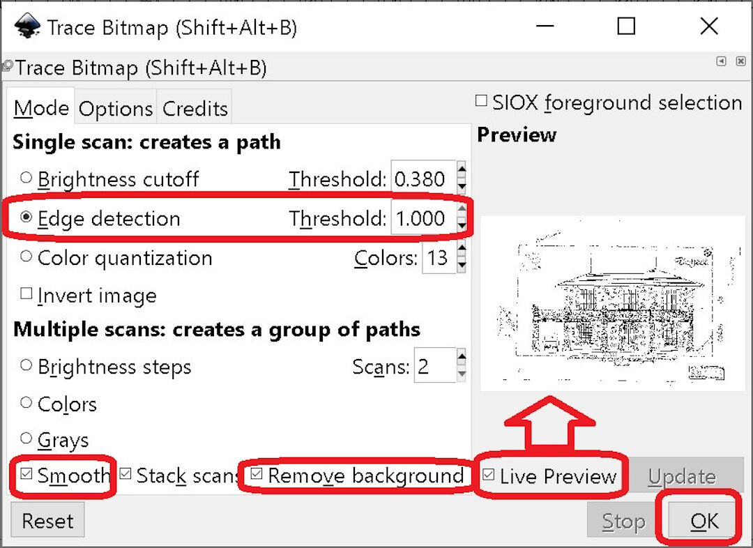
This feature will trace the outlines of the raster image and convert it to a vector image. I then select Edge detection and a threshold (1), then Smooth, remove background, and Live Preview. Clicking on Live Preview gives an idea of how the settings will affect the conversion, so it can be useful. Finally, I click OK.
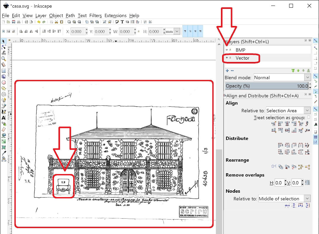
As I mentioned earlier, I can now create layers and name them. Next, I move the original drawing to one of the layers.
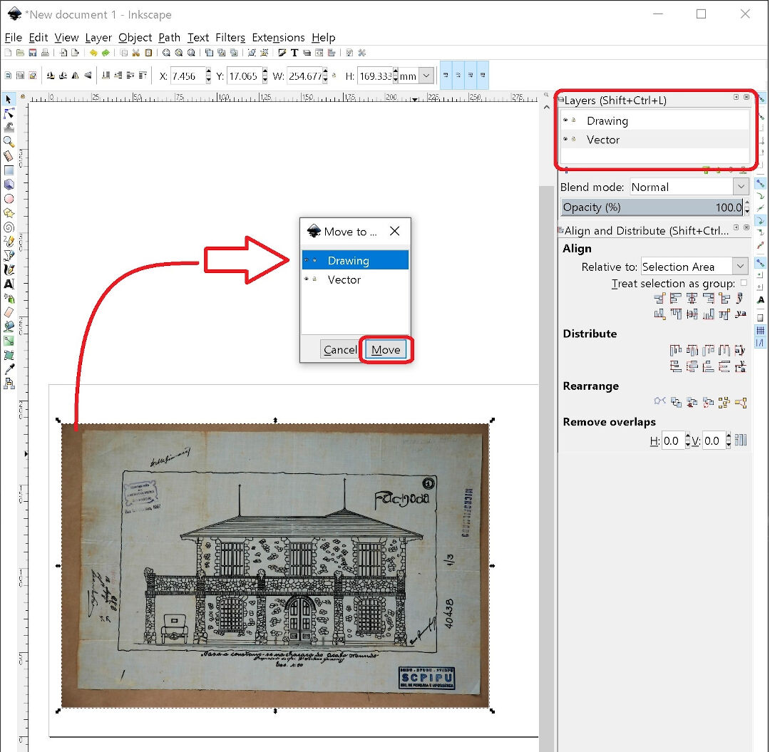
Now I turn off the original raster image by clicking on the eye symbol next to the vector name. That will allow me to only see the vector. Next, I will focus on the old car.
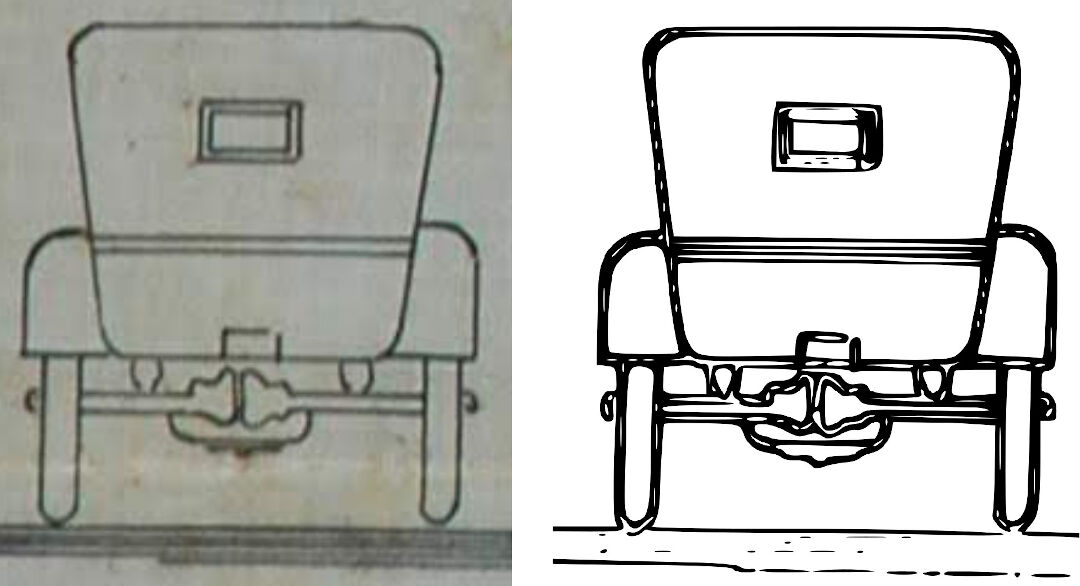
Here we can see the Raster image on the left and the vector image on the right side.
I tried to select only the car and then invert the selection, but that did not work; maybe it's too big a file. So I proceeded to select the vectors and delete them. This makes the image less heavy and the computer less slow.
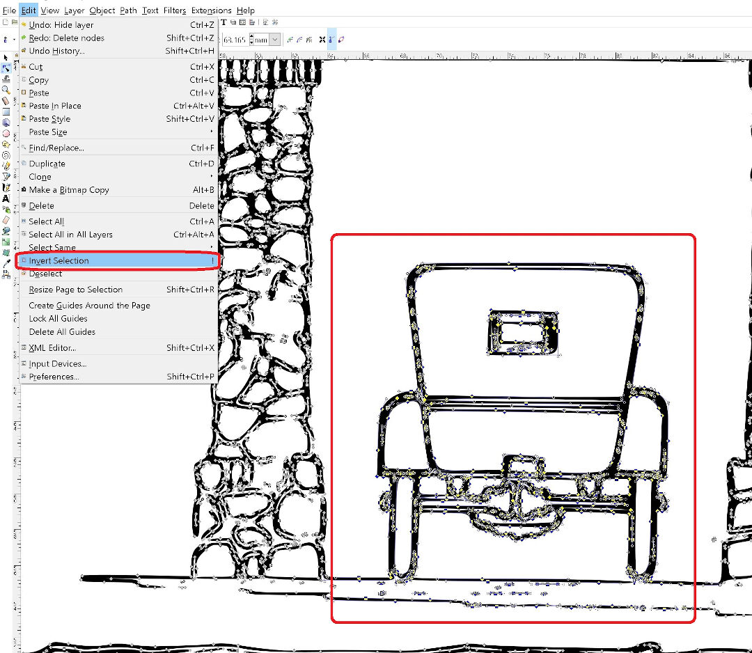
Here I show how I select the nodes and then delete them. In number 3, I show where I will focus next.
Here I show the node editing. By moving the center of the node or the lever, I can change the shape of the image.
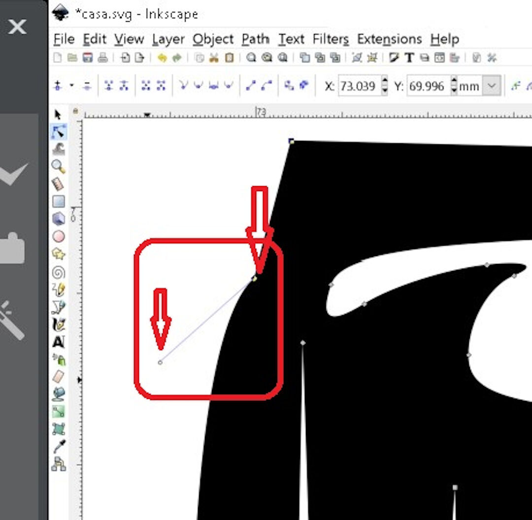
That manipulation allowed me to extract the car from the raster image. Now I can use the laser cutter or another digital manufacturing machine to follow the path of the vector, but that's for another week.
Fusion 360
In my review of Fusion 360, I will go through the process of creating two solids. One will match the other, based on the grain contour of an oak door frame piece I need repairing.
- I started by taking a picture of the damage on the oak door frame I want to try fixing.
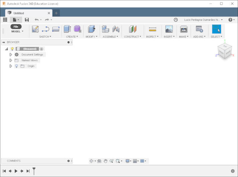
- When Fusion starts, the work area opens automatically, and one can just start designing.
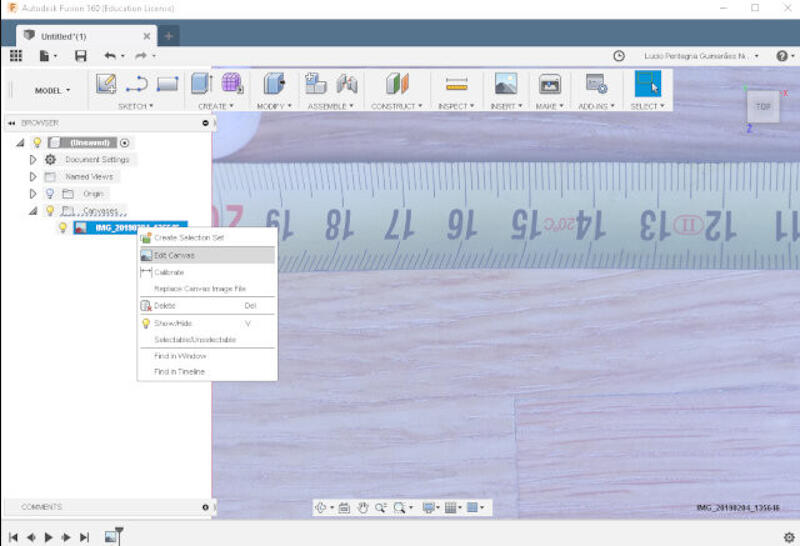
- The repair I am attempting is based on the grain geometry of the oak. For that reason, I will first insert the picture previously taken into the Fusion environment. The following steps are going to create a 2D sketch environment and let one insert a picture on it for future reverse engineering:
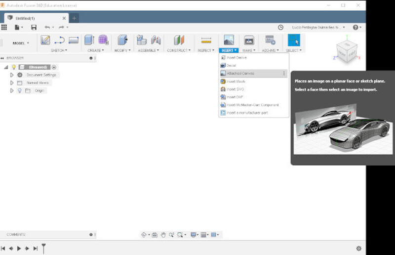
- Click on Insert
- then click on Attached Canvas
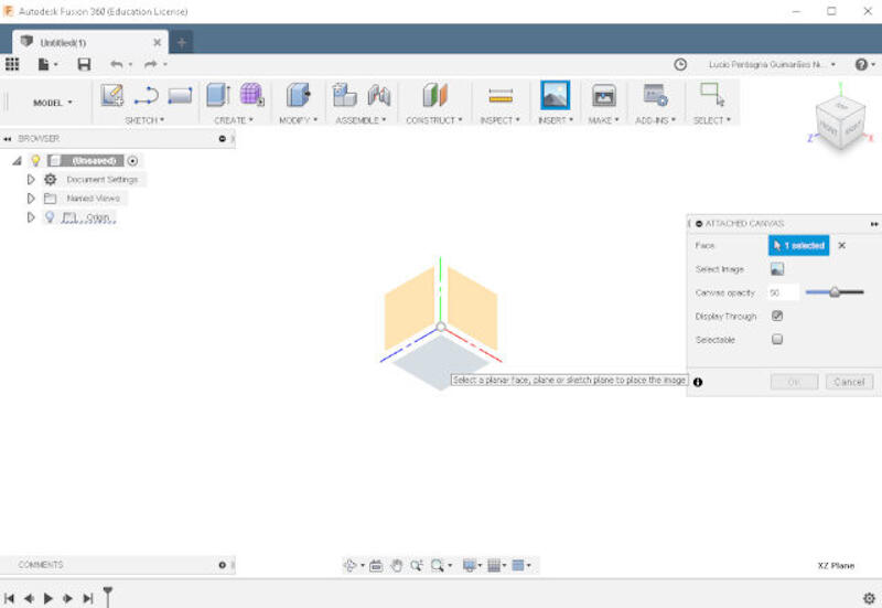
- Now one needs to select a plane. The image or canvas, as Fusion calls it, will be inserted next on that plane.
- Directly click on the desired plane. In case one has previously created a solid, a face can be selected as well.
- With the plane selected, it's time to find the image.
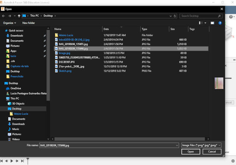
- In the opened dialog, click on Select Image.
- A file explorer will be opened, allowing you to find the desired file, select it.
- Press Open.
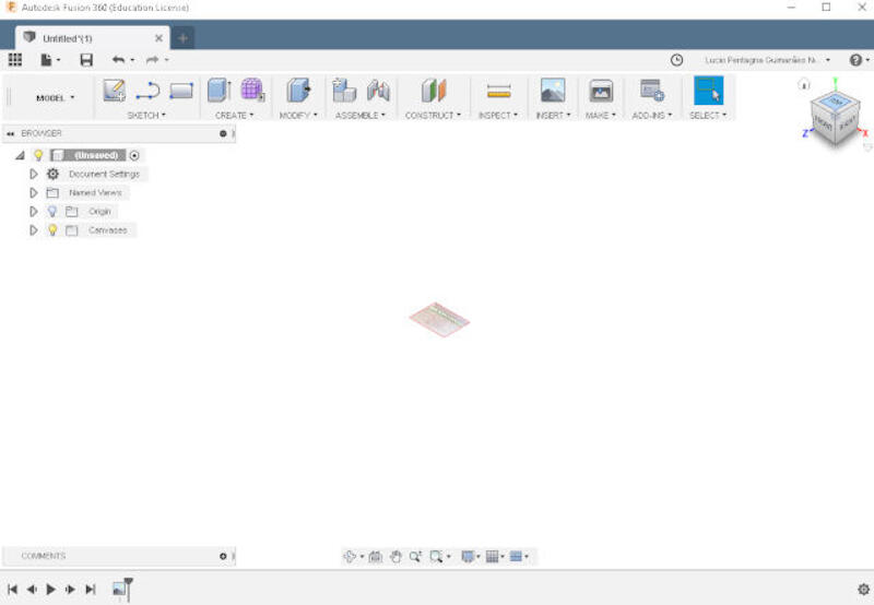
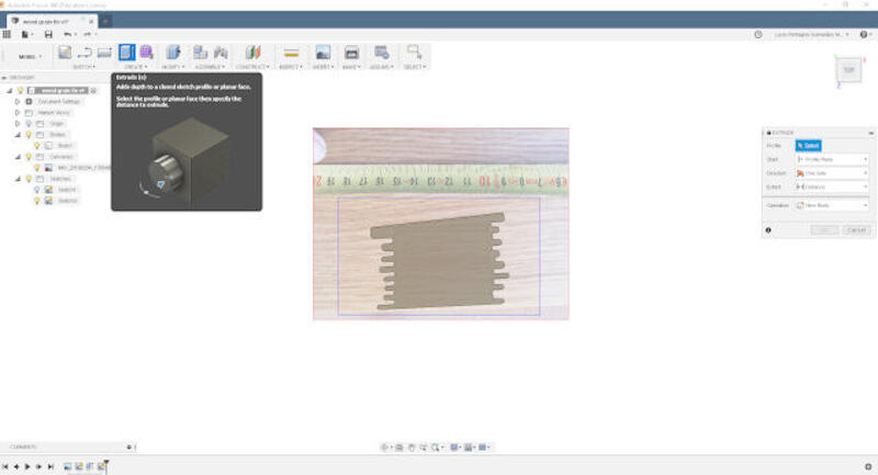
- This frame shows the image inserted on the XY plane.
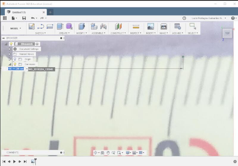
- Now it's time to scale the image.
- Click on Calibrate.
- Now, using the ruler as a reference and as accurately as possible, select two points and insert the known measure.
- Click on the first point.
- Click on the second point.
- Using the ruler in the photo as a guide, type the known measurement.
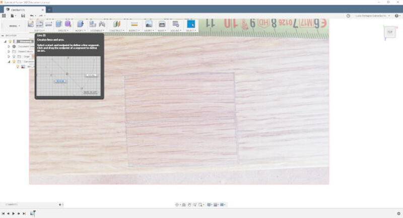
- Now, with the image aligned and scaled, it's time to sketch a 2D design.
- Click on Sketch.
- Click on the image.
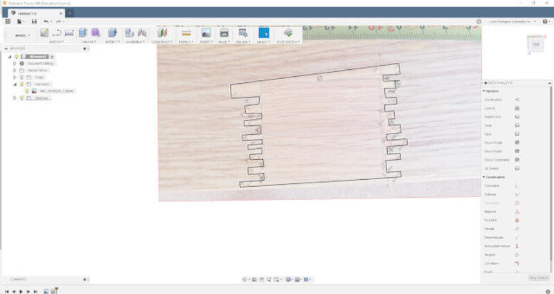
- Following the image grains, draw a pattern.
- Basically, following the pattern of the grain, I draw lines to form a geometry.
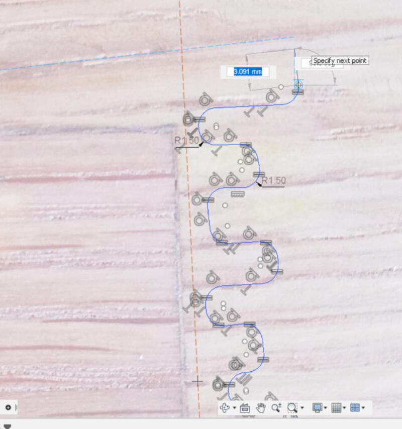
- That's the Geometry with sharp corners.
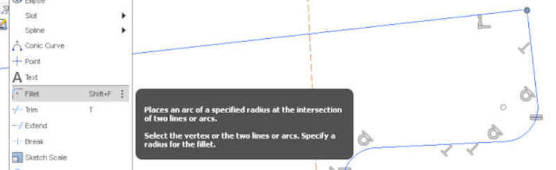
- In order to remove the sharp corners, as they won't be milled, one can use the Fillet tool.
- In the Sketch drop-down menu, select Fillet.
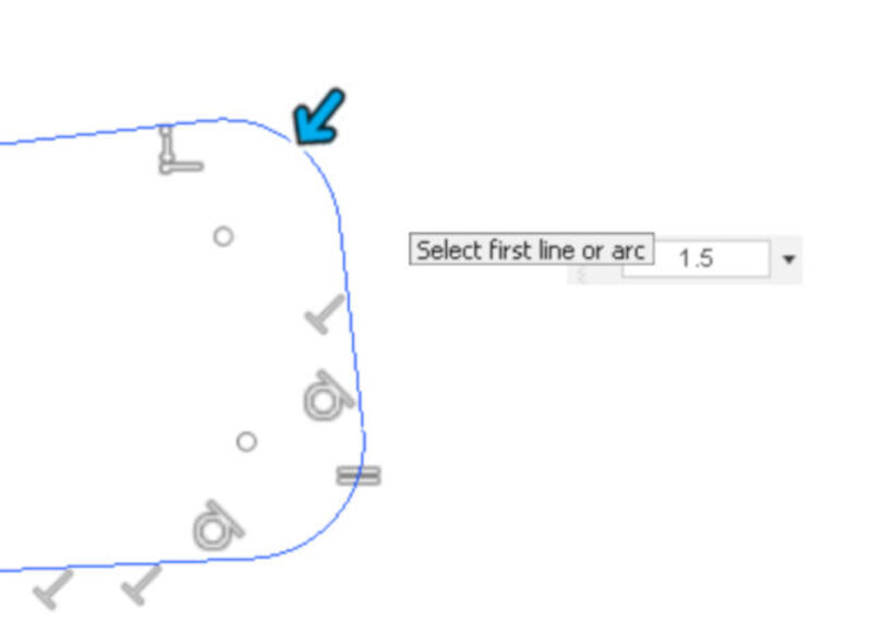
- Select the corners to be filleted.
- Add a dimension. In my case, I typed 1.5mm, as this is the radius of the tool I will use to mill the wood damage.
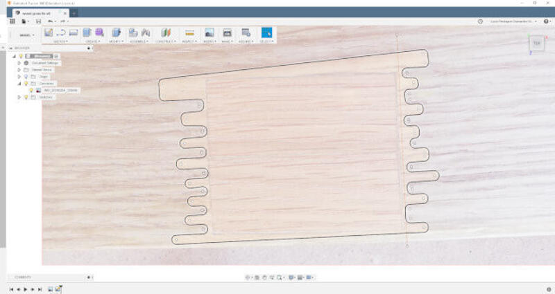
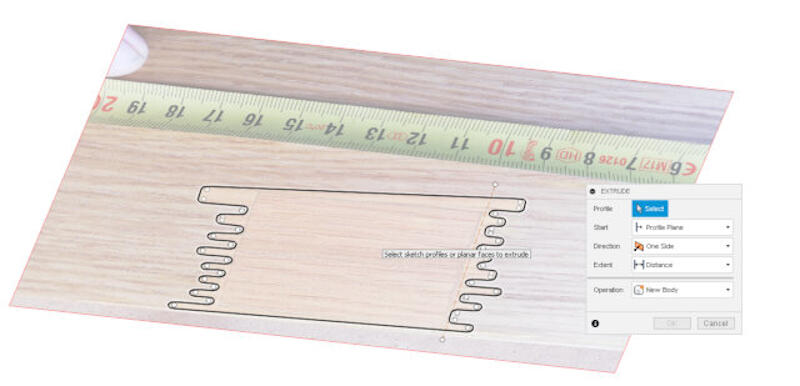
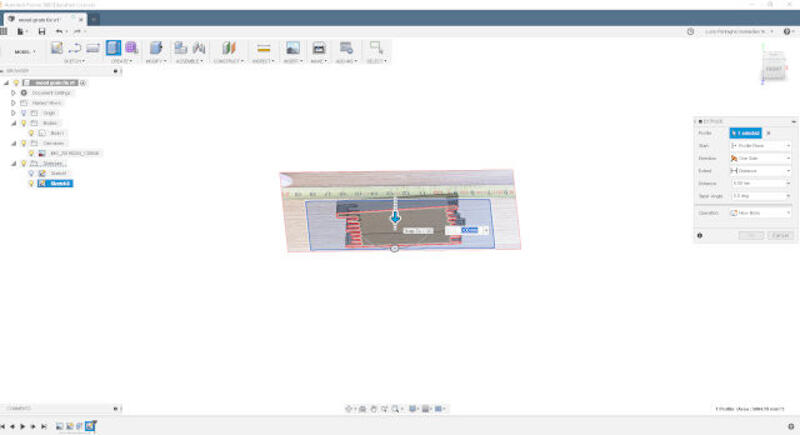
- The final 2D sketch is done and ready for virtual extrusion.
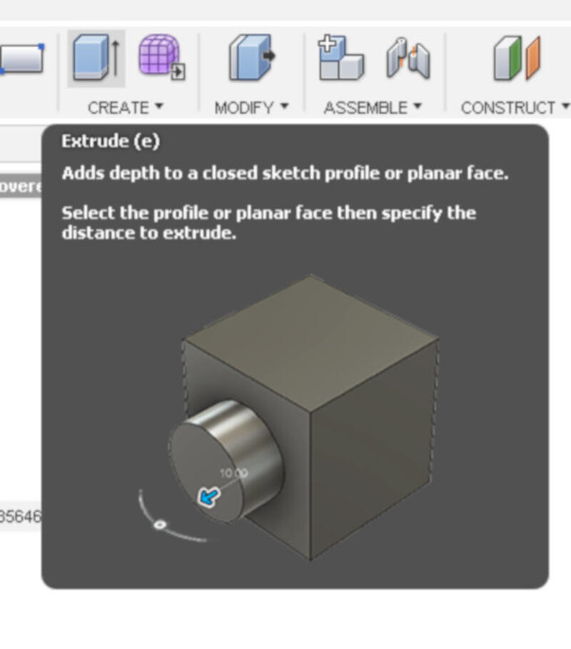
- The process of virtual extrusion, in summary, is the same as creating a solid 3D object from a 2D sketch:
- Click on the Extrude icon on top of Create.
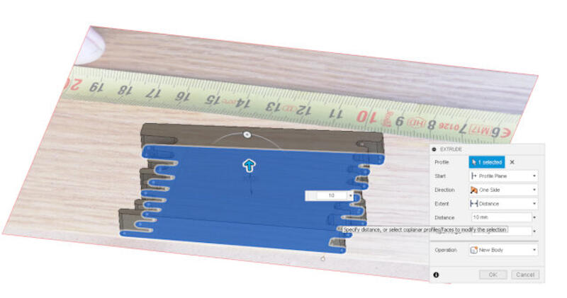
- Select the 2D sketch.
- Add a dimension.
- Based on the solid (positive), one is ready to make the negative part.
- In my case, I wanted to have a negative and a positive of the shape so I can mill the pocket and the repair piece. So the next steps:
- Select the underside.
- Click on Create Sketch.
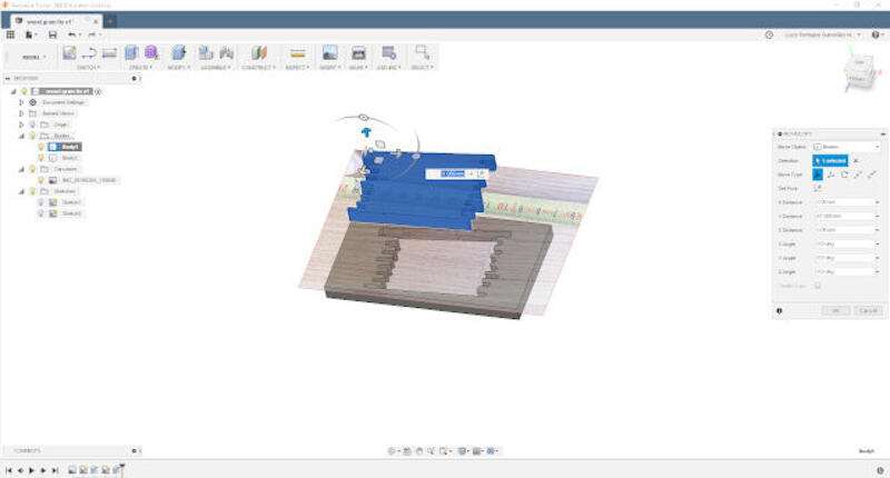
- With the new sketch created, I drew a square around it in preparation for the next step.
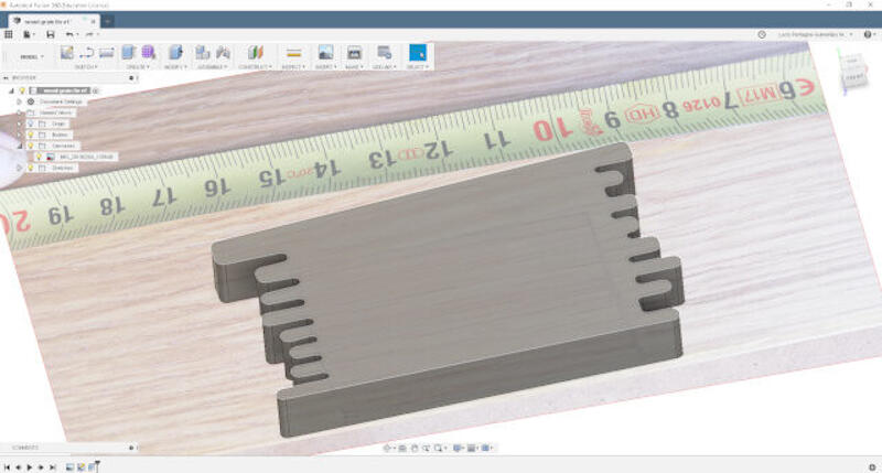
- Selecting the new sketch and following the same steps as when making the last solid, I could extrude the base for milling the pocket.
- That's how both parts look like.
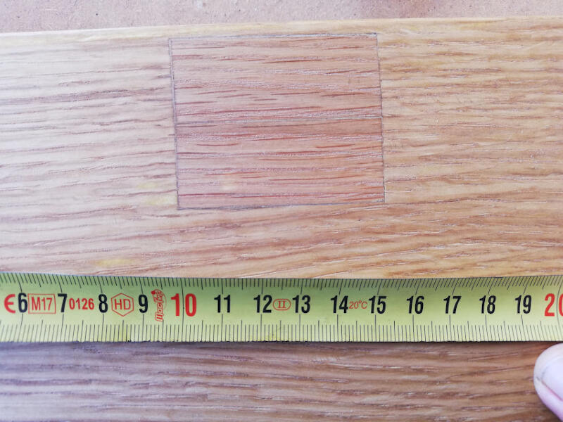 The ruler in the photo will be used in the following steps.


The review of Solidworks 2019 and my Final Project.
Solidworks has been my software of choice for the last few years when it comes to mechanical design. I am very happy with it as it's powerful and allows quite complex assemblies while being intuitive enough for me to learn by using it.
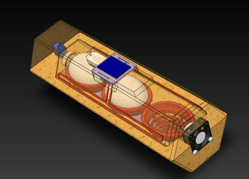 Image of my possible final project

- incubator Solidworks source files on Fabacademy Gitlab
- Egg
- Case (top)
- Case (bottom)
- Egg Crate
- Heat Element
- Water
- Fan Designed by Xgentec Jason at Grabcad
- Servo Motor Designed by Akshaya Simha at Grabcad
- Ball Bearing Designed by Hendricks at Grabcad
- Oled Display Designed by thmjpr at Grabcad
- Humidity Sensor Designed by Nonthanut Hoku at Grabcad
Design files of final project proposal
Designed Parts
Downloaded Parts
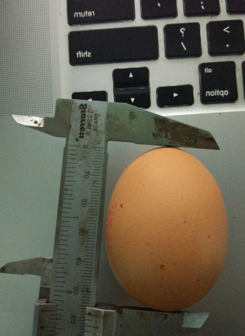
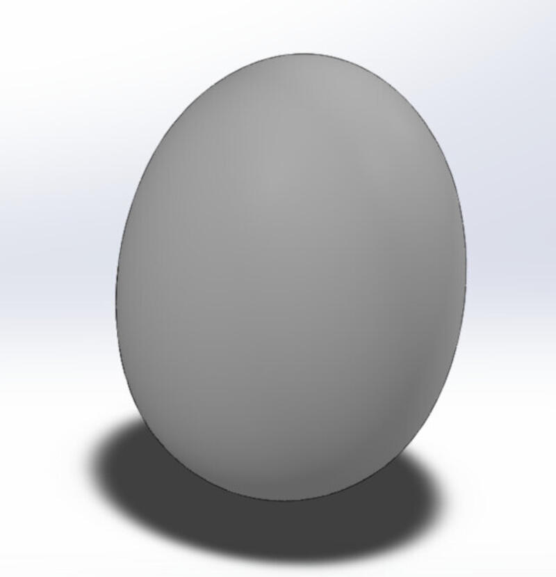
1. The egg (where it all starts)
- In order to design my final project, I started with designing an egg.
- I took a picture of a real egg with the caliper for reference later in Solidworks.
- To use the feature, start a new sketch, then in the menu go to: Tools > Sketch Tools > Sketch Picture.
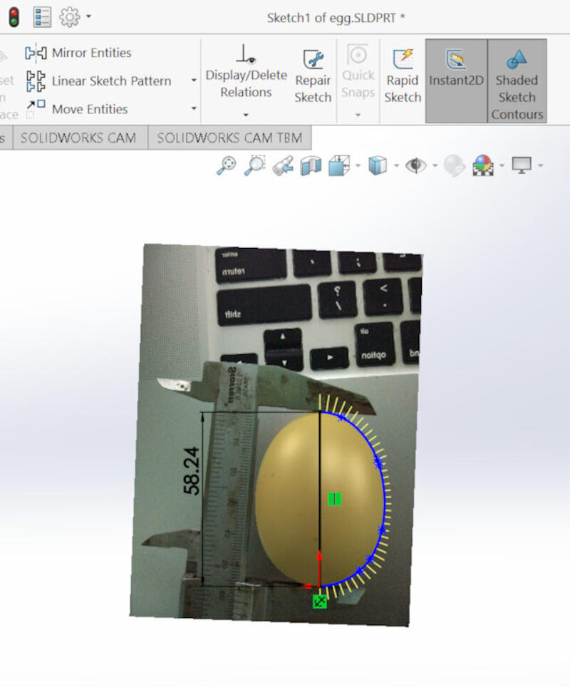
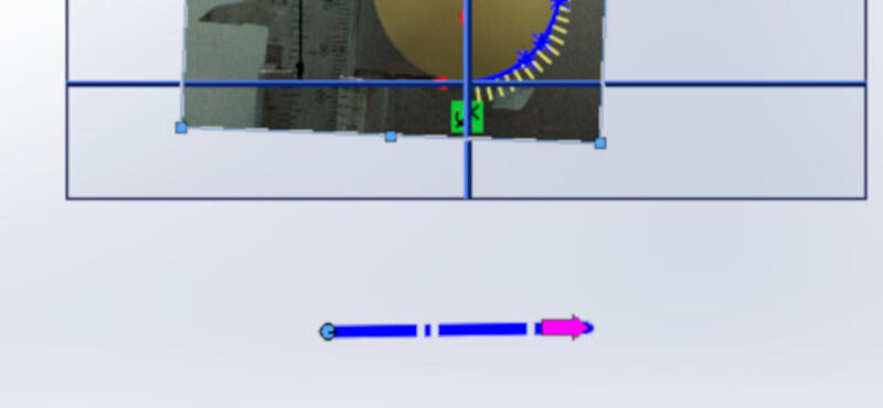
- After inserting the picture, scale it using the caliper reference as well as the blue ruler provided by Solidworks.
- With the picture calibrated to scale, it's time to sketch around. For this, I used the spline tool and closed the spline with a construction line.

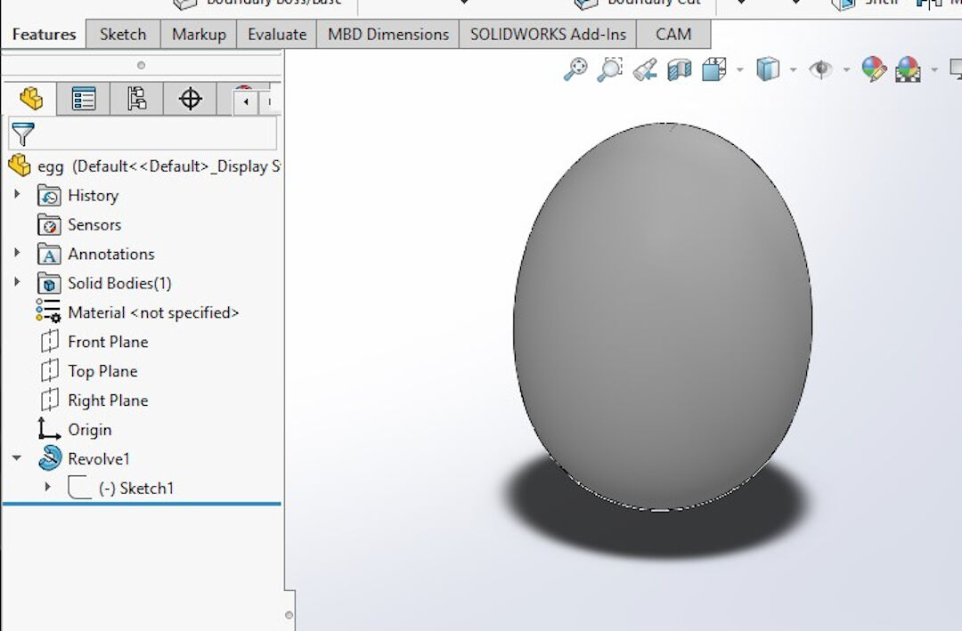
- Leave the Sketch and Click on Revolved Boss/Base.
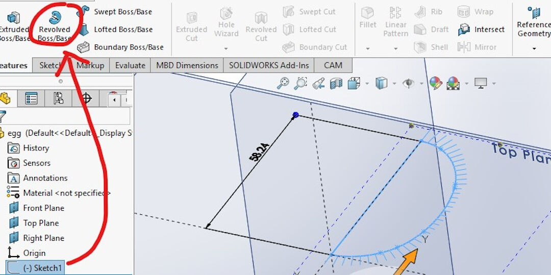
- If the axis of rotation is not selected automatically, select the line that is in the center of the future egg. Press the green check mark.

- Voila, the virtual egg is made!
3. Bottom Case
Because of the number of steps, I will only detail the most important ones, specifying the type of operation in the beginning and then some of the steps to accomplish it.
- I started by sketching two hexagons and extruding them.
- Converting a contour of another object in an assembly:
- With the fan already mated with the sides of the case, I selected the outside contour of the fan and converted it, creating a sketch.
- Next, I cut the space for the fan.
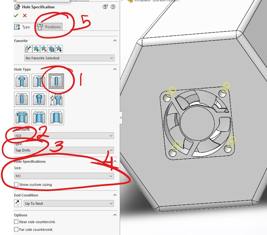
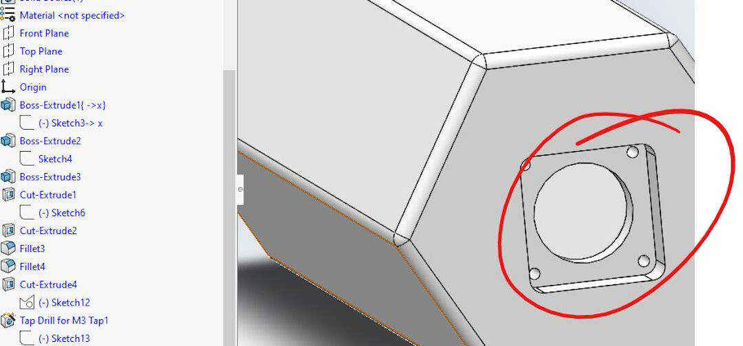
- Screw wizard
- In the type of Hole, I selected a simple hole as I will later tap the thread.
- In the standard, I selected ISO as it contains metric screws.
- In the type of drill, I selected tap drill as this will give the right clearance to use a manual tap to open a thread later.
- Here I selected the size of the screw M3.
- Next, I clicked on position to determine where the holes will be located.
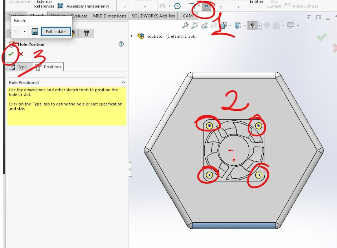
- Position of screw holes:
- The point sketch is normally selected already unless you had to create construction lines or other operations.
- Next, I centered each point on the locations where the fan will receive the screws. Lastly, confirm and close the operation, and the result will be holes created in the surface previously selected.
- Here is the result of the previous operation, the holes in place.
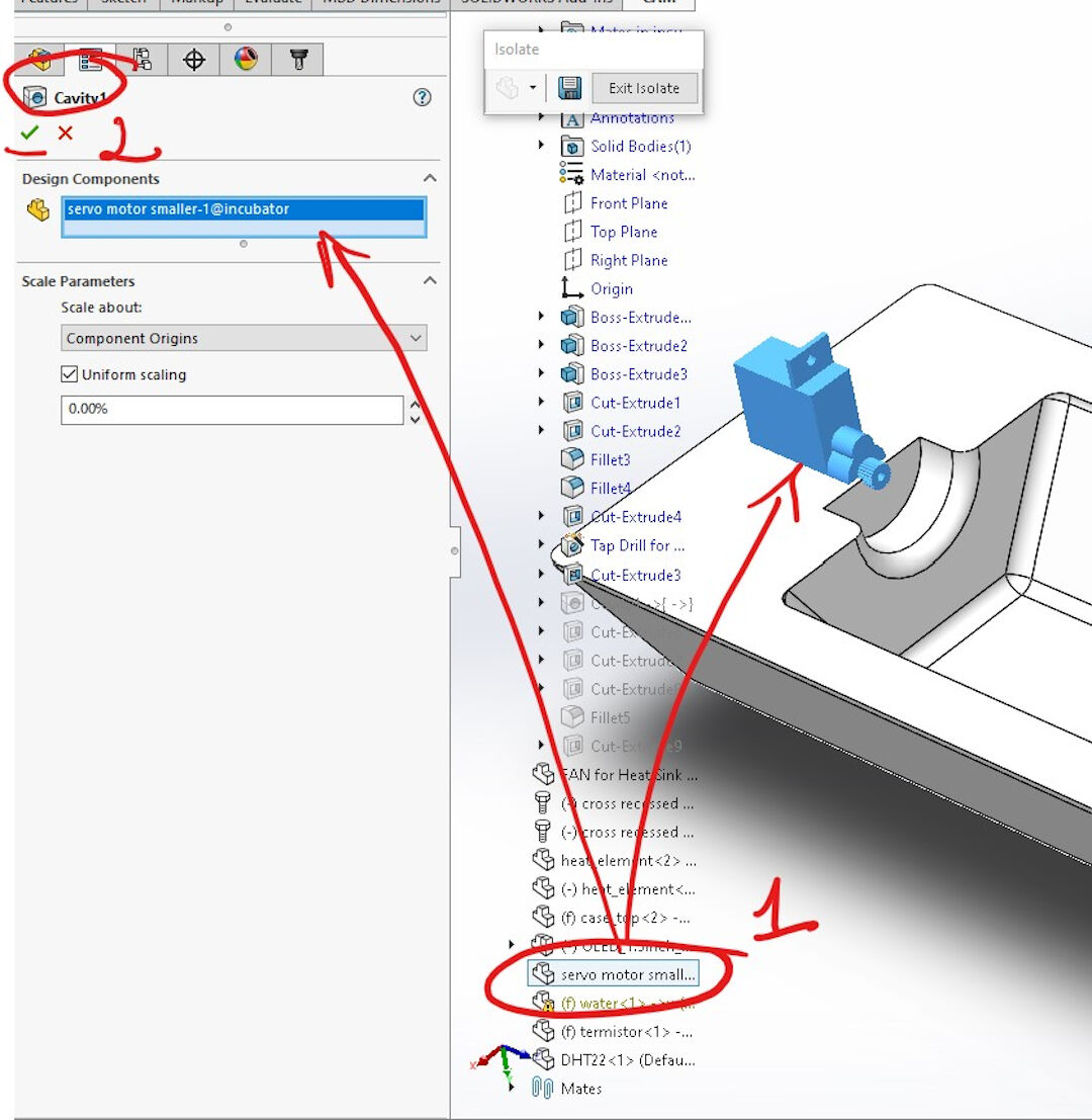
- Cavity, this operation is useful as it will save time designing many features that, in this example, will be simply inherited from the selected object or body:
- Simply start by either searching in the search menu for "cavity" or finding it on the "insert" "features" menu. After the feature is initiated, I selected the part I wanted to inherit the features, creating a kind of negative stamp in my part.
- Then simply confirm the operation.
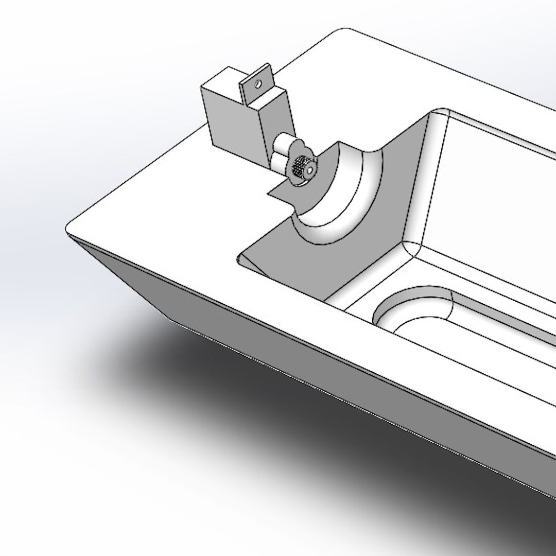
- Here you see the part with the cavity already created.
- Here you see the cavity.


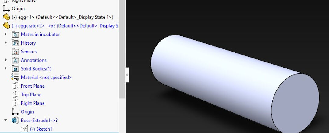
4. The crate
- The crate was a bit complex to create.
- I started by extruding a cylinder.
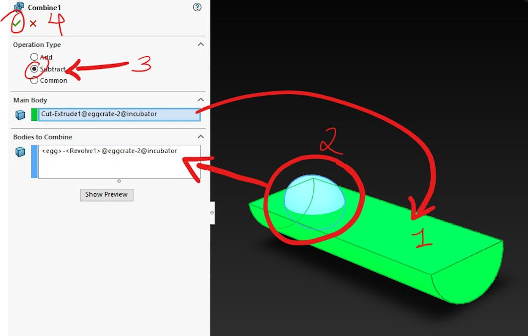
- Next, I cut it in half by sketching a half circle on one of its faces.
- This time, I used the combine feature instead of cavity.
- The main body should be already selected by default.
- Next, I selected the part I wanted to combine.
- In order to create a footprint, I selected the operation subtract.
- Lastly, select the confirmation check mark to finish the combine feature.
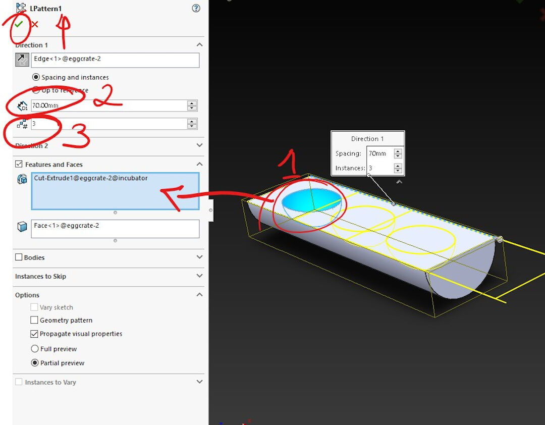
- Linear Pattern is a feature used to replicate in various directions a feature, so it saves time instead of designing the pattern feature again and again:
- I started by selecting the pattern.
- Then I selected the distance between the patterns.
- Then I specified it to replicate it three times.
- Next, I confirm.
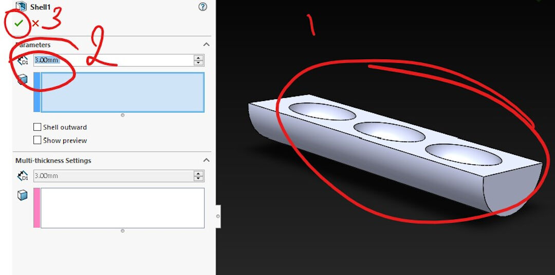
- Here I used the shell feature as I wanted to keep the contours, but I wanted the interior to become empty. This was done simply by specifying the thickness, in my case, 3mm, and I did not have to select the body as it was already selected before initiating the feature.
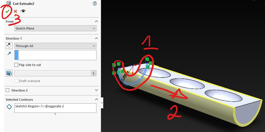
- Now, in order to expose the previous feature, I cut the lower shell by sketching around the lower shell of the body.
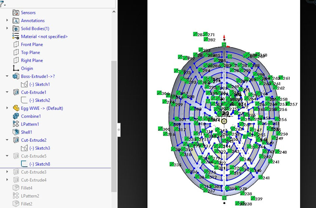
- This was a simple cut feature with a complex sketch. The sketch was created by offsetting inwards the outer contour, drawing lines towards the center, and lastly trimming all the lines in order to form closed perimeters that were used to cut the shape.
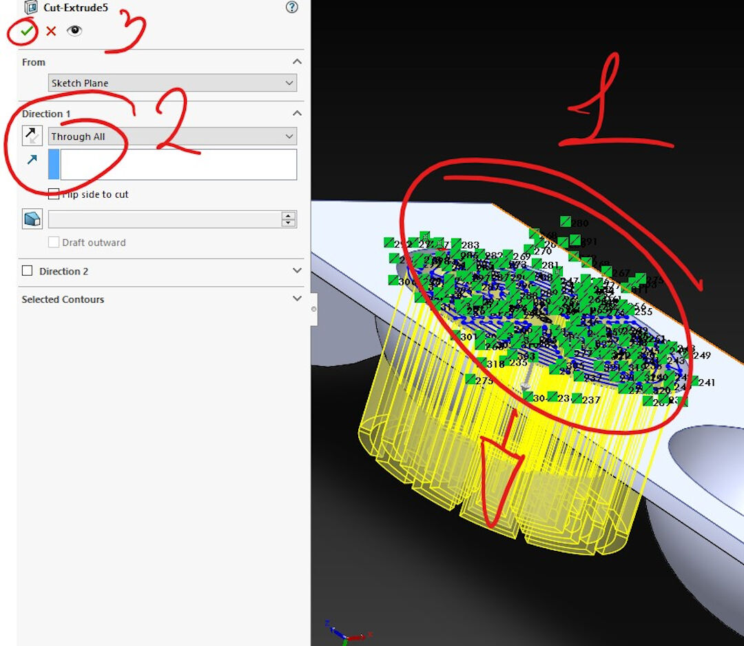
- The cut feature is trivial and was done simply by selecting the previous sketch and cutting it through all.
- This was again a linear pattern done in the same manner as the previous one.
- I then extruded cut the rest of the wall off the once shell of the half cylinder.
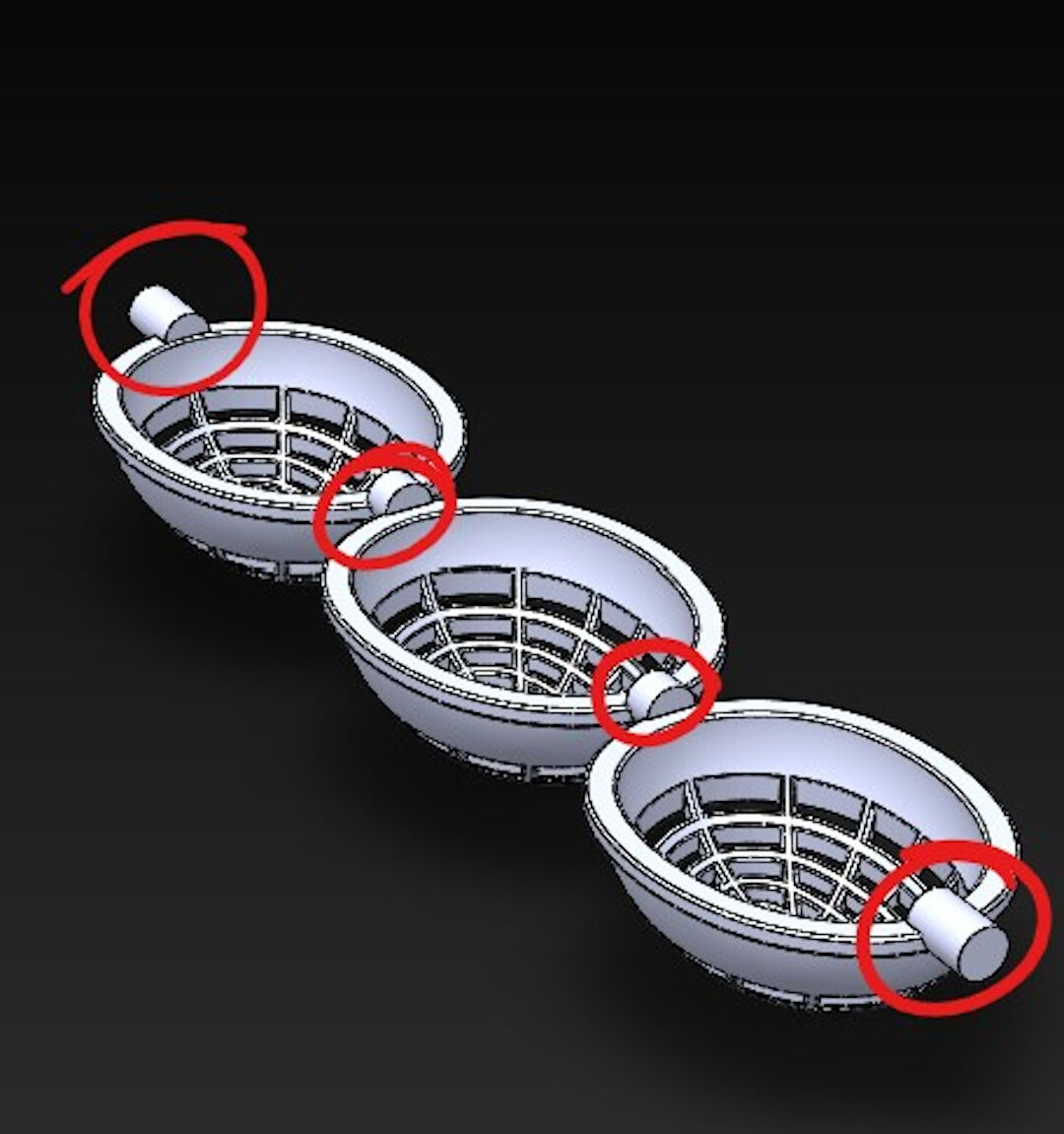
- Lastly, I extruded cylinders in between each basket to work as a shaft.
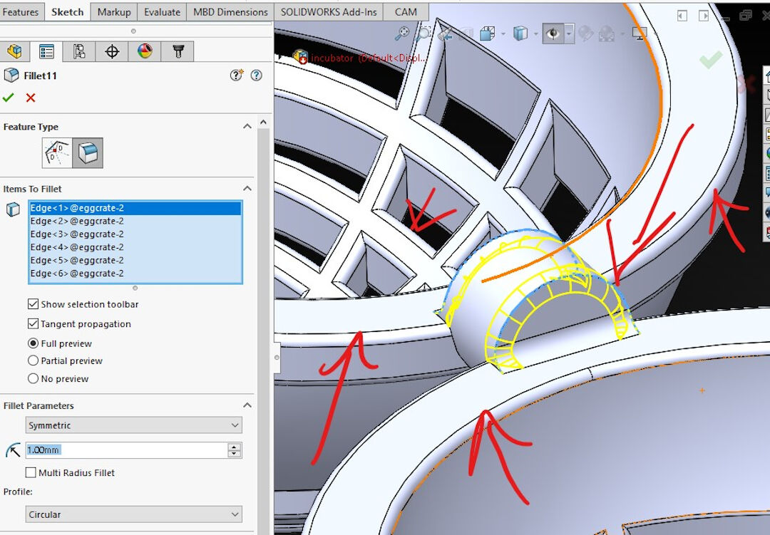
- Fillet was used everywhere in this part. Here I exemplify the shaft being reinforced with the fillet operation.
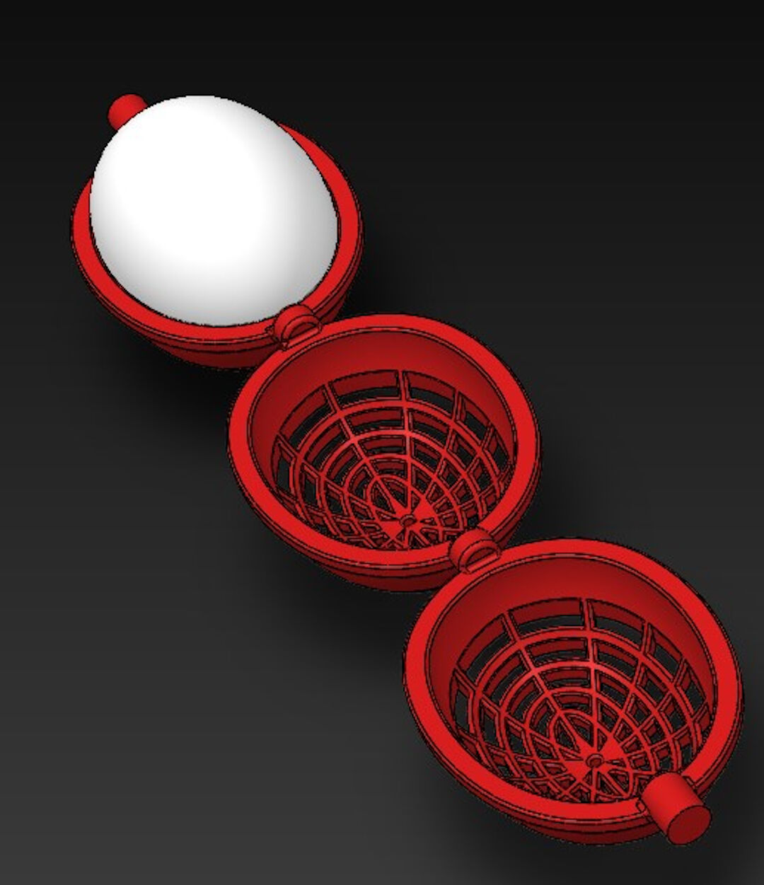
- The final result of the crate.


Extra Credits - Milling stuff
Remember the Fusion360 review? Well, I decided to post photos only of the final result with the mill. I know CNC milling is not this week, but I couldn't resist. So not a proper documentation, just some hero photos of the final result.
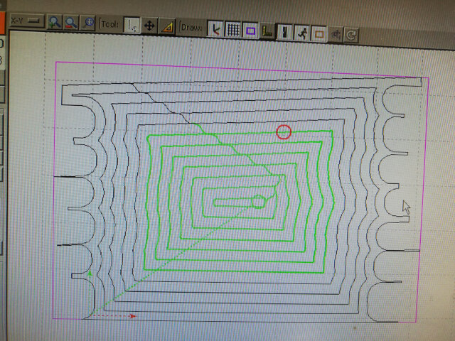
- This tool-path was made with Fusion 360, and it is rendered here in the software BCNC. BCNC is a GRBL controller I use with our fablab-made CNC.
- The CNC mill's spindle here is displayed creating a pocket in the wooden door frame.

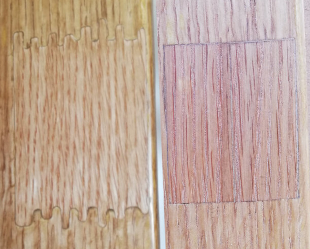
- Both pieces here right before assembly.

- The pieces did not fit perfectly. We had to file a little. So this shows we will need to do some calibration of the CNC mill in the following weeks. Also, I don't like that the veneer was raised from the plywood where the CNC went against the grain.

- Here the pieces are glued together but not yet stained with linseed oil.

- After and Before photo.
Solidworks has been my choice of 3D design software for some time. I learned to use it with videos and tutorials online.
| Solidworks | Fusion360 | Inkscape | |
|---|---|---|---|
| 3D Design |
yes | yes |
no |
| 2D Design | yes | yes | yes |
| CAM | yes | yes | 2D only yes with plugin |
| Parametric | yes | yes | yes |
| Run locally | yes | cloud-based | yes |
| Price | $$$$ | $ | free |
| Windows | yes | yes | yes |
| MacOS | no | yes | yes |
| Assembly-driven | yes | no | no |
| Large assemblies | yes | has trouble | no |
| Simulation solutions | depends on package | beginner plug-ins | no |
| Mesh modeling | not intuitive | yes | no |