3D Scanning and Printing
Group Assignment
Go to the group assignment page
Individual assignment
- Test the design rules for your printer(s) (group project)
- Design and 3D print an object (small, few cm) that could not be made subtractively
- 3D scan an object (and optionally print it)
Learning outcomes:
- Identify the advantages and limitations of 3D printing and scanning technology
- Apply design methods and production processes to show your understanding.
Have you:
- Described what you learned by testing the 3D printers
- Shown how you designed and made your object and explained why it could not be made subtractively
- Scanned an object
- Outlined problems and how you fixed them
- Included your design files and ‘hero shot’ photos of the scan and the final object
Week workflow
Weekly assignment: Test Printer → Design an object → Print object → Scan object → Print scanned object (optional)
Tools used
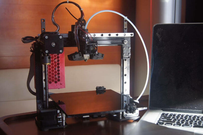
- Delta 3D Printer
- Mini 3D Printer
- Caliper
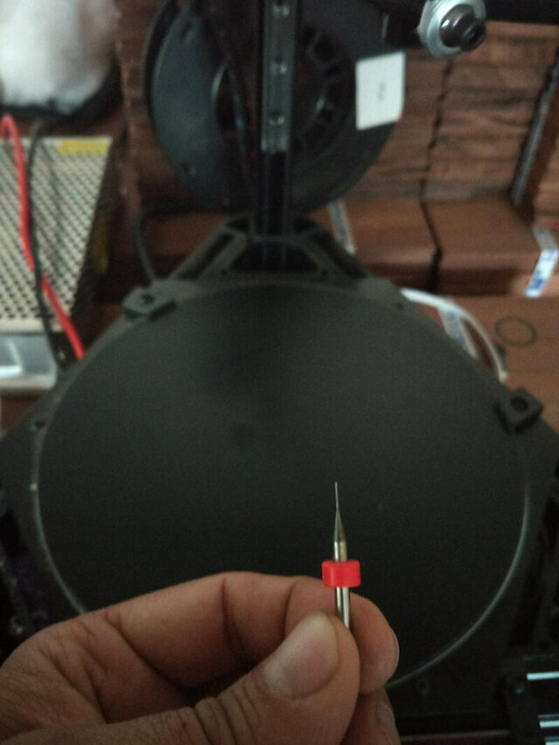
- 0.4 mm needle
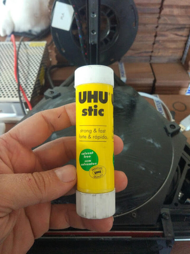
- Uhu glue
Software Used
Files Generated/used
- Test's stl file: 3D Printer test model from thingiverse
- G-code file: all week's generated G-code from STL files and scanned stone model
- Solid Works file: Project page of the 3D model for a wire organizer used on a CNC I built
- Chain's stl file: Generated stl file from the Solidworks archive
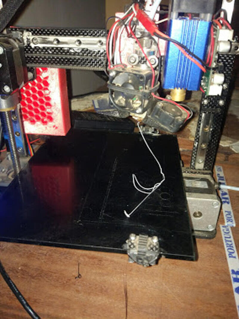
- Printers preparation
- To start the test, I prepared the printers by cleaning the nozzles and spreading new glue onto the platforms.
- I tested the extrusion on both printers, and it looked good.
- The limits of our printers
- I started this week's assignment by looking for a test pattern on the website
Thingiverse
. Simply by using its search engine with the keywords,
test 3d print
it showed various results with the purpose of testing the printers.
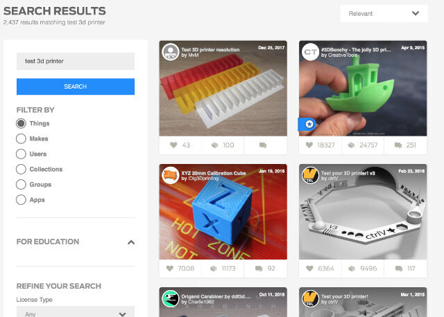
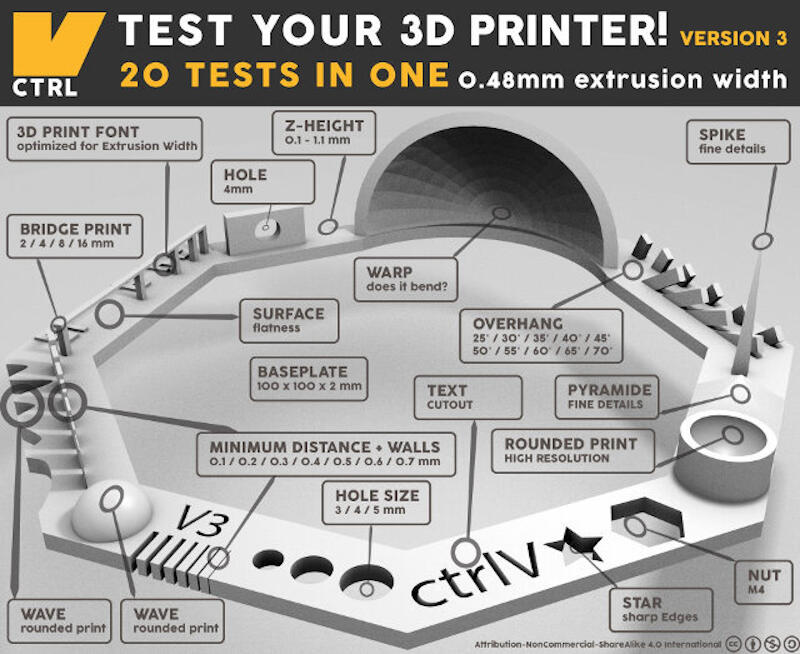
- I selected one of the designs, which tests different capabilities of the printers.
- Nut, Size M4 Nut should fit perfectly
- Wave, rounded print
- Star, Sharp Edges
- Name, Complex Shapes
- Holes, Size 3, 4, 5 mm
- minimal Distance: 0.1, 0.2, 0.3, 0.4, 0.5, 0.6, 0.7 mm
- Z height: 0.1, 0.2, 0.3, 0.4, 0.5, 0.6, 0.7, 0.8, 0.9, 1.0, 1.1 mm
- Wall Thickness: 0.1, 0.2, 0.3, 0.4, 0.5, 0.6, 0.7 mm
- Bridge Print: 2, 4, 8, 16 mm
- Sphere, Rounded Print 4.8mm height
- Sphere Mix, 7 mm height
- Pyramid 7 mm height
- Overhang: 25, 30, 35, 40, 45, 50, 55, 60, 65, 70°
- Warp, does it bend?
- 3D Print Font, optimized for 3D printing
- Surface, Flatness
- Size, 100 x 100mm x 23.83 (10mm width)
- Spike, minimum Layer Time, 21 mm height from Bottom (include Baseplate)
- Hole in Wall, 4 mm diameter, check for proper print
- Raft Test, raft should be just under the model
- Retract Travel, check retract settings for longer travel
- In Repetier Host, I loaded the STL file and sliced it for each printer, naming the G-code with the printer designation in front.
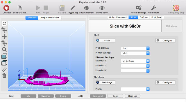
- 3D printers are far from being plug-and-play devices. There is a lot of adjusting, and some of it seems like magic. I will highlight the most important points to consider in the settings of the Slic3r software, which works in conjunction with Repetier.
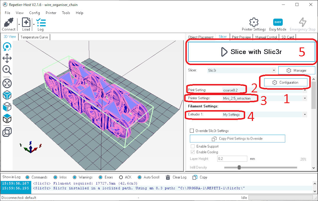
- Still on Repetier in the "Slicer" tab the software presents us with several options of preset configuration. The first is the slicer software itself. On the drop-down menu, it is possible to choose from Slic3r, Cura, or older software that nobody uses...
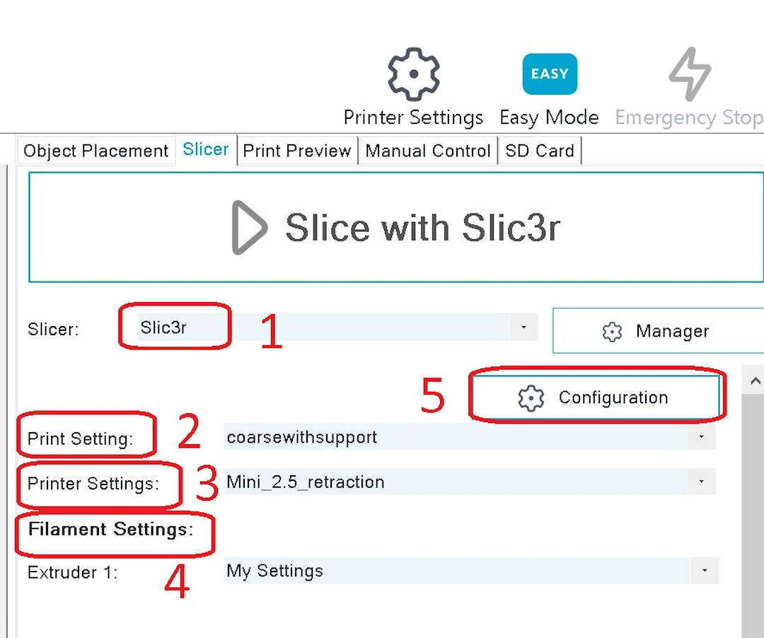
- In Print settings, we have characteristics of the particular model to print. My current choice is "coarsewithsupport"; later, I will discuss how I chose the settings that make up the presets presented.
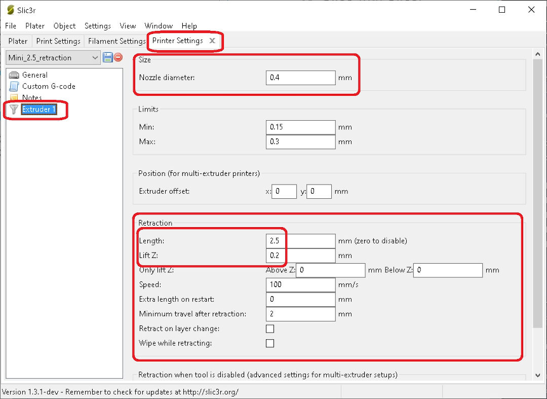
- Then we have "Printer Settings". Normally, settings related to a specific printer (machine) go here. In my presets, I have the different printers of the lab: one is a Cartesian printer, "Mini_2.5_retraction", and another (not shown) is a delta printer.
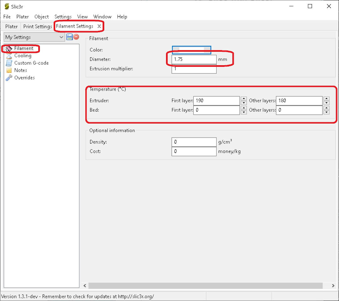
- Here, in "Filament Settings", are the many filaments one can have, each with different settings like color, temperature, or thickness.
- In this item, we will dive deeper into the settings and set up the presets displayed before.
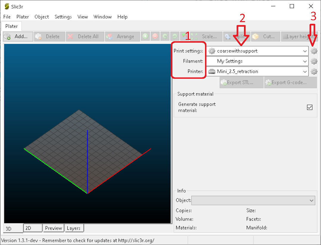
- As Slic3r presents in the first column, we have the classes: Print settings, Filament, and Printer.
- Then, in the second column, we have drop-down menus to choose each preset that the user wishes to customize.
- In the third column, we see a gear-shaped icon, a typical icon for configuration. Let's click on it to open each class and see its inner workings.
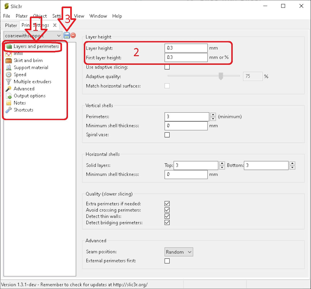
- Let's examine it sub-class by sub-class, starting with Layers and Perimeters.
- In this area, we can see Layer height. This is an important setting that should not go beyond the nozzle diameter size. If you are in a hurry and don't care about the appearance, go high. I have chosen 0.3 mm for a rough feeling. The layers will be noticeable, and slopes will look like stairs. If you need a detailed result, go low. The limits of how low this can go are near infinite, but because time is limited, I suggest not going lower than 0.1 mm. A lower number means more layers, and it will be smooth as peach skin.
- After each tweak, click on this strange blue square shape that reminds me of past times before all this excess of information and the echo chambers, before this true limitless universe of terabytes around us. It's called a floppy disk. If you don't click, believe me, you will regret it as nothing will be saved, but fear not, Slic3r won't let you do that without a warning.
- Next, I took the G-code I had saved on the SD card, placed it in the 3D printers, and started the print.
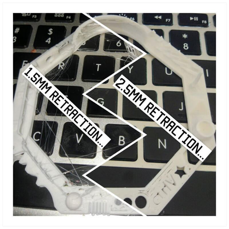
- The prints were not bad, but there was a lot of oozing (spider webs). So, I increased the retraction by .5 mm and then by 1 mm; the improvements were very noticeable in both printers.
- The results
- Designing and printing an object
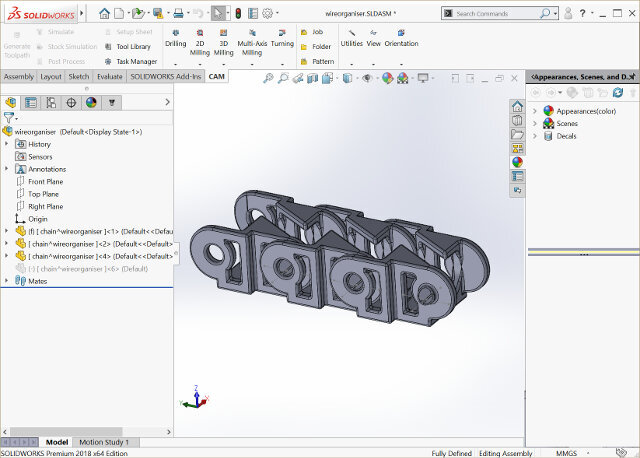
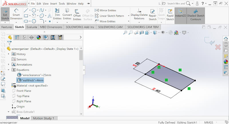
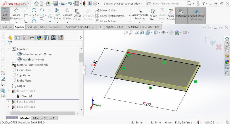
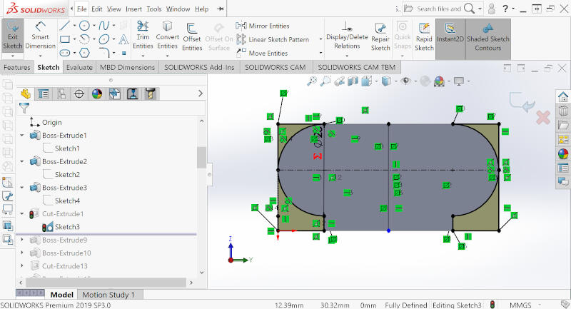
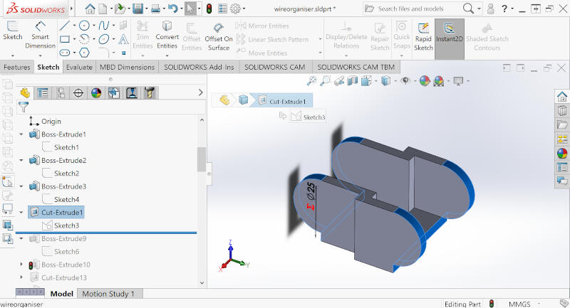
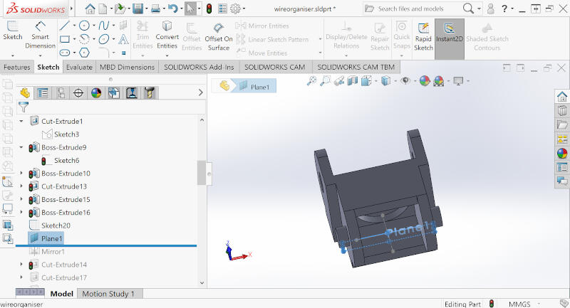
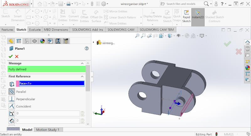
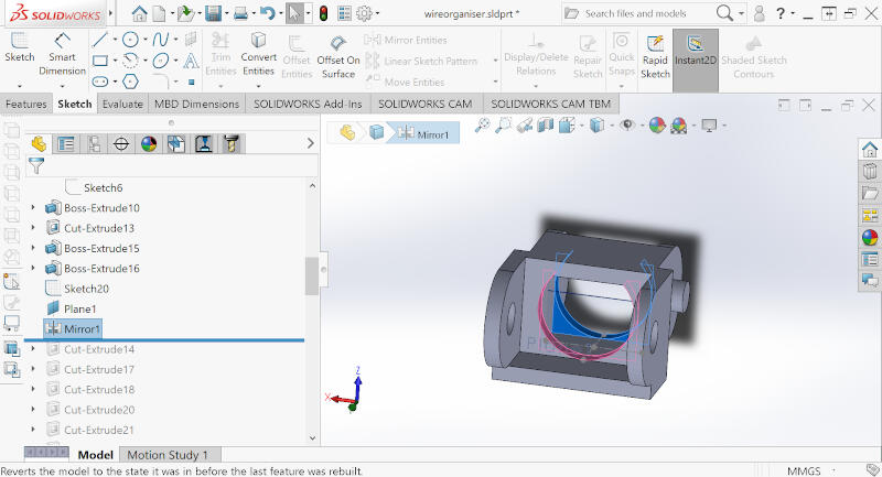
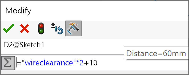
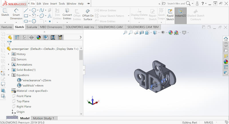
- I decided to create a necessary part for my final project: a wire organizer that, when connected together, works as a chain.
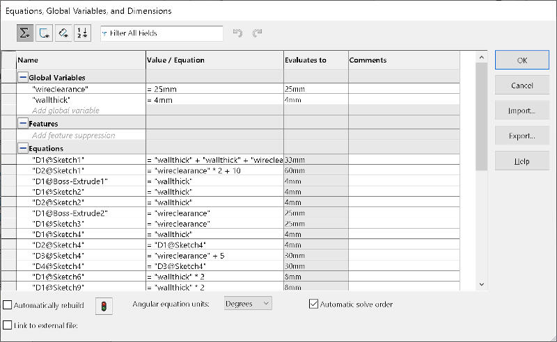
- The design is parametric, so I can easily change the size as needed.
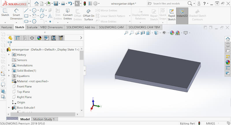
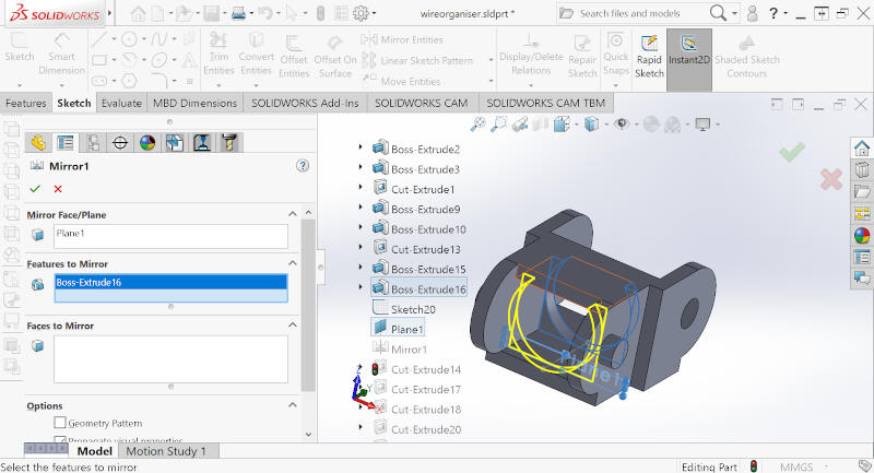
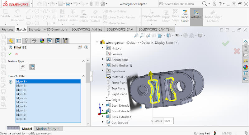
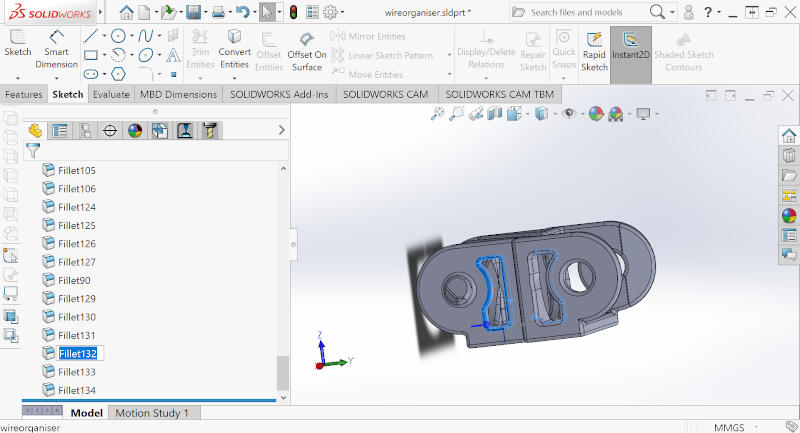
- The steps to design
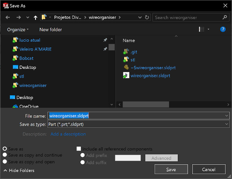
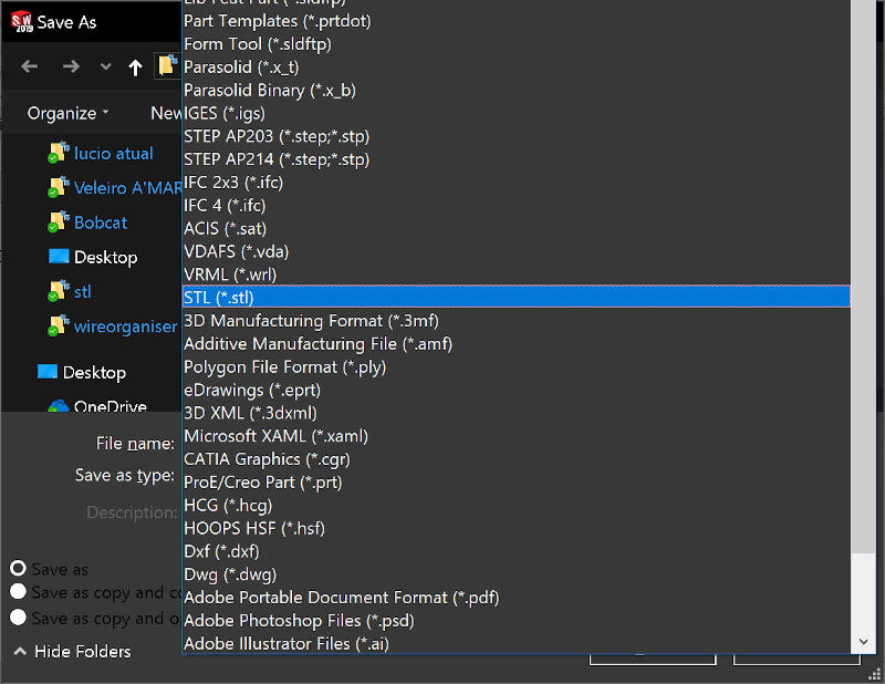
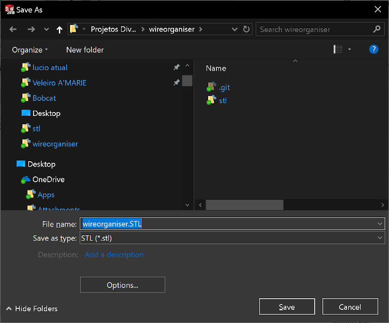
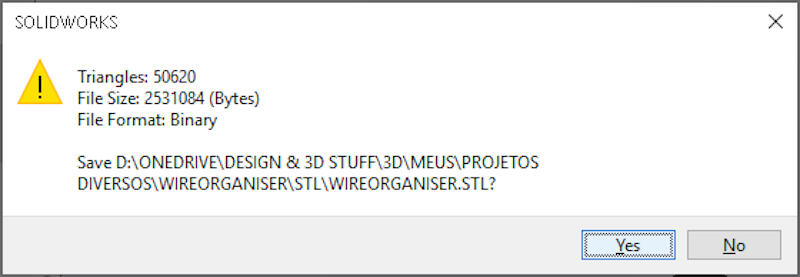
- As I finished the SolidWorks model, I then exported the file as STL.
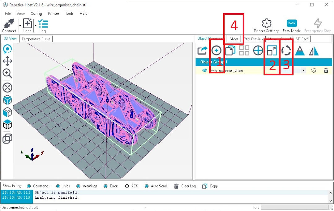
- Add the STL file.
- scale if needed
- rotate if needed
- click on slicer to get to settings and start slicing
- In Configuration, you can set particular characteristics of the slicing operation. Attached is the config bundle for our printers.
- With the preset loaded, here you choose print settings.
- Here, you can select the machine model.
- Here are the filament settings.
- Finally, click on "Slice with Slic3r".
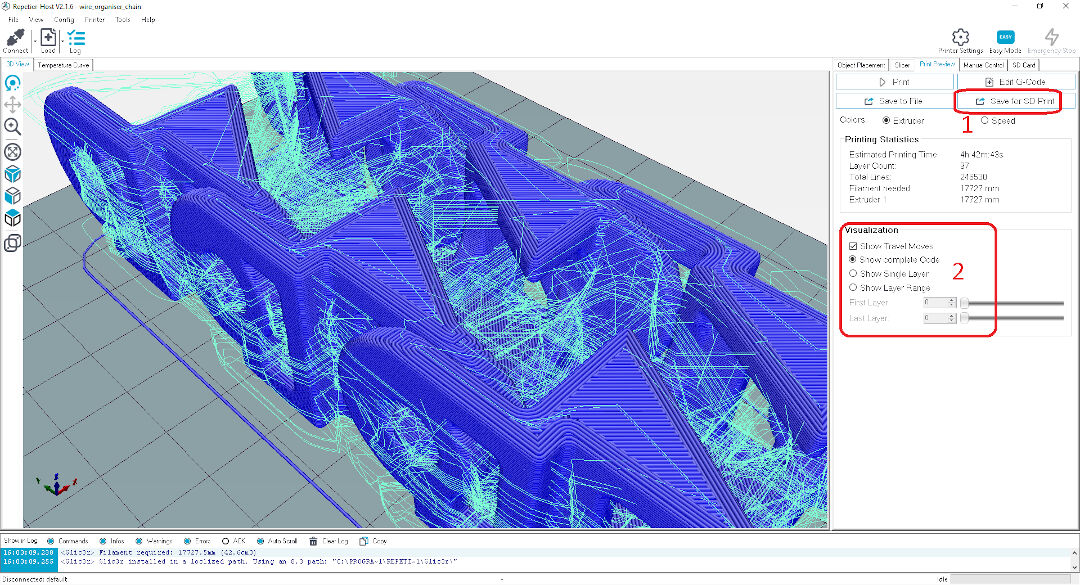
- Click on save to SD card to have your G-code saved to the media you will insert into a 3D printer.
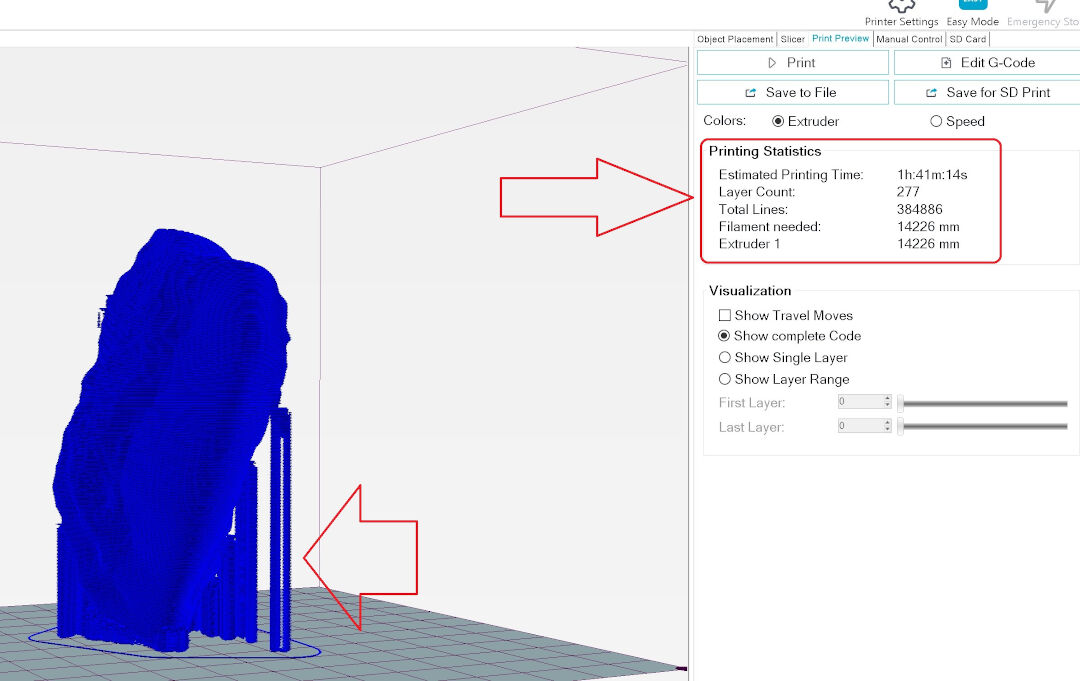
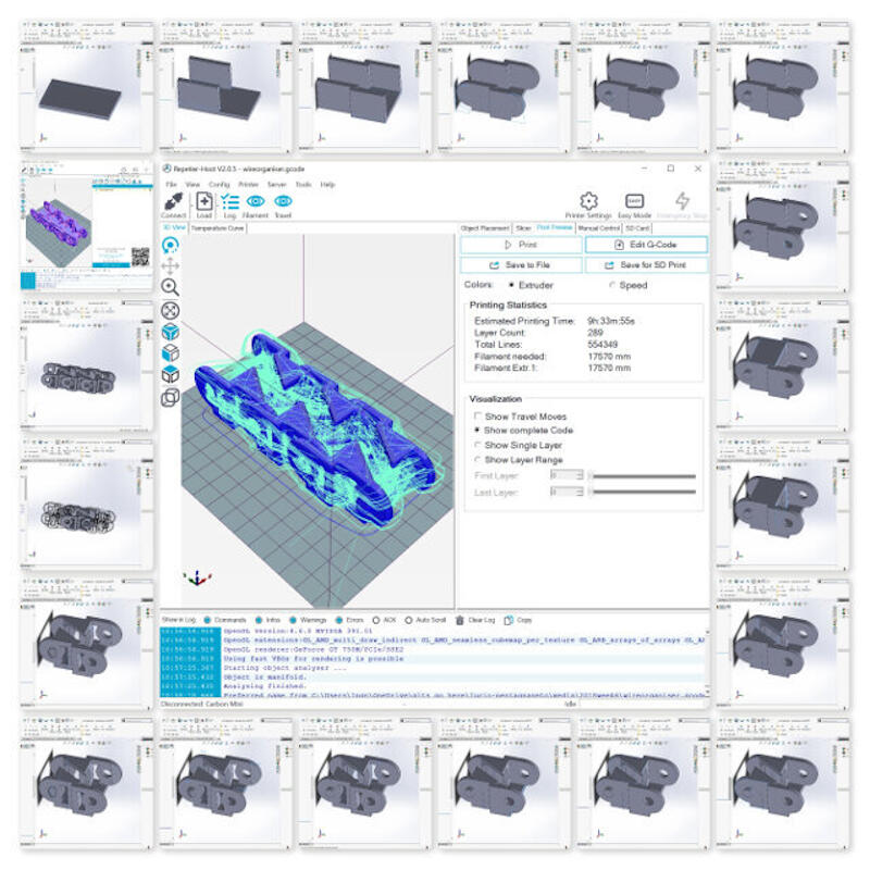
- In visualization, you can see layer by layer and understand how your settings will affect the print before actually printing.
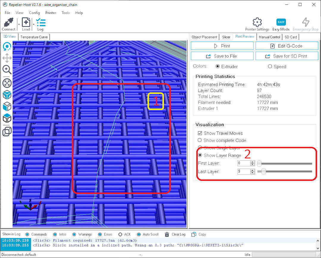
- The settings in the slicer show that the infill was rectilinear and at 20%, and the layer height was 0.2mm.
- Again, clicking show layer height and sliding the last layer will show the layers step by step.
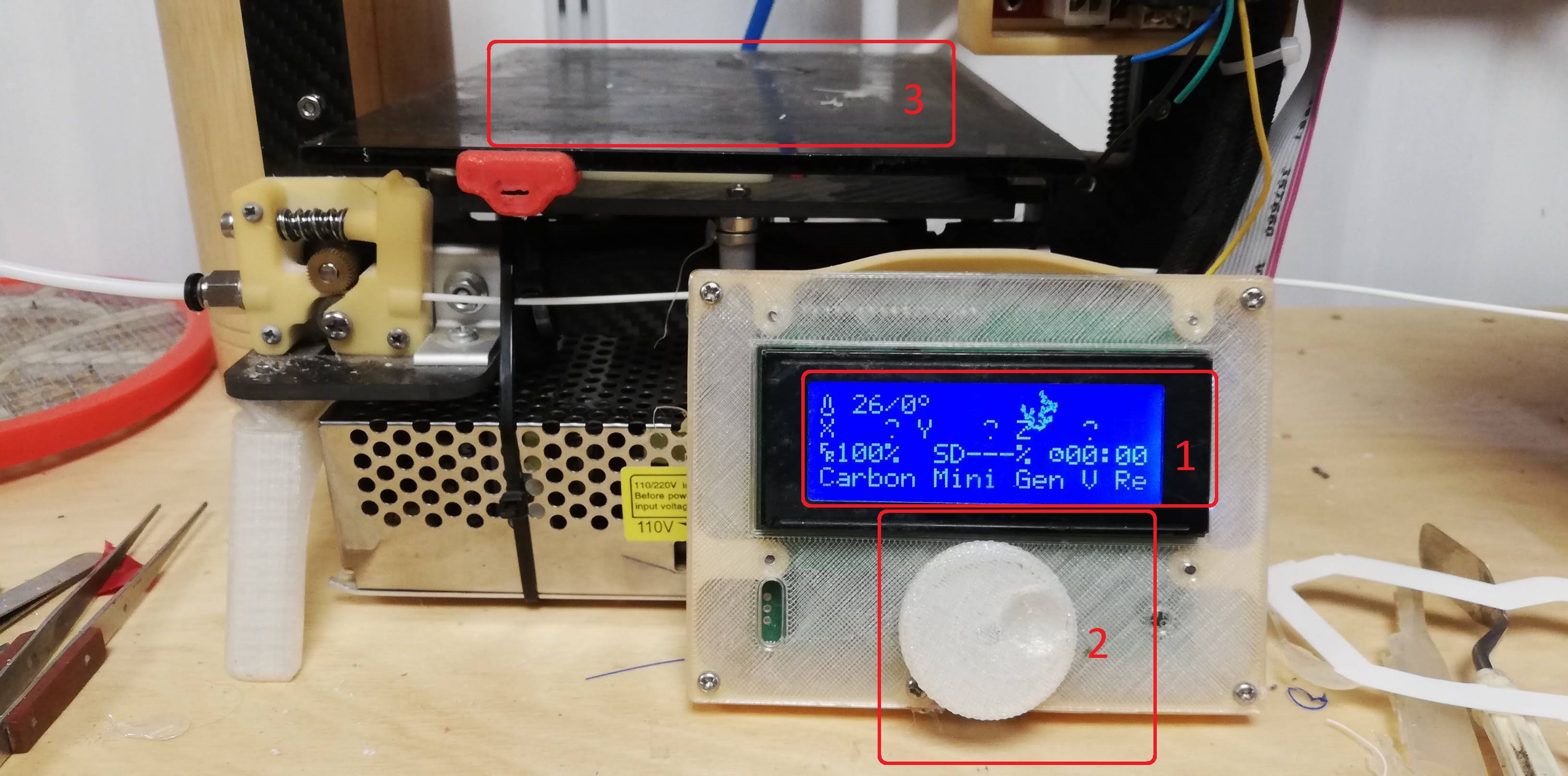
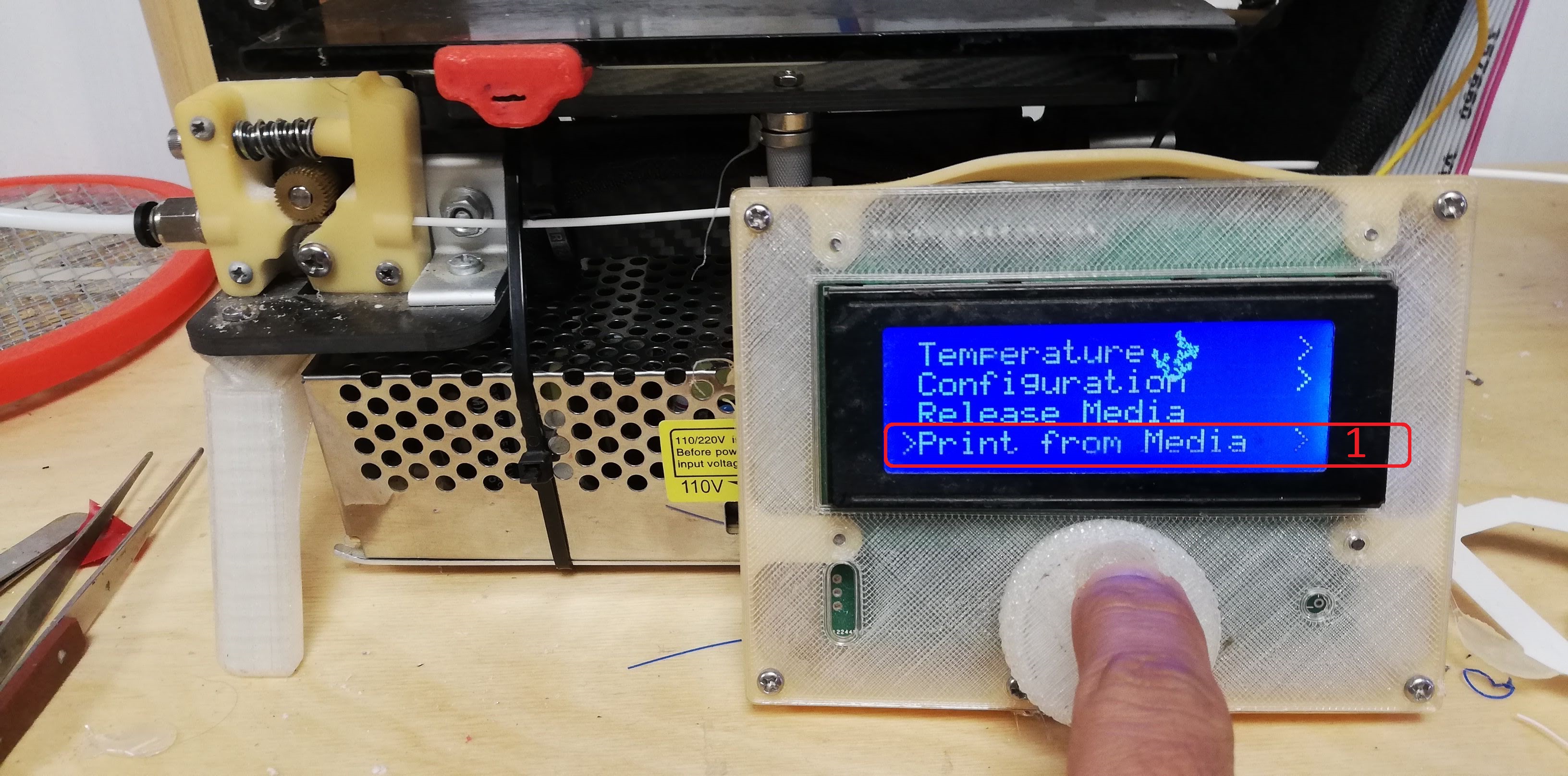
- With the SD card inside, check the LCD, which will show the nozzle temperature, top left.
- Then, press the rotary encoder to show the menu options.
- Scroll to "Print from media" and press the encoder knob.
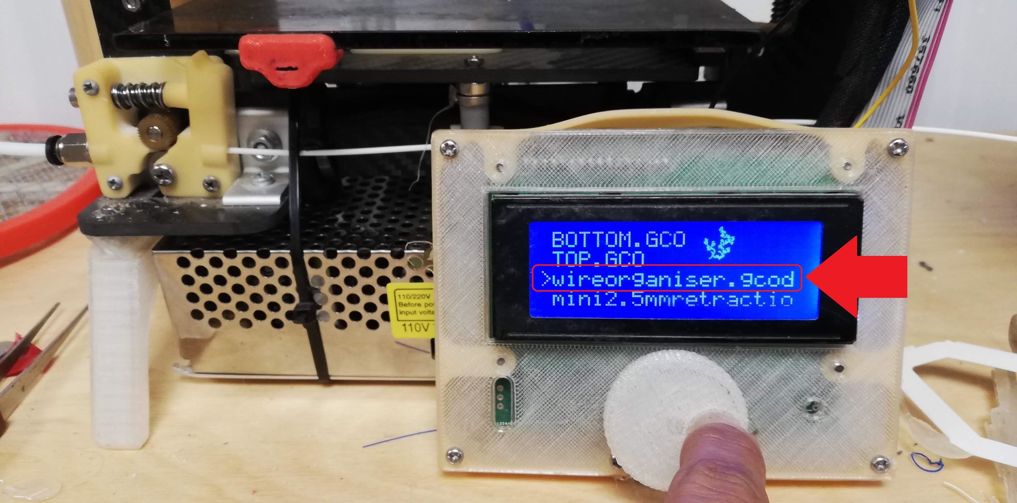
- Scroll to the desired file, press the knob, and the print will start.
- 3D Scanning
- For that part of the assignment, I used Autodesk ReMake. It relies on photogrammetry.
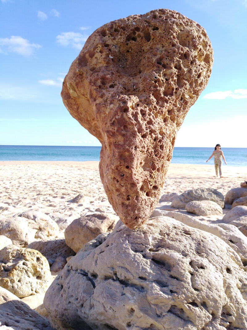
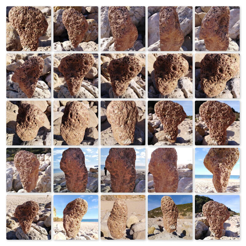
- Luckily, I was at the beach, and I saw a model that would be interesting: someone had balanced a large rock.
- The next step was to take around 40 photos from all angles, preferably without a moving background like people or clouds.
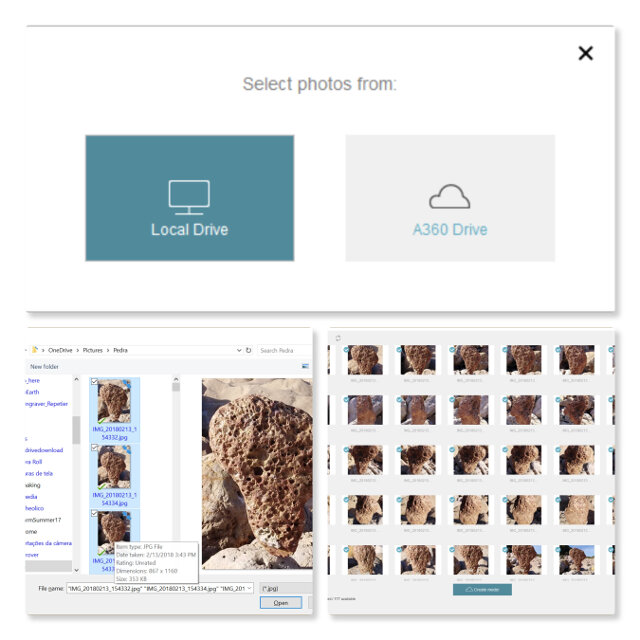
- Next, I uploaded the files to ReMake. It's important to select only good images and restrict background moving objects. After the upload is done, press create model. It can take a while during your model generation.
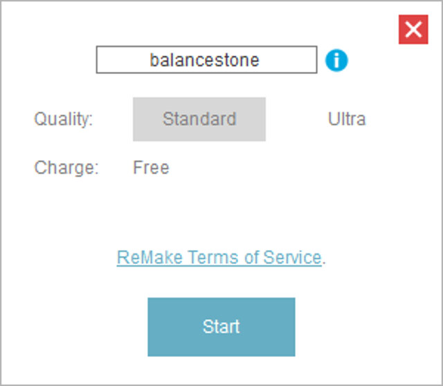
- After upload, choose an option in the generation process. I chose standard as it's free.
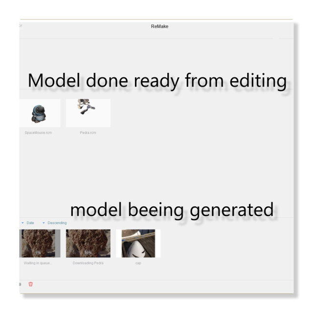
- On the lower part of the screen, ReMake shows models being generated and in queue. The top part shows models already done.
- With the model ready, you can click on it and enter the edit mode of ReMake.
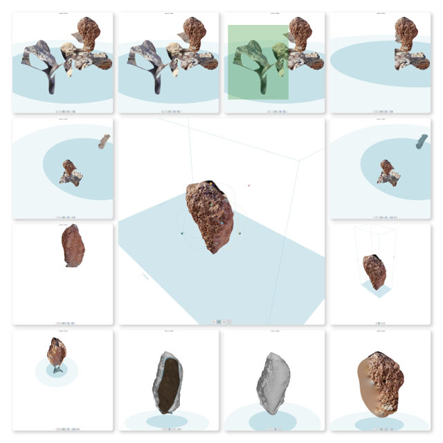
- I compiled the editing sequence in the following mosaic, in synthesis. I selected the undesired parts, deleted them, and filled the holes left. Finally, I generated an STL file that should be ready to print.
- Preparation of the Stone Model
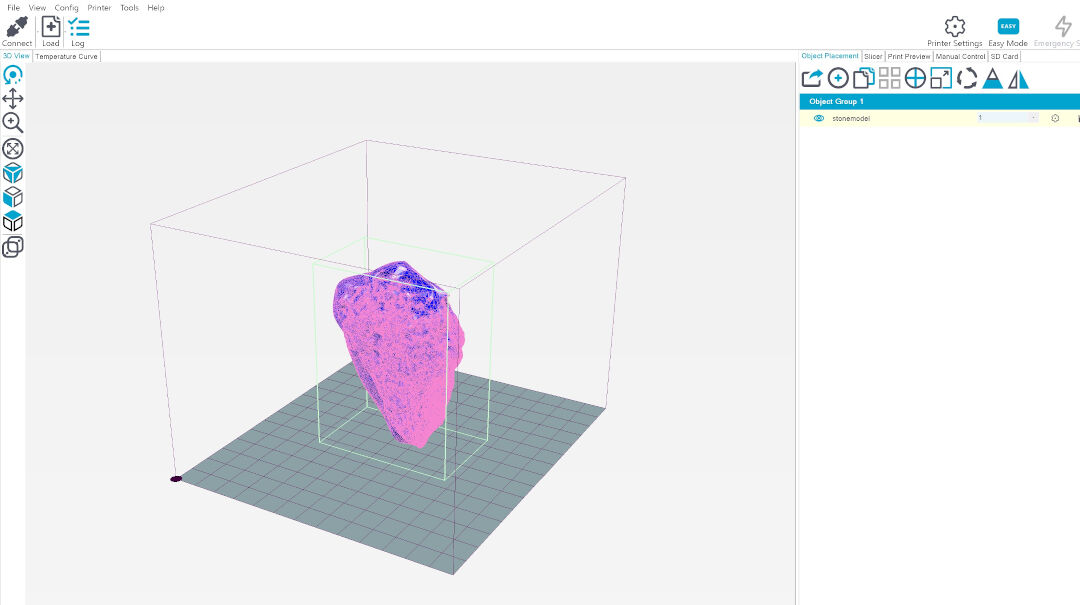
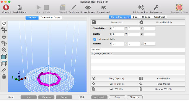
- I clicked on load in order to load the STL file into Repetier. STL file here.
- Next find the file in its directory and click ok
- If needed, it's possible to rotate, scale, etc. the model until it fits in the printer area. In my case, this was not necessary as the model fit.
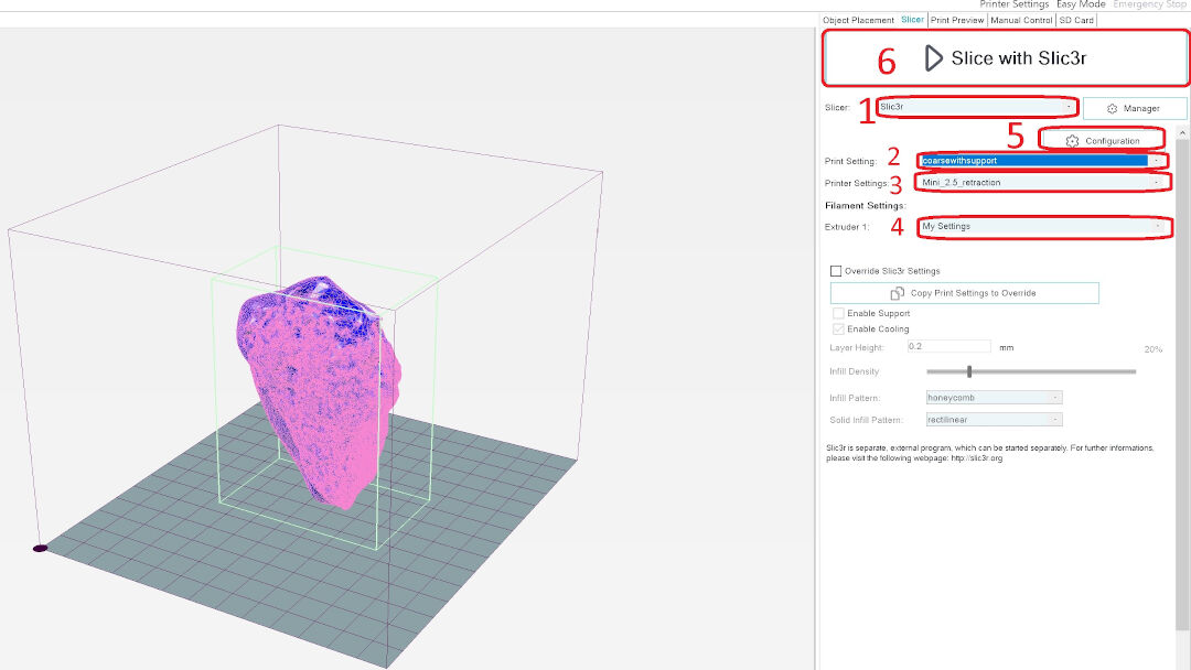
- On the tab "Slicer"
- I started by selecting the slicer software. I chose "Slic3r" (with a 3 instead of the letter "E"—yes, this is a confusing name).
- Next, I selected the pre-configured setting "coarse with support".
- Then, the best option according to the previous tests: Mini 2.5 retraction.
- On Extruder, there is only one pre-configured in this printer, so no choices are available.
- Advanced configurations are available in the "configuration" option, but in my case, it was not needed as the already tested pre-configuration should work fine.
- Finally, click on "Slice with Slic3r" to start the slicing process.
- Now the model is ready to be printed. This can be done by clicking on the button "Print". The top arrow points to the statistics of the print; it would take 1:41 minutes to print the scanned model, which I chose not to do. In the lower arrow, it's possible to see the support material that was prepared for the print.
- G-code generated:
The G-code generated can be downloaded with the link above, but I extracted the beginning of it here in order to show a few of its statistics:
; generated by Slic3r 1.3.1-dev on 2020-05-31 at 20:04:21
; external perimeters extrusion width = 0.44mm (3.38mm^3/s)
; perimeters extrusion width = 0.48mm (7.54mm^3/s)
; infill extrusion width = 0.48mm (10.05mm^3/s)
; solid infill extrusion width = 0.48mm (2.51mm^3/s)
; top infill extrusion width = 0.48mm (1.88mm^3/s)
; support material extrusion width = 0.44mm (6.76mm^3/s)
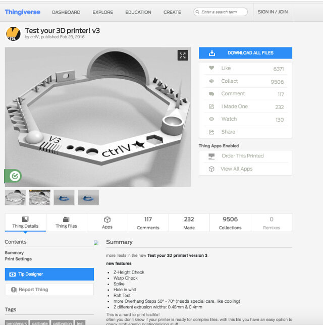
On the 3D printer test model's page, I downloaded the design and noted the parameters it tests, such as:
Bellow is the 3D print test model:
The author also provides an image for reference when checking the print.
- This Slic3r is the slicer software itself that is buried deep in the Repetier. Its realms are not for the faint of heart, where wrong moves here, or should I say settings, might render catastrophic results in your prints.
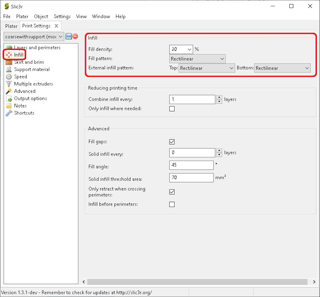
- Now we are in the Print Settings tab.
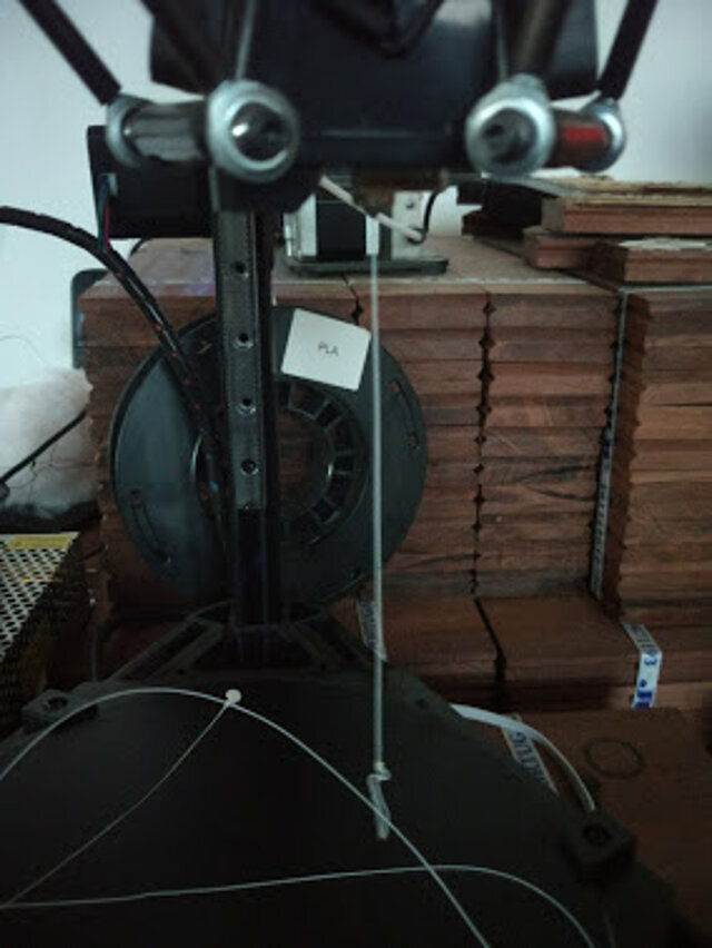
Now, this sub-class of the Print settings is infill. One can save a lot of time and money here. Someone once said they are both the same; frankly, I'd rather own the first than the second. The infill I have is 20%. I am not a cheapskate; I believe 20% is enough. After all, the ephemeral pieces this printer expels are rarely worth using all this corn. Ah, did I mention I am using PLA, a derivative of corn? Of course not; that's later in filaments... So, for now, believe me, 20% is enough for almost all prints. If you need to tow a truck, go crazy, use 100%. If, on the other hand, you want to make a delicate vase, 0% will leave you a hollow print.
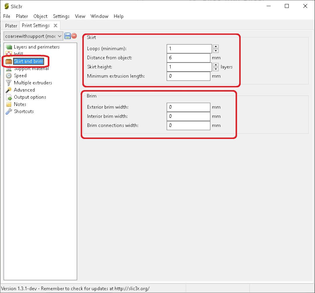
In this subsection of Print settings, the famous Skirt and Brim, the savvy fabber can use Brim instead of the ridiculous and wasteful rafts done by those who won't take the time to level and calibrate their printers. By using a wide brim, you make sure your print won't detach from the bed. Brim basically consists of lines next to each other and attached to the print; it's great for a spiky model's base, or just corners that want to take off from the print bed, causing "warping". The skirt is used to kind of clean one's noose—I mean nozzle, yes, the printer nozzle, the part that the filament comes out of. This setting will extrude a line around the model to be printed, especially useful when filament promiscuity is the case, so when changing colors or filament types, be sure to either extrude in the air or add some skirt before your print.
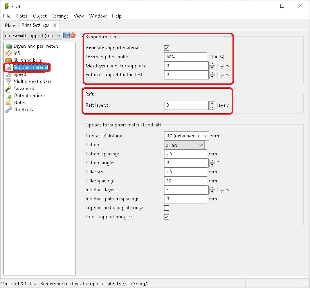
The subclass of Support material I leave for the people who won't challenge their machines for the ones who don't care to calibrate and level.
With Support material, you use this for overhangs. Support builds under your model in places where the negative slope is too steep, in order to prevent a real bird's nest by free-forming under your nose—I mean nozzle.
Raft... how I hate rafts! I don't even want to talk about rafts. I wonder how much popcorn has been erased from the universe by the usage of rafts! Well, like the name implies, no one wants to be on, or use, a raft. It's for emergencies and should be kept only for that. It creates a waste of material that will poorly compensate for the lack of leveling; it's for the lazy, but in the end, promotes more work, as the underside of the print will never be as smooth as the part printed directly on glass. Support also does that. Try printing with support and then spend the next hours post-processing your prints—super fun stuff.
The class of filament settings deserves not much time as they are straightforward. If your filament supplier cares about you, they will give you the temperature at which to print on a label on the sides of the box or spool. The diameter is, and has always been with me, 1.75mm. The thinner diameter is easier to push than 3mm, the other standard in filament thickness. After all, we are pushing filament through a nozzle with a 0.4 mm diameter; that's thin, so choosing a printer that takes a thin filament is better!
Here in printer settings, we find nozzle size. I use 0.4 mm. Next, my preferred setting in these tests—well, practically the only one I messed with—is "retraction".
As the designer, engineer, and technician of my printers, there's little that I haven't tried before.
The retraction, yes, the retraction, will depend on many factors. Too much retraction, and the filament can get stuck in the nozzle, guaranteeing one a lot of fun fixing/disassembling a nozzle where the filament froze in higher levels. It's always fun for geeks like me to fix that, NOT! Too little retraction, and you will have spider webs all around your towers. So, this is a setting that needs to be tested and tested, until, like many other settings, you do trial and error until mastered to what resembles perfection, if that even exists in FDM, of course.
Click here for the process of slicing and creating the file with the g-code to print.
| Parameter | Results | ||
|---|---|---|---|
| Mini | Delta | ||
| 1 | Nut, Size M4 Nut should fit perfectly | Yes | No |
| 2 | Wave, rounded print | Yes | Yes |
| 3 | Star, Sharp Edges | Yes | Yes |
| 4 | Name, Complex Shapes | Yes | Yes |
| 5 | Holes, Size 3, 4, 5 mm | 2.9, 3.9, 4.9 | 3, 4, 5 mm oval |
| 6 | minimal Distance: 0.1, 0.2, 0.3, 0.4, 0.5, 0.6, 0.7 mm | 0.1mm not good | 0.1, 0.2, 0.3 not good scale wrong 6.5mm instead of 7mm |
| 7 | Z height: 0.1, 0.2, 0.3, 0.4, 0.5, 0.6, 0.7, 0.8, 0.9, 1.0, 1.1 mm | 0.1mm printed with 0.2 and 1.1 with 1 | Yes |
| 8 | Wall Thickness: 0.1, 0.2, 0.3, 0.4, 0.5, 0.6, 0.7 mm | didn't print 0.1, 0.2 next walls printed as 0.5 until last as 1mm | Yes |
| 9 | Bridge Print: 2, 4, 8, 16 mm | Printed as 2.85, 3.9, 7.9, 15.8 | Yes |
| 10 | Sphere, Rounded Print 4.8mm height | 5.1 | Yes |
| 11 | Sphere Mix, 7 mm height | 7.15 | Yes |
| 12 | pyramid, 7 mm height | 6.95 | Yes |
| 13 | Overhang: 25, 30, 35, 40, 45, 50, 55, 60, 65, 70° | Yes | Yes |
| 14 | Warp, does it bend? | no | Yes |
| 15 | 3D Print Font, optimized for 3D printing | Yes | Yes |
| 16 | Surface, Flatness | a bit rough | Yes |
| 17 | Size, 100 x 100mm x 23.83 (10mm width) | 99.45 x 99.8 x 23.2 (10.2 with) | Yes |
| 18 | Spike, minimum Layer Time, 21 mm height from Bottom (include Baseplate) | 15mm | Yes |
| 19 | Hole in Wall, 4 mm diameter, check for proper print | Yes | Yes |
| 20 | Raft Test, raft should be just under the model | didn't test | Yes |
| 21 | Retract Travel, check retract settings for longer travel | almost no oozing | Yes |
| Conclusion | For an FDM printer, I believe the result is very good. The size differences are probably due to PLA shrinkage. |
This design is either too hard or even impossible to do with subtractive techniques due to its shape and details, which are inaccessible to a 2-axis CNC or even a 3-axis one.
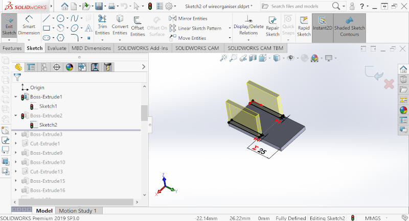

The result: