Mechanical Design (WEEK 19)
Week Objectives
- Design a machine that includes mechanism + actuation + automation
- Build the mechanical parts and operate it manually
- Document the group project and your individual contribution
This week was very special because this week we need to make a group project with colaborating with each other
Team Member's
For this week we have a 4 member team to complete our assignment and there name's are as follow
1. Pulkit Talwar
2. Afsha rana
3. Neeraj Gupta
4. Sreedhar Ramaswamy Pushparaj
Project Idea
Automatic Hand sanitizing Machine
This video is from youtube and our design work is same to this one
- Components Required
- 2 X DC motor
- 1 X ultrasonic sensor
- 1 X Arduino Unoboard
- Male - Female Jumper wires
- 1 X Small Breadboard
- Acrlyric sheet for frame
- 3d printed part for mechanism
- 2 X spray bottles for sanitiser
Workflow Dstribution
For this Project we have decided to Distribute work in 3 parts
1. CAD Design and Simultion part
2. Electronic Design and Progrsmming part
3. Fabrication and Assembly part
I got the electronics part as , for this week , if you like to see other's work please click on this link
Well for information Afsha mam got the designing part as she has good knowledge of designing and neeraj sir got fabrication part as he is the only one with lab access as , we are in lockdown period
Electronics
Well my target for this week is to create an electronic connection , in which when a person place his/her hand inside then the motor hould actuate and the persons hand will get sanitized , for this I opted for the most easiest way like connectingeverything with arduino
Components i required
1. Arduino Uno board
2. A D.c motor
3. HC-SR04-Ultrasonic Range Finder
4. male female jumper wire
5. Breadboard
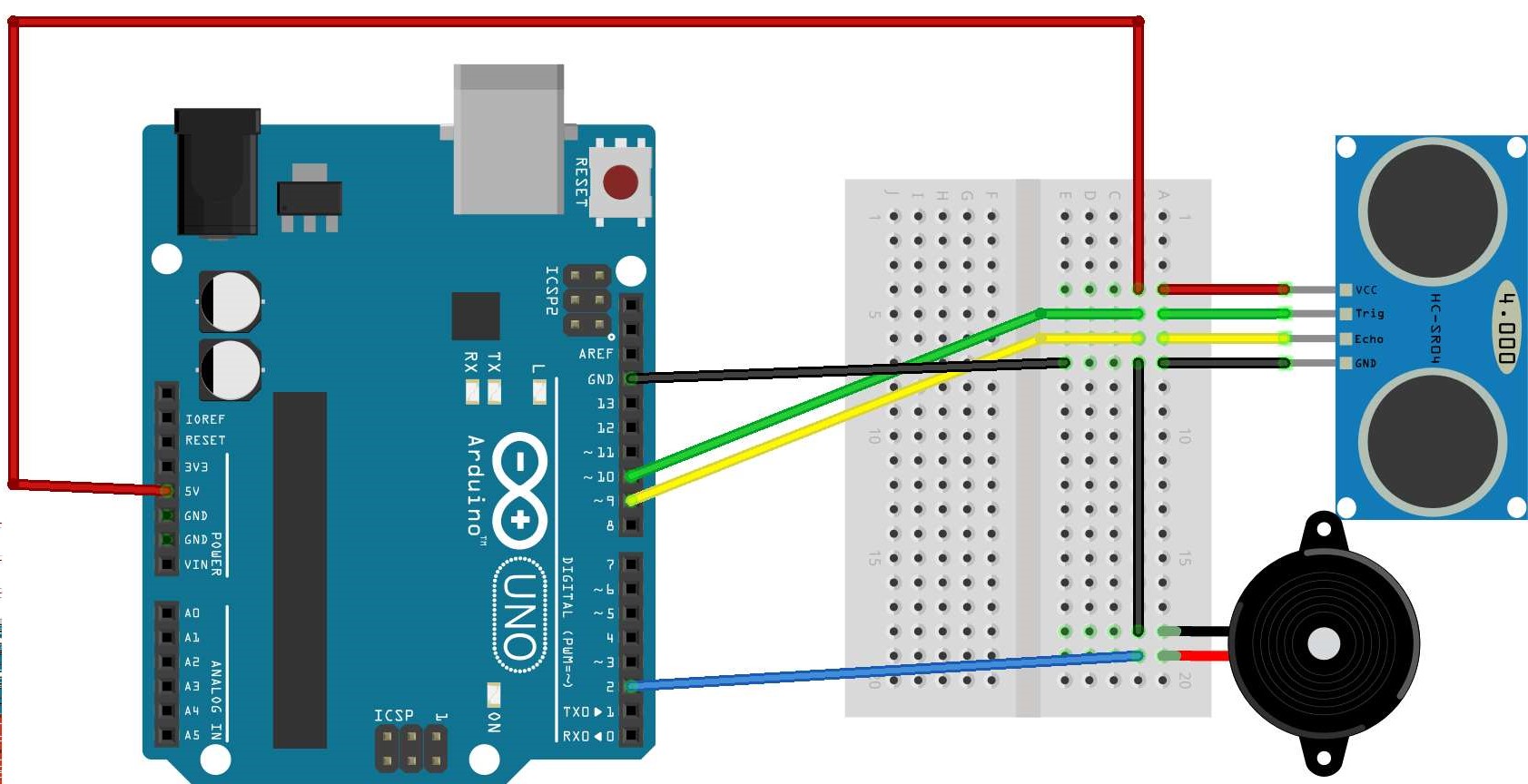
Connections should be made like this , you are require to connect VCC of Arduino to VCC same goes for GND also connect the GND of motor to the same point
then connect PIN 12 to trig pin of sensor and pin 11 to echo pin of sensor and last not least connect Vcc pin of motor to PIN 2 of arduino ,its a PWM pin
After the connections are made you just rquire to upload the code which i have given below
                                                int pinTrig = 12;   // connect the trigger pin of ultrasonic sensor -----> pin 12 .
                                                int pinEcho = 11;    // connect the echo pin of ultrasonic sensor ---->  pin 11 .
                                                int pinMotor = 2;    // connect the motor pin 2 .

                                                long duration;

                                                int distance;  // distance between object and ultrasonic sensor.

                                                void setup() {


                                                // put your setup code here, to run once:

                                                Serial.begin(9600);

                                                pinMode(pinTrig, OUTPUT);
                                                pinMode(pinEcho, INPUT);
                                                pinMode(pinMotor, OUTPUT);

                                                }

                                                void loop() {
                                                // put your main code here, to run repeatedly:

                                                digitalWrite(pinTrig, LOW);
                                                delayMicroseconds(2);  // Delay for 2 Usec
                                                digitalWrite(pinTrig, HIGH);
                                                delayMicroseconds(10);    // Delay for 10 Usec


                                                digitalWrite(pinTrig, LOW);
                                                duration = pulseIn(pinEcho, HIGH);
                                                distance = duration*0.034/2;

                                                Serial.print("Distance:  ");
                                                Serial.println(distance);


                                                if(distance <= 18){   // the distance is in centimeter  you can set your value I select I select 18 because it my lucky number :)
                                                digitalWrite(pinMotor, HIGH); // Start the motor


                                                }else{

                                                digitalWrite(pinMotor, LOW); // Stop the motor


                                                }

                                                }
I am listing the code here in case you require to use the same code , just click and copy the code
Circuit explanantion
As i have given the pinout above you can see the connections are a piece of cake and the coding is also not that much of deal
I have used the HC-SR04- Ultrasonic sensor for this circuit as it is a very easy to use sensor , it uses SONAR to determine the distance of an object just like the bats do. and have an impressive range
of 2 cm to 400 cm
* This code implies that we defined the Trig pin of the sensor to pin 12 (Trigger pin is an Input pin. This pin has to be kept high for 10us to initialize measurement by sending US wave) and echo pin
to pin 11 ( Echo pin is an Output pin. This pin goes high for a period of time which will be equal to the time taken for the US wave to return back to the sensor.) and Motor pin to Pin 3
* so what basically happens is that my ultrasonic sensor is placed on the bread board and connected to my arduino and facing Horizonatally, when some obstacle comes across which is less than or equal
to 18cm in this direction the motor will start rotating. and the basic purpose is to start the actuation mechanism and spray disinfectant .
If you want to know more please click on this link , i learned to make this circuit from Arduino's Project hub page
Throught this video , you can see that my experiment worked
| Name | Description | Quantity | Price/Pcs | $ |
|---|---|---|---|---|
| ARDUINO UNO R3 | Will be the brain of my cicuit | 1 | Rs. 259 | $3.50 |
| HC-SR04- Ultrasonic sensor | For movement detection | 1 | Rs. 75 | $1.01 |
| 9v D.c motor | For Actuatiion | 1 | Rs. 189 | $2.56 |
| Jumper wires | For connections | 2 | Rs. 55 | $0.71 |
| Total | Rs. 578 | $7.78 |
This is the Bill of the material for the Electronics connection which i made using Arduino
Plan 2
Well if we think the Plan A where we were using Arduino works well but We were asked by our college to make more of these sanitizers , so the previous option was not viable as for every machine using an arduino is too much costly and making PCB Having an IC is also equivalent to this due to it also have good costs so i need to come up with another plan
so i searched the arrangements which could be used in the current scenerio and i found the following circuit online.
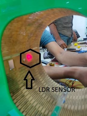
It worked on the basic principle of LDR sensor i.e.When there is no light on the ldr sensor its resistance can reach to 2-3 Million Ohms and no current can pass through it and when light emits resistance
reduces drastically to few kilo ohms depending ont the intensity of Light

This is the circuit which we took as the reference for making our electronic circuit. Initially we were applying the circuit opposite to it where the circuit was behaving in an opposite manner.
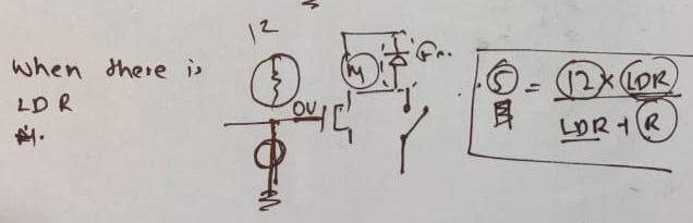
For ex, i wanted to run the motor when there is no light on the ldr from the laser diode but it was doing the opposite then we did some brainstorming in understanding the concept.The mistake we were doing was that we placed the ldr on the wrong position it has to be on the place where we added the resistor
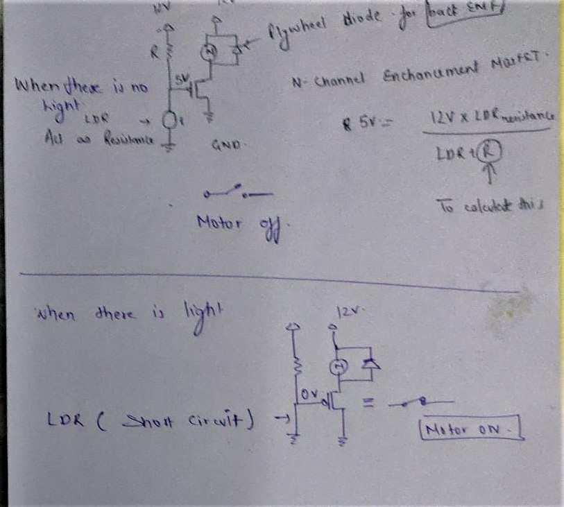
From the above circuit you will understand what i am trying to say , there are 2 case
1. When there is no light
2. when there is light
i made the circuit such that when light falls on the ldr then the current does not reach the motor or the switch of the mosfet remains open. And when the light does not fall on it (for example the hand restricting the light of the laser diode) the switch will be closed and the curent will go to the motor.
We have also placed a Diode because of the Back EMF craeted in the DC motor. The diode will stop the current due to back emf to flow in the circuit.
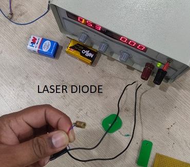
Initially we were using the 9volt battery but the discharge of the battery was at a very high pace so we thought of using the 12volt supply. Then we had to recalculate the resistor value and add that with the laser diode and with the ldr.
| Name of components | Quantity |
|---|---|
| LDR Sensor | 1 |
| 5V Laser diode | 1 |
| 9v D.c motor | 1 |
| IRFZ44N N-channel mosfet | 1 |
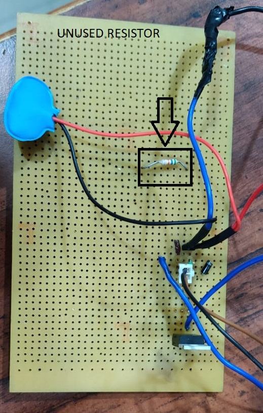
| 360K Ohm resistor | 1 |
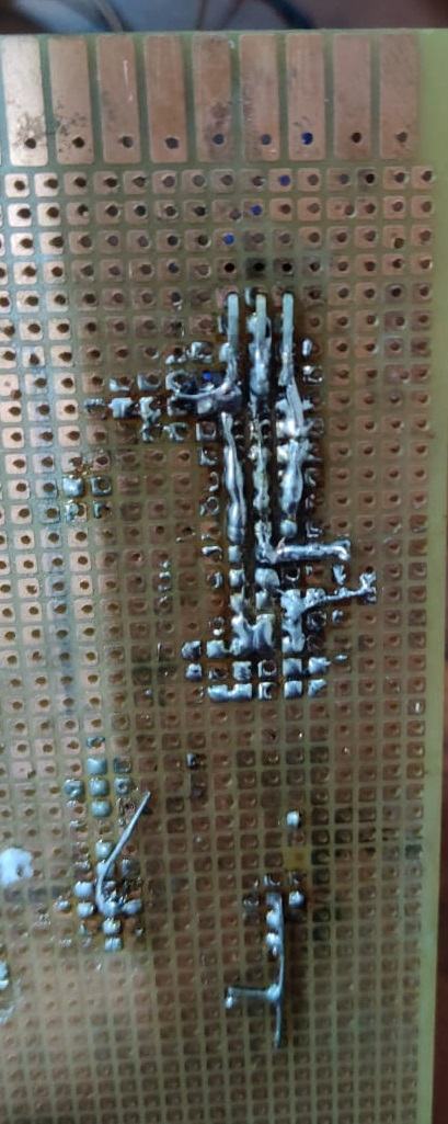
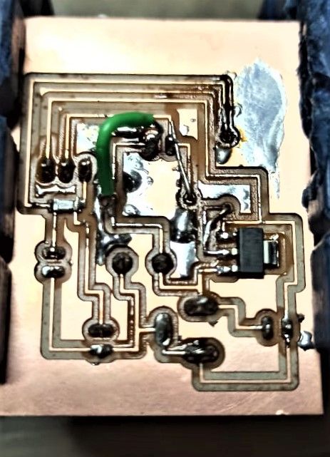
This is the soldering which we have done to connect the components to get the required functionality only to verify our concept that why i used perforated board and if it works i planned to make PCB later.
I added Ldr as well as
I added Ldr as well as Light emiting diode to system
This was our first test run
It worked perfectly , now its time to make its PCB
FAB SANITIZER MARK 1 PCB
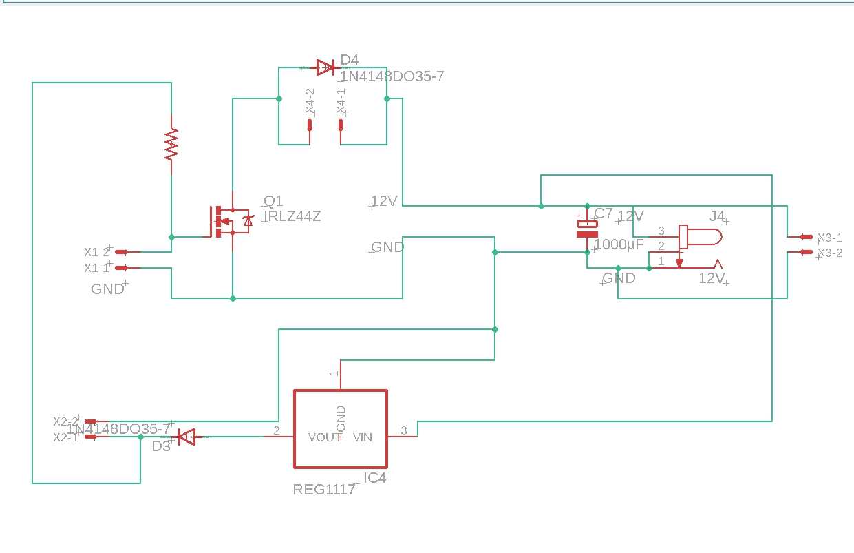
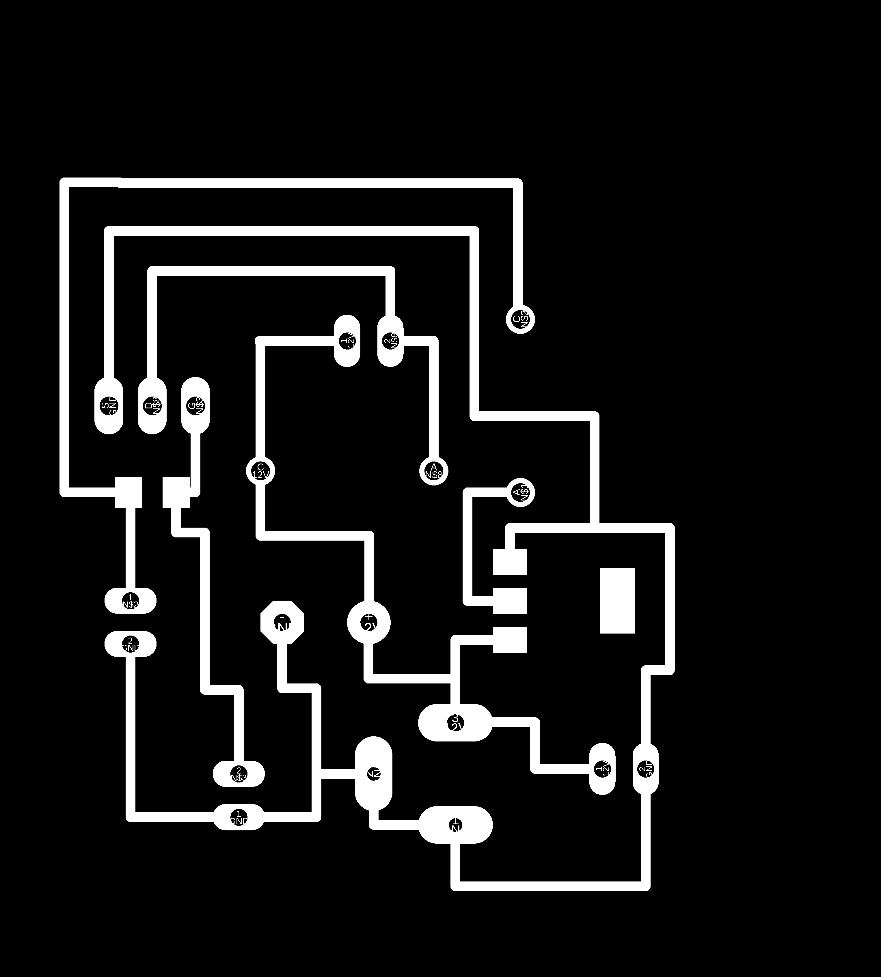
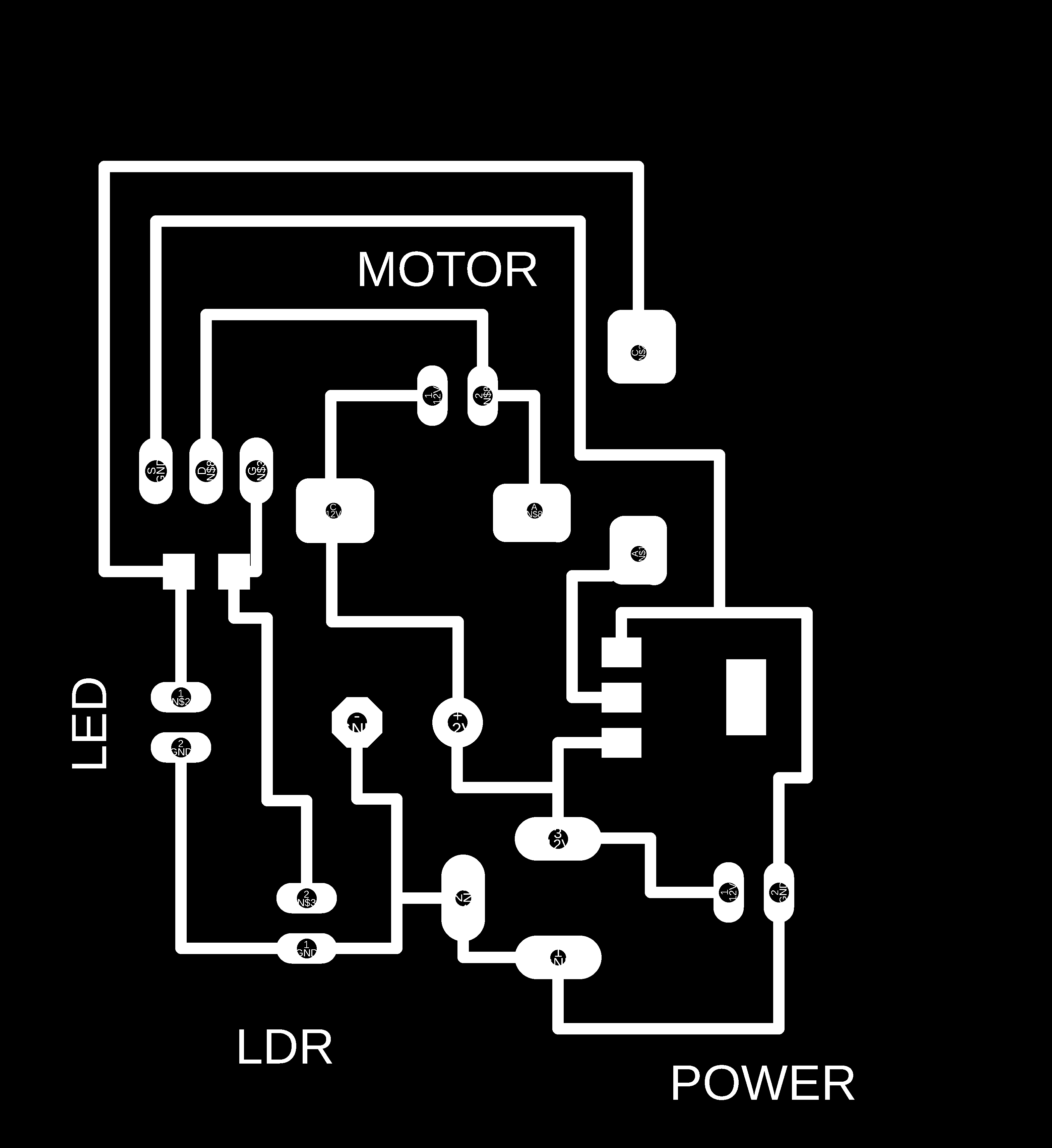
This will be my schematic for the pcb
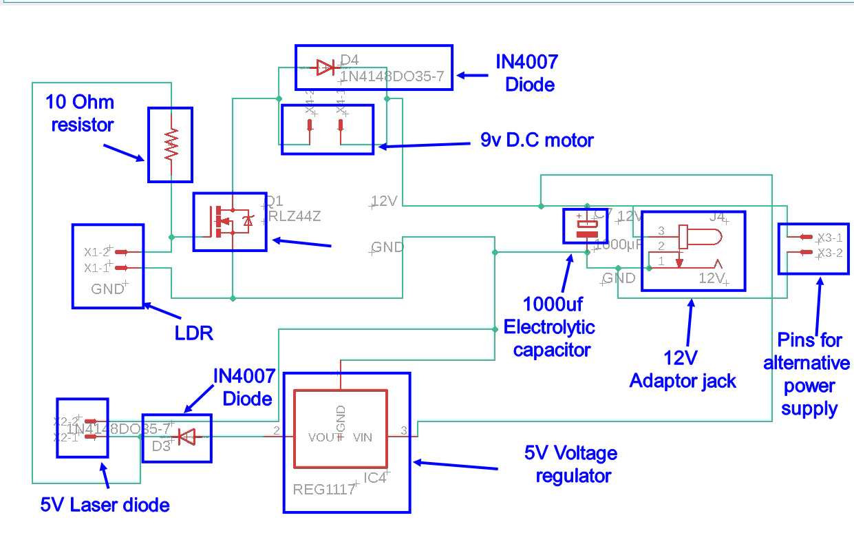
| Name | Description | Quantity | Price/Pcs | $ |
|---|---|---|---|---|
| LDR Sensor | will be the main input device and also act as a million ohm resistor when no light is there | 1 | Rs. 5 | $0.068 |
| 5V Laser diode | Act as a light source and also act as a trigger | 1 | Rs. 20 | $0.27 |
| 9v D.c motor | For Actuatiion | 1 | Rs. 45 | $0.61 |
| IRFZ44N N-channel mosfet | Will act as a Gate for this analogue circuit | 1 | Rs. 20 | $0.27 |
| 10K Ohm resistor | For safety of LDR | 1 | Rs. 3 | $0.041 |
| IN4007 diode 1A 1000V | To control back emf | 2 | Rs. 10 | $0.14 |
| 5V REG1117 Voltage Regulator | To reduce 12V to 5V | 1 | Rs. 7 | $0.10 |
| 2 X 1 JST Male Header Pin | To connect different components | 4 | Rs. 8 | $0.11 |
| 12V D.C Female power jack | To connect 12V adaptor to it | 1 | Rs. 10 | $0.14 |
| Total | Rs. 128 | $1.73 |
This is the list of components used by me for designing PCB
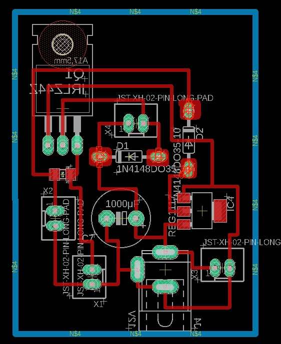
This is the final design of board for the pcb
And if you want to download the files for the pcb , by clicking on the link you can download the Eagle files, .rml files and PNG files as well
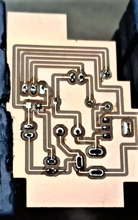
FAB SANITIZER PCB MARK1.2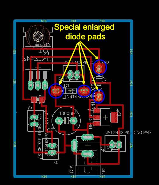
You may wonder what are these blobs in the circuit , these are special altered pads , i was forced to make these for Diodes , as the conventional padding for diode were too thin and after making holes they were too fragile and broke very easily
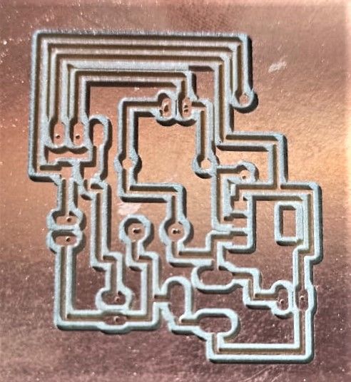
FAB SANITIZER PCB MARK 1
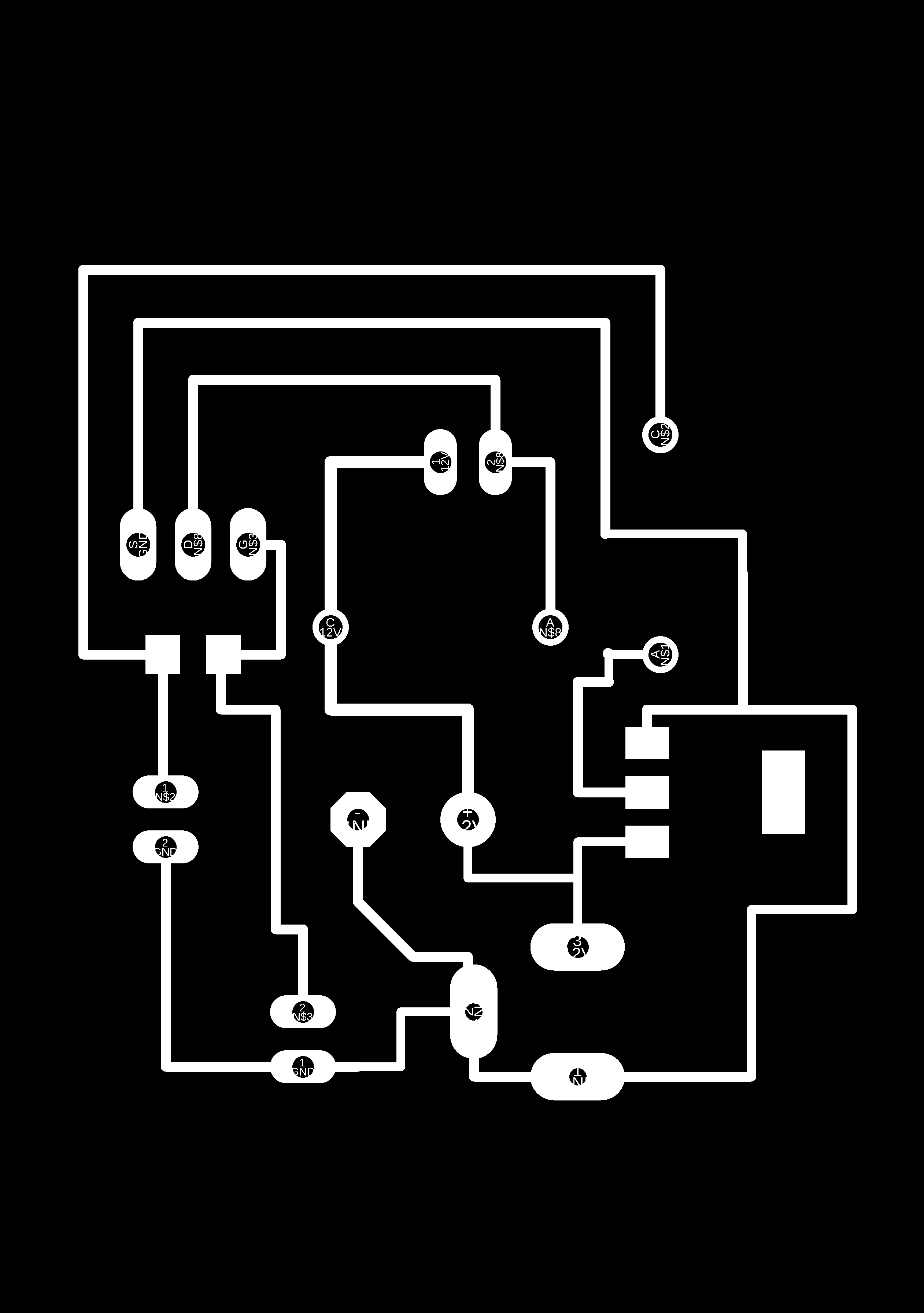
This is the png Image for the first PCB i made for sanitizer , as you can see the pads for diode are too thin , and when i soldered it , they came off and i was not able to work with it
As you can see the size of track from this image that they are eally very thin
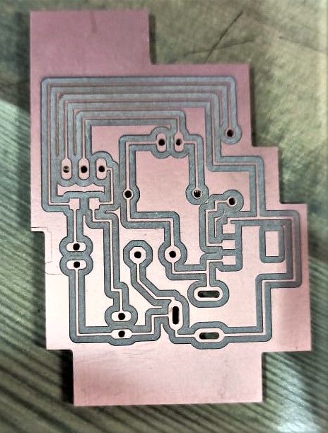
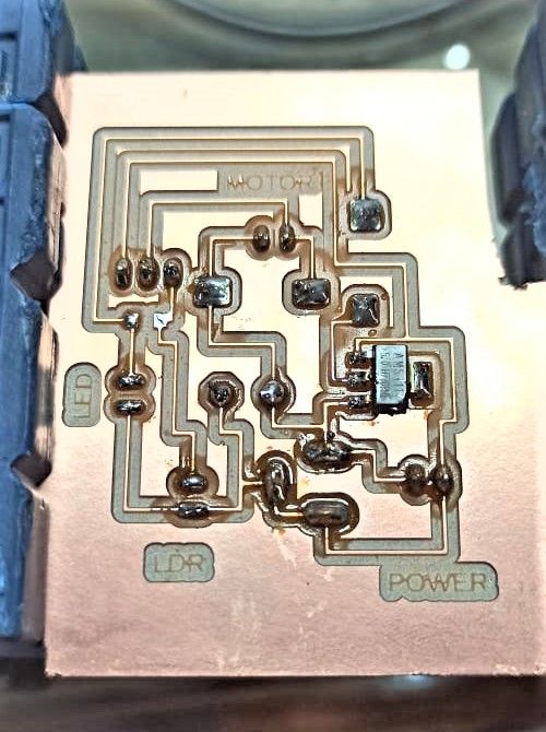
This is the image before soldering the components , i used to add a little bit of solder before placing the components , which helps when adding all the components
This is the image of failed pcb as diode tracks were removed , i have also de-solder the components so i can use it in next pcb
FAB SANITIZER PCB MARK 1.1
Then to save the tracks i have incresed the track width from 16 mil to 24 mil , so the chance of track's ripping can be reduced
In this pcb overall tracks are bigger but component pads like for diode remains same
Again same thing happens due to less space on pads after hole the ,pads get rip off and now this is getting on my nerve so i designed a new pcb with more improvement.
FAB SANITIZER PCB MARK 1.2
For this time i manually added added a thicker tracks for diode , so this problem doen't occur
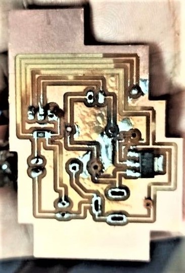
I think this is one of the best soldering i have done yet and the tracks didnt came out this time
Plan 3
Well when we presented this project for Global evaluation , our Global Evaluator has pointed that , this project lacks Automation as there was not digital logic circuit , we were using an analogue circuit as it is good from commerial point of view it is doen't qualify for this weeks evaluation criteria , so we decided to do something about this and tried to come up with an digital/ logic based circuit
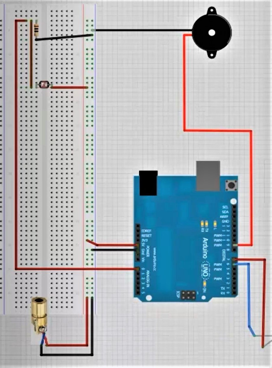
So meet the requirements of the evaluation we asdded an arduino to circuit and programmed it as well and this is the pin diagram for something similar to what we have done , this image and code were taken from instructables site , if you like you can go on there website by clicking on this link
                                                int sensorPin=A0;
                                                int sensorValue=0;

                                                int motorPin=10;

                                                void setup() {
                                                Serial.begin(9600);
                                                pinMode(sensorPin,INPUT);
                                                pinMode(motorPin,OUTPUT);
                                                }

                                                void loop() {

                                                sensorValue=analogRead(sensorPin);

                                                if(sensorValue<=600)

                                                {
                                                digitalWrite(motorPin,HIGH);
                                                }
                                                 else {
                                                digitalWrite(motorPin,LOW);
                                                }
                                                Serial.println(SensorValue);
                                                }
I am listing the code here in case you require to use the same code , just click and copy the code
This code implies that we defined the LDR pin as input and Motor as output. By analogRead we can read the value of LDR on serial monitor.As we got when the laser diode fall on ldr,Its value is greater than 600 and there was no laser light the value falls so it will turn the motor on and made motor pin high as its on Pin Number 8.
This is the code which we have taken from instructables and modify it according to our requirement like :
* Removed the leds which were initially installed in the circuit.
* Changed the buzzer with motor
This video is all the testing our circuit using Arduino uno , and you can see it woks properly
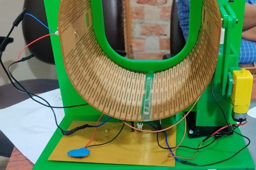
Time to test it with the whole machine
This is the final video after proper packaging
Some improvements
* "That project is fine for mechanism and actuation, but doesn't show automation. The automation component has to have some element of coordinating a sequence of activities; an analog circuit just connecting a sensor to a transistor
isn't adequate. Also, I expect to see a schematic and PCB design; they need to do better than soldering a perf board.
* "It would be adequate if they added a control loop, with a processor setting the duration of dispensing the sanitizer, as commercial units do."
These were some comments which were given to us by our Prof. Neil Gershenfeld , so we have worked on all the points except second one , so we work on the second point and is given here
                                                int sensorPin=A0;
                                                int sensorValue=0;

                                                int motorPin=10;

                                                void setup() {
                                                Serial.begin(9600);
                                                pinMode(sensorPin,INPUT);
                                                pinMode(motorPin,OUTPUT);
                                                }

                                                void loop() {

                                                sensorValue=analogRead(sensorPin);
                                                Serial.println(sensorValue);
                                                if(sensorValue<=10)

                                                {
                                                digitalWrite(motorPin,HIGH);
                                                delay(1500);     // motor remians open for 1.5 seconds
                                                digitalWrite(motorPin,LOW);
                                                delay(3000);     // motor remians open for 3 seconds

                                                }
                                                 else {
                                                digitalWrite(motorPin,LOW);
                                                }

                                                }
I am listing the code here in case you require to use the same code , just click and copy the code
To control the despertion of Sanitising liquide , we added a Delay of 1.5sec for working of the motor and restricted the dispertion to 5 spray at a time . The machine will spray 5 times in 1.5 seconds and then
it will detect another hand and then it will again run for 1.5 seconds. We have provided delay 1500 when the motor is open and the delay of 3000 when the motor is closed.
If the hand remains in the hole for more than 4.5 seconds then the motor will start again but the chances of happening that is very less.
From this video you can see how the controlled dispertion is working
This video is for the final video with all the packaging
| Name | Description | Quantity | Price/Pcs | $ |
|---|---|---|---|---|
| ARDUINO UNO R3 | Will be the main brain of this system | 1 | Rs. 259 | $3.50 |
| LDR Sensor | will be the main input device and also act as a million ohm resistor when no light is there | 1 | Rs. 5 | $0.068 |
| 5V Laser diode | Act as a light source and also act as a trigger | 1 | Rs. 20 | $0.27 |
| 9v D.c motor | For Actuatiion | 1 | Rs. 45 | $0.61 |
| 10K Ohm resistor | For safety of LDR | 1 | Rs. 3 | $0.041 |
| IN4007 diode 1A 1000V | To control back emf | 1 | Rs. 5 | $0.07 |
| Total | Rs. 337 | $4.45 |
Future Development oppurtunities
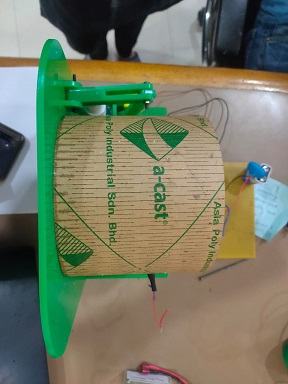
We have made the living hinge for the cylinder which is having slots in it because of which the santizer can fall on the electronic components placed beneath it. So it will be good to change it with some other material or arrangement.
We have installed only one bottle of sanitizer due to time constraint but it can be increased to two in future for higher effectiveness.
We have covered the bottle with acrylic which is causing us the problem of refilling the bottle. In the modified design we can eliminate this constraint.
Conclusion
It was a good experience working as a team for the machine as we explored a lot of options for the working of the machine. We managed to get it ready just before the time and to see the machine working the way we want it to is very exciting to see. For all of us it will be a good experience if we want to continue to design and fabricate more machines in the future.
Personally i will go with PLAN 2 as it is almost 3 times cheaper then PLAN 3 and 4 times cheaper than PLAN 1