For the first week we have to design the machine and operate it manually and automate the machine next week.
- I was thinking of making Motorized Camera Slider
- Neeraj sir was thinking of making 3D Printer
- Pulkit gave the Idea of Sanitizing Machine as this is the need of the hour.
This is the video link through which we are taking reference.
After lot of brain storming and group discussion, As we already thinking of making Sanitising machine and this idea also includes the criteria of machine making. With final discussion with our Remote insructor Puneeth we decided to go with Automatic Hand Sanitizing Machine
This week was of my strong point and I was given a task to design the Sanitizing machine and simulate the mechanism of motion which is desired for the criteria of this weeks assignment.
It is a kind of machine having mechanism to press the cap of spray bottles and the person without touching anything can sanitize his/her hand.
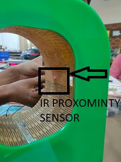
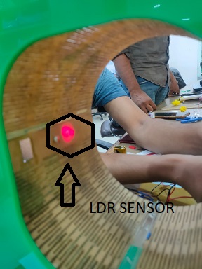
There is four bar Simple mechanism involve and to automate we will use laser diode and LDR sensor.
To create animation, I am very confident to work on Solid Edge ,I started design on Solid Edge
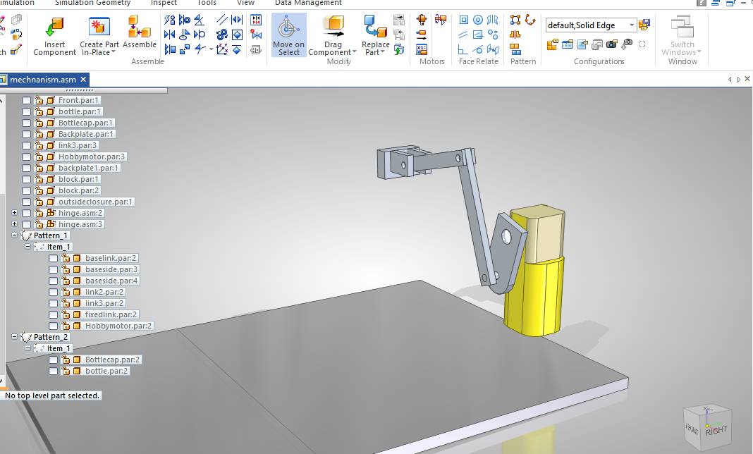
This is the four bar link mechanism in which one link is fixed and crank is connected to motor.
When crank rotates, the rocker or third link oscillate and press the cap of spray bottle.
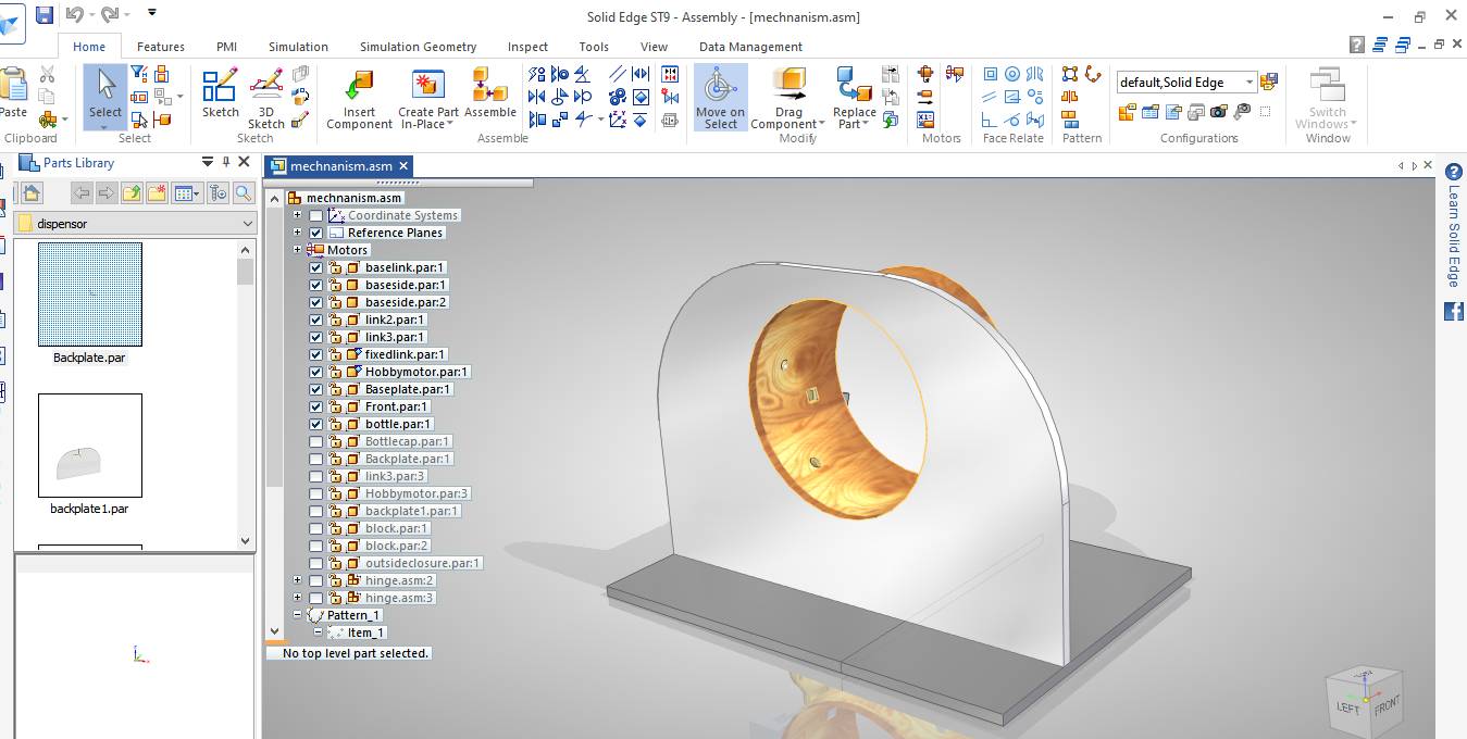
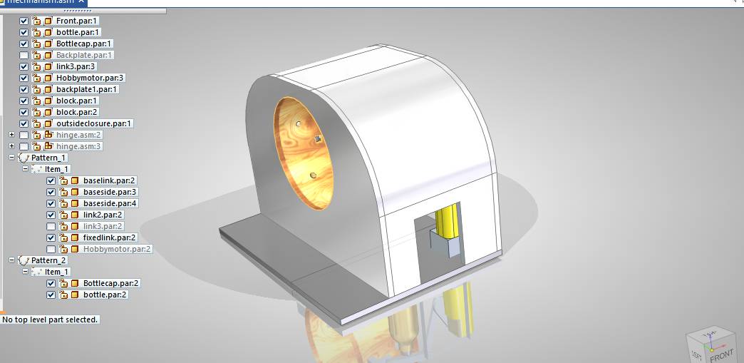
This is the front panel and shows the entrance for hands.
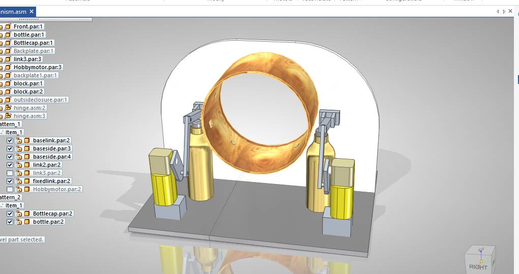
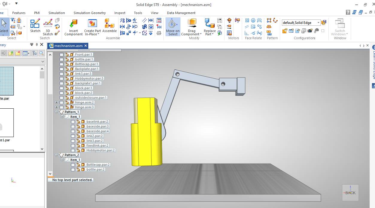
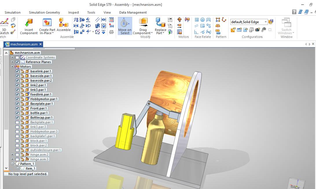
This is the overall design in which it shows placement of two spray bottles.
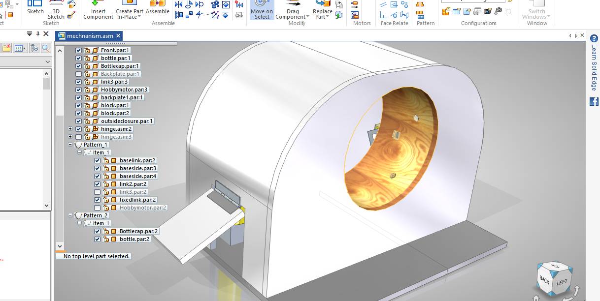
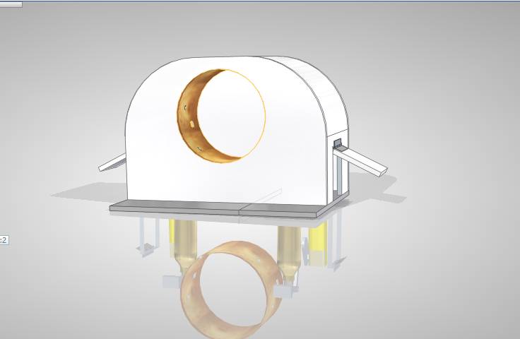
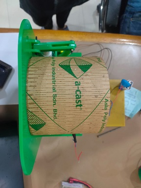
This is the design of whole machine and also the frame of machine.
For detailed info about the design you can visit this page.
This video shows the final animation of machine mechanism and actuation of motor.
We will work on it as soon as we get the access of lab.My fab mate Neeraj sir will work on Fabrication and Pulkit on electronics and programming.
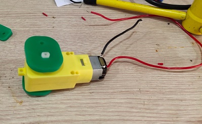
The difficlut task which i realsied was the motion of the knob. I wanted to test the power of the motor if that would be sufficent to do the task becuase the knob of the bottle was very tight and i was not coonfident if sufficient torque would be provided by the motor.
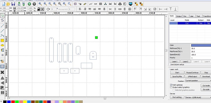
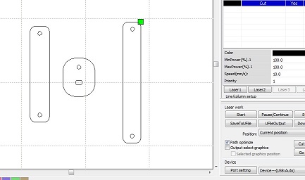
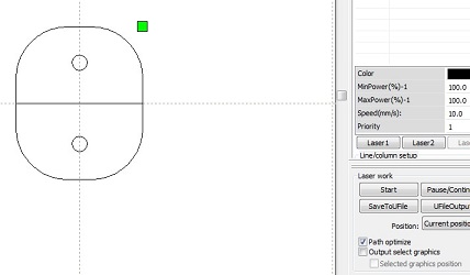
So i started with the testing. I cut some random links on the laser cutter and i cut the sheet using a cardboard. During testing we ealsied that we need to have the links in the same order put some data.
                        Link Lengths
                        4cm x 13cm
                        13cm x 9cm
                       all other links are taken as it is not mandatory to use them with spefic dimensions as it will depend on the motor we are using and the fasteners also.
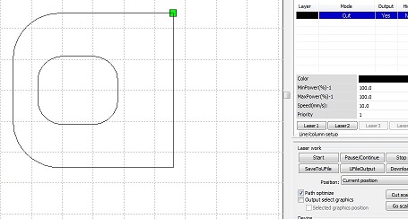
Since there was an entanglement in between the links so we had to design the liks again to seeif iot working properly or not.
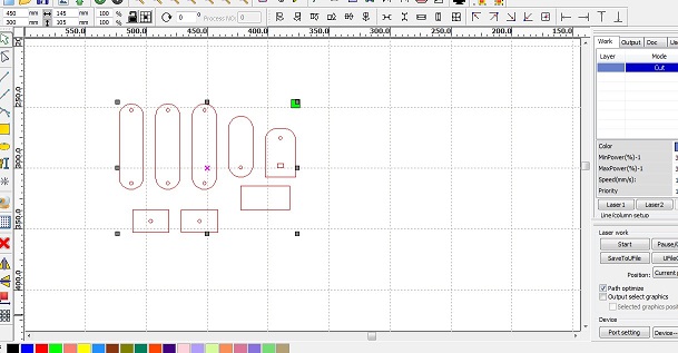
The links were then cut using that same dimensions and the motion of the bottle was achieved. I was so excited to see that because i was thinking that this motor is not going to be sufficient.
In the first trial the bottle knob was not geeting pushed and the side wall which was of a cardboard was also moving so all the force which should have transmittd to the bottle knob was not fully trasmiited.
In the second attempt, we increased the length form the base so that the knob is pushed. But since the base was not fixed so it was jot trasmitting the force properly.
In out third attempt, we achieved the required motion but then we also realised that the wall and the base should be hard and cardboard will not do in the lon run.
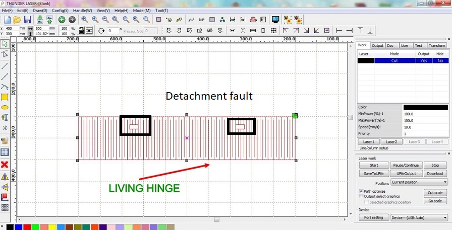
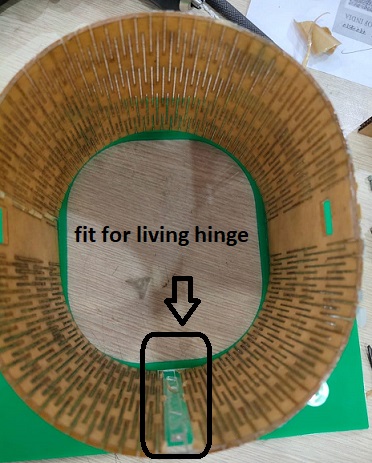
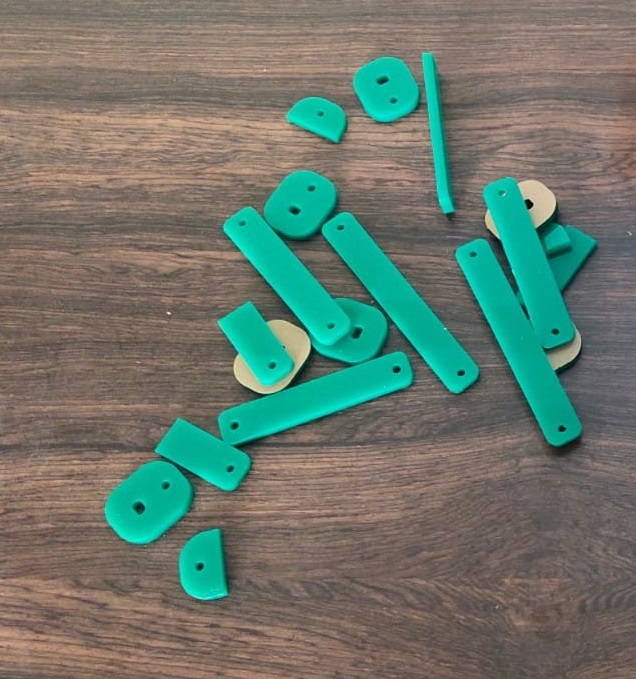
Now we have decided to make the overall structure of the machine using acrylic. I cut the links and the side wall using the acryl;ic sheet ut the center portion was circular in sahpe and i wanted to cut that circular shape using the acrylic only. so i thought of searching hoe to make cylinder using acrylic sheet and i found this video which helped me design the living hinge.
This page helped me to see the lot of applications of living hinges and the difefrent designs. I designed the living hinge in such a way that it combines at the end properly.
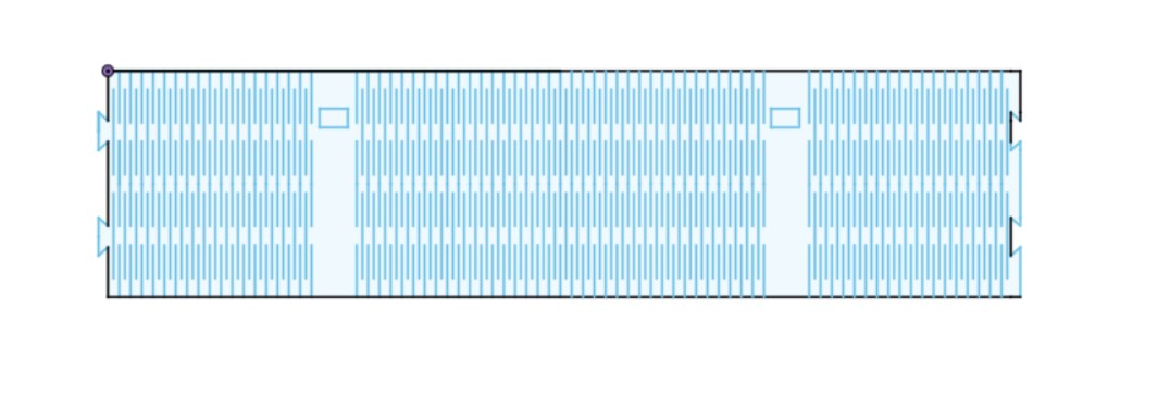
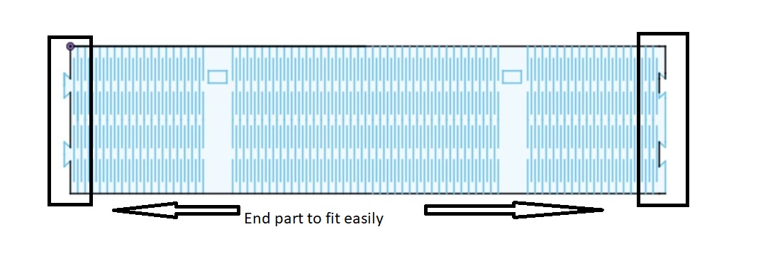
The part at the end made sure that it sticks to each other very easily.
To see the detailed info about the fabrication process, you can visit this page.
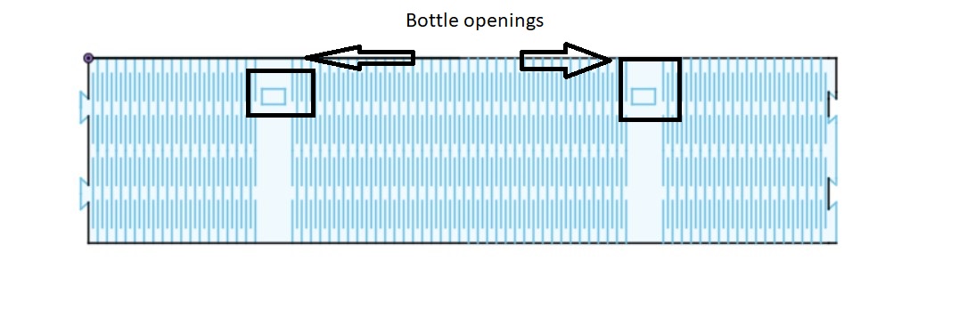
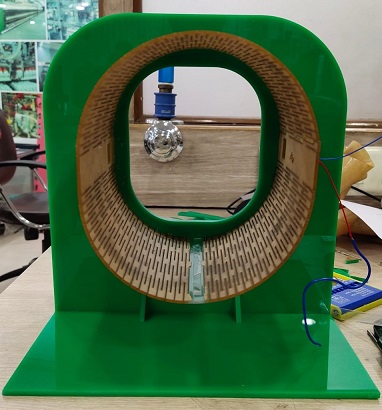
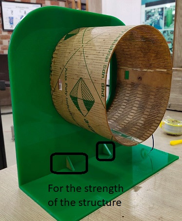
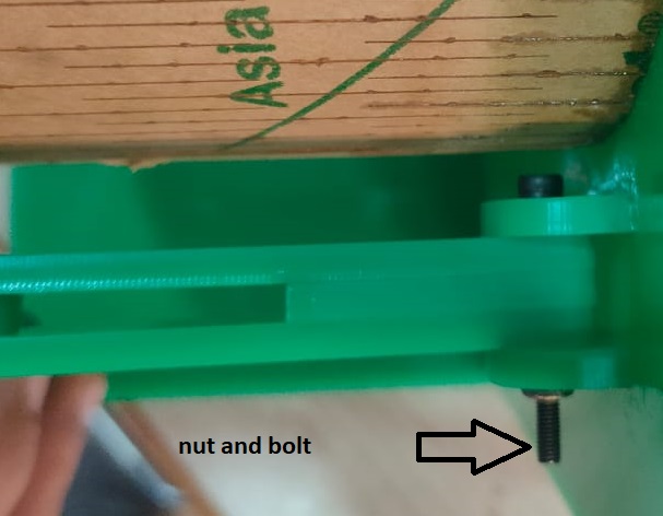
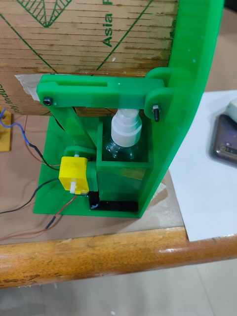
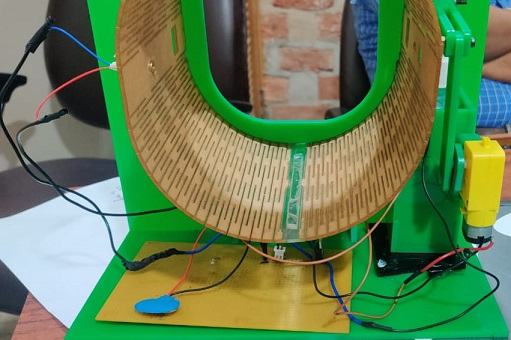
The living hinge in the first attempt got detached since the openings were also included in the same design but in the subsequent design this flow was removed. In the next attempt the hinge came in a single piece and it was converted into the cylinder. The end were also properly attached with the pressfit structure and with the help of the glue. The cylinder then was attached or glued to the side wall of the machine which is also made of the acrylic sheet. we have useda 3mm acrylic sheet for the outer body. Since with the movemnt of the motor , a force is transmitted to the side wall because of which it is required to give it strength. So i have glued two supports on the base which will resist its motion to the back side. We had seen this in our trial with the cardboard that there was a lot of movement of the side wall and from there i desided to instal, them in place. Now it was time to cut the links and come out with its working. So i decided to cut the links on acrylic itself since they have good strength and can transfer motion easily. The links were then connected to each other using the fasteners, we had to cut the length of the bolt to make sure that it does not come in the path of the links. This is how the link is attached to the motor shaft. A tight arrangement is necessary for the motion transfer to take place. this is stuck to the shaft by the use of the glue as well. The bottle is then put in a box which has to be stuck to the base so that it is positioned at one place only. In the trial i had found that the bottle was moving and because of which we did not get the required push so this time we have covered the bottle first with the cardboard and then with the acrylic.
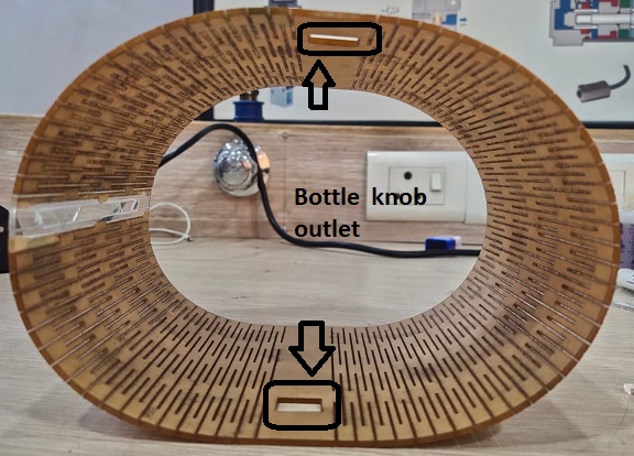
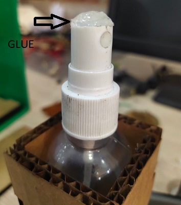
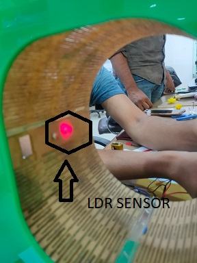
I had to put the extra glue on the surface just to make the surface protruding because the knob of the bottle was rotating and that was not required. We have drilled two holes in the living hinge (lsr and laser diode) has to be installd in the machine. LDR SENSOR SO it is time to install both the sensors to the cylinder and motor also and test the working of the machine. The motor was getting stuck on the base in between so we have to place one more surface to increase the length of the link. Well my target for this week is to create an electronic connection , in which when a person place his/her hand inside then the motor hould actuate and the persons hand will get sanitized , for this I opted for the most easiest
way like connectingeverything with arduino
Components i required
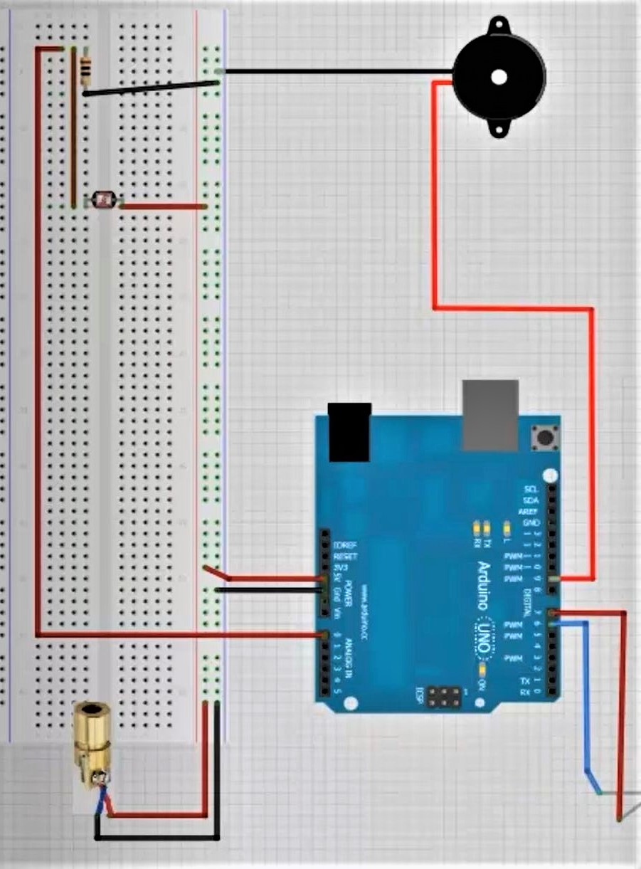
Connections should be made like this , you are require to connect VCC of Arduino to VCC same goes for GND also connect the GND of motor to the same point
After the connections are made you just rquire to upload the code which i have given below I am listing the code here in case you require to use the same code , just click and copy the code As i have given the pinout above you can see the connections are a piece of cake and the coding is also not that much of deal
Throught this video , you can see that my experiment worked This is the Bill of the material for the Electronics connection which i made using Arduino Well if we think the Plan A where we were using Arduino works well but We were asked by our college to make more of these sanitizers , so the previous option was not viable as for every machine using an arduino is too much
costly and making PCB Having an IC is also equivalent to this due to it also have good costs so i need to come up with another plan so i searched the arrangements which could be used in the current scenerio and i found the following circuit online.
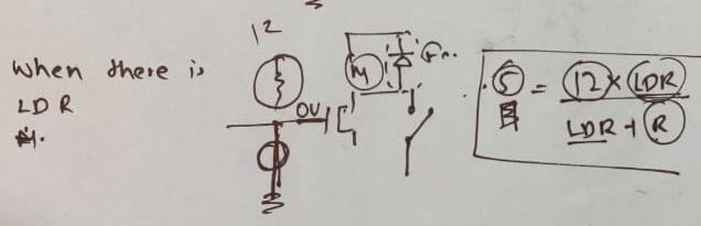
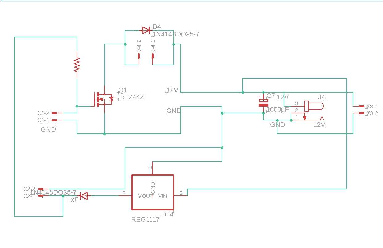
This is the circuit which we took as the reference for making our electronic circuit. Initially we were applying the circuit opposite to it where the circuit was behaving in an opposite manner. For ex, i wanted to run the motor when there is no light on the ldr from the laser diode but it was doing the opposite then we did some brainstorming in understanding the concept.The mistake we were doing was that we placed
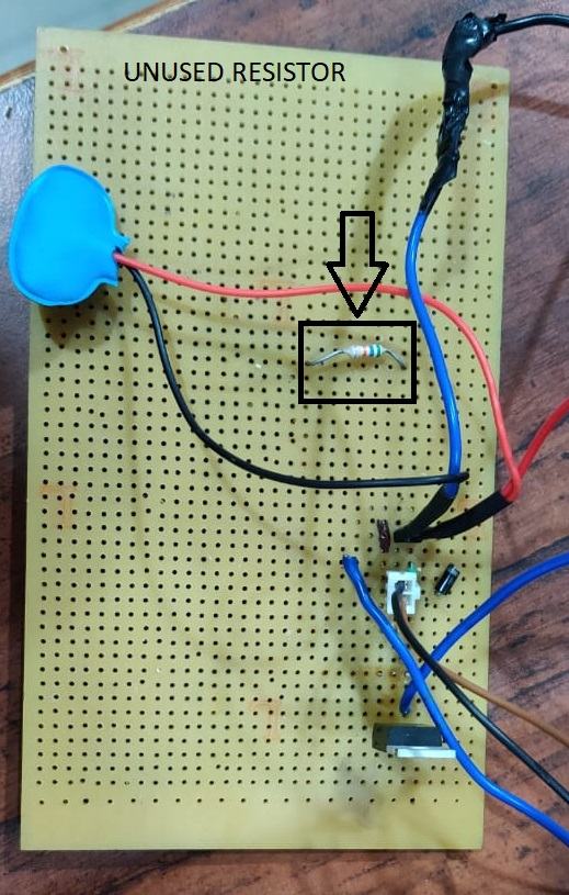
the ldr on the wrong position it has to be on the place where we added the resistor From the above circuit you will understand what i am trying to say , there are 2 case
i made the circuit such that when light falls on the ldr then the current does not reach the motor or the switch of the mosfet remains open. And when the light does not fall on it (for example the hand restricting the light
of the laser diode) the switch will be closed and the curent will go to the motor. We have also placed a Diode because of the Back EMF craeted in the DC motor. The diode will stop the current due to back emf to flow in the circuit. Initially we were using the 9volt battery but the discharge of the battery was at a very high pace so we thought of using the 12volt supply. Then we had to recalculate the resistor value and add that with the laser diode and
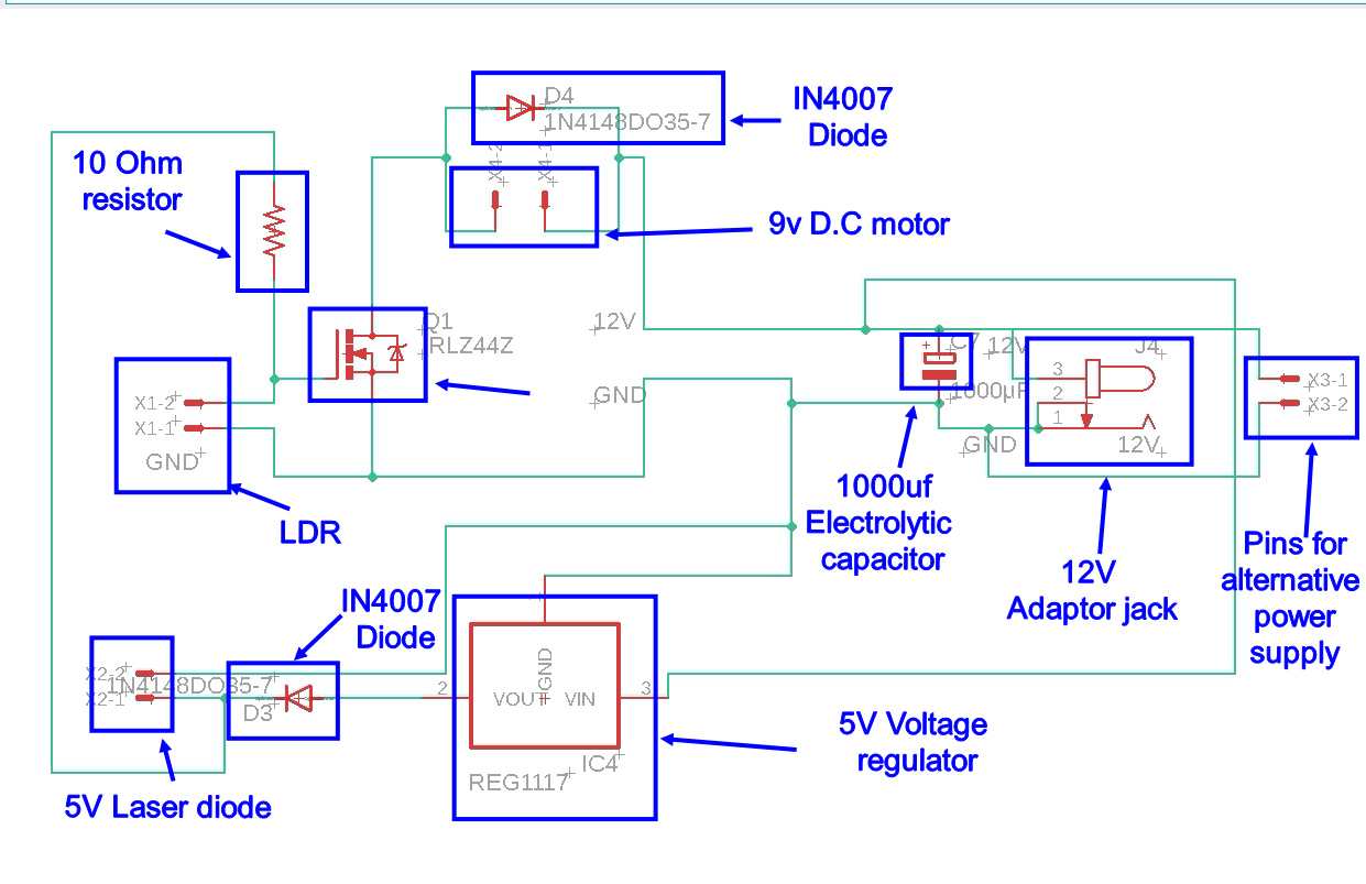
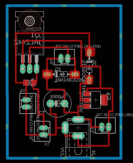
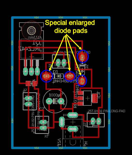
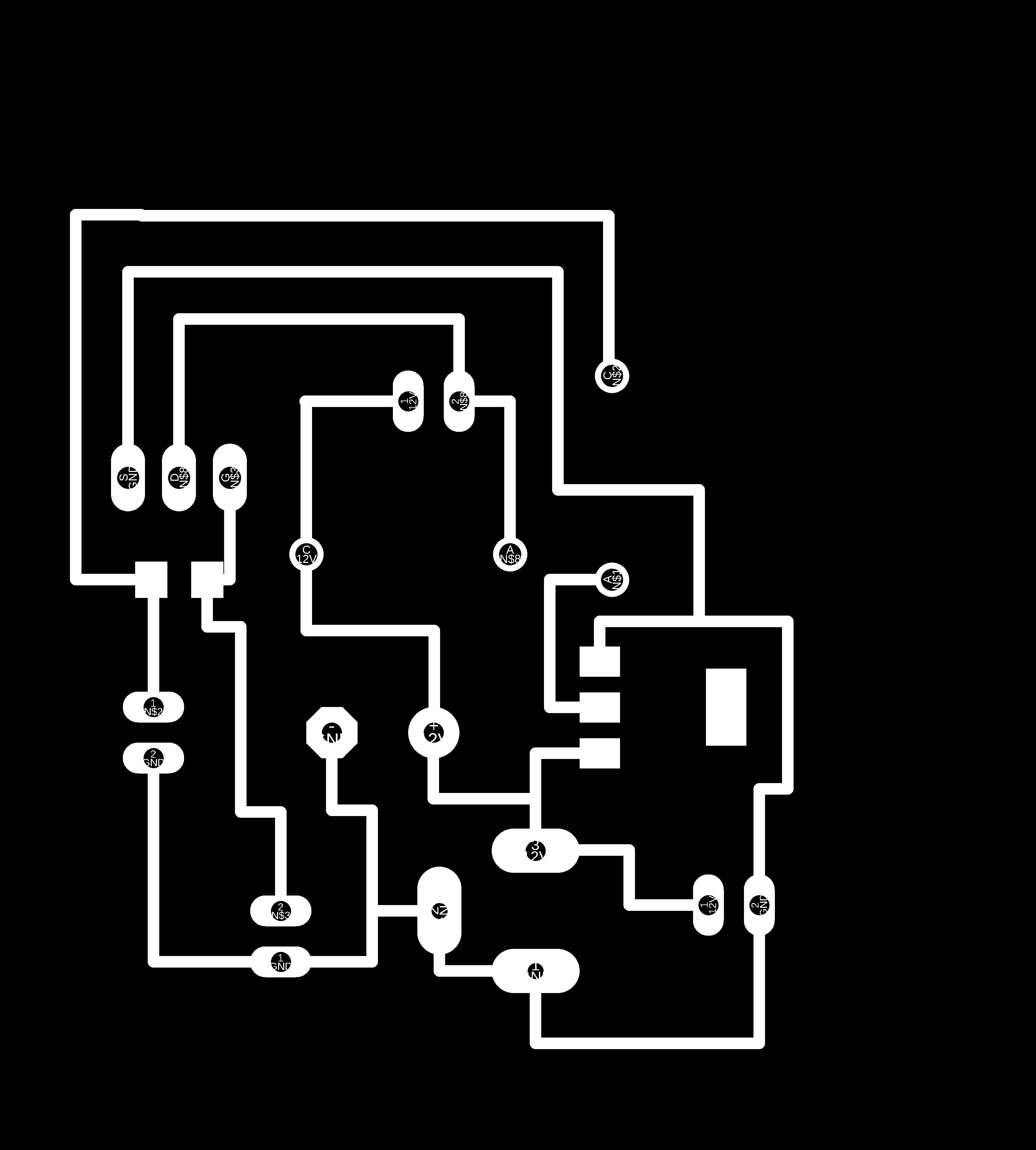
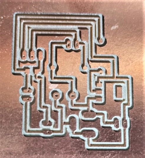
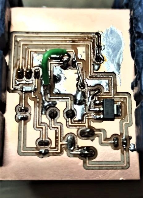
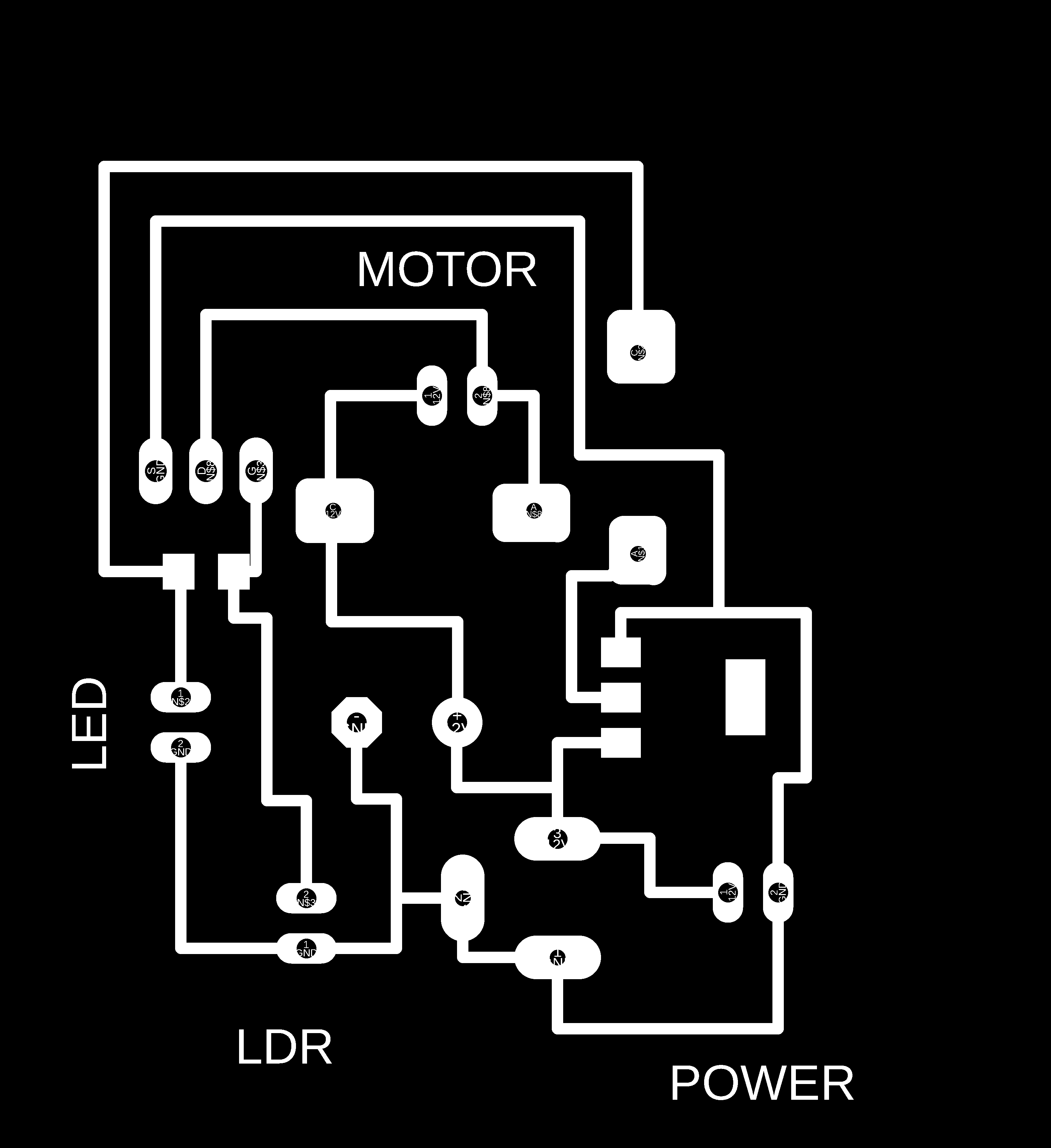
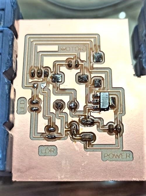
with the ldr. I added Ldr as well as I added Ldr as well as Light emiting diode to system This was our first test run It worked perfectly , now its time to make its PCB This will be my schematic for the pcb This is the list of components used by me for designing PCB This is the final design of board for the pcb And if you want to download the files for the pcb , by clicking on the link you can download the Eagle files, .rml files and PNG files as well You may wonder what are these blobs in the circuit , these are special altered pads , i was forced to make these for Diodes , as the conventional padding for diode were too thin and after making holes they were too fragile
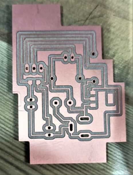
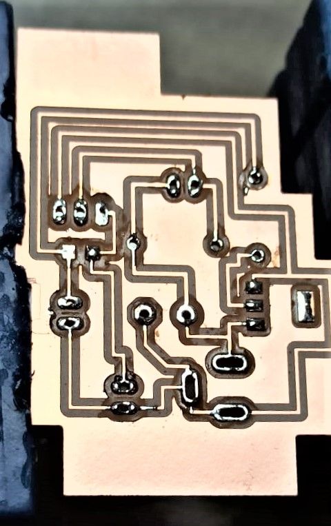
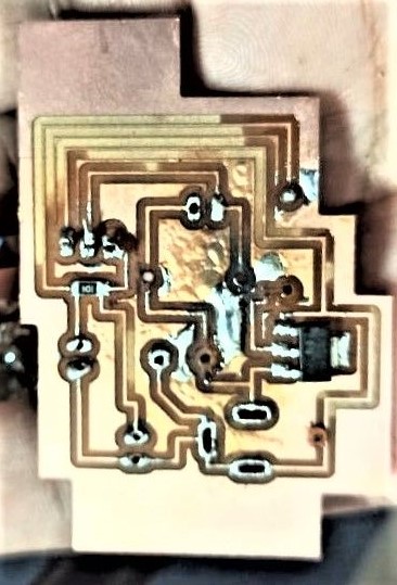
and broke very easily This is the png Image for the first PCB i made for sanitizer , as you can see the pads for diode are too thin , and when i soldered it , they came off and i was not able to work with it As you can see the size of track from this image that they are eally very thin This is the image before soldering the components , i used to add a little bit of solder before placing the components , which helps when adding all the components This is the image of failed pcb as diode tracks were removed , i have also de-solder the components so i can use it in next pcb Then to save the tracks i have incresed the track width from 16 mil to 24 mil , so the chance of track's ripping can be reduced In this pcb overall tracks are bigger but component pads like for diode remains same Again same thing happens due to less space on pads after hole the ,pads get rip off and now this is getting on my nerve so i designed a new pcb with more improvement. For this time i manually added added a thicker tracks for diode , so this problem doen't occur I think this is one of the best soldering i have done yet and the tracks didnt came out this time Well when we presented this project for Global evaluation , our Global Evaluator has pointed that , this project lacks Automation as there was not digital logic circuit , we were using an analogue circuit as it is good from
commerial point of view it is doen't qualify for this weeks evaluation criteria , so we decided to do something about this and tried to come up with an digital/ logic based circuit So meet the requirements of the evaluation we asdded an arduino to circuit and programmed it as well and this is the pin diagram for something similar to what we have done , this image and code were taken from instructables
site , if you like you can go on there website by clicking on this link
I am listing the code here in case you require to use the same code , just click and copy the code This is the code which we have taken from instructables and modify it according to our requirement like :
This video is all the testing our circuit using Arduino uno , and you can see it woks properly Time to test it with the whole machine This is the final video after proper packaging * "That project is fine for mechanism and actuation, but doesn't show automation. The automation component has to have some element of coordinating a sequence of activities; an analog circuit just connecting a sensor to a transistor
isn't adequate. Also, I expect to see a schematic and PCB design; they need to do better than soldering a perf board.
I am listing the code here in case you require to use the same code , just click and copy the code To control the despertion of Sanitising liquide , we added a Delay of 1.5sec for working of the motor and restricted the dispertion to 5 spray at a time . The machine will spray 5 times in 1.5 seconds and then it will detect
another hand and then it will again run for 1.5 seconds. We have provided delay 1500 when the motor is open and the delay of 3000 when the motor is closed.
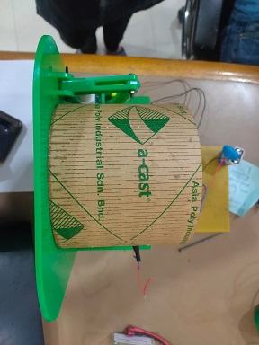
From this video you can see how the controlled dispertion is working This video is for the final video with all the packaging We have made the living hinge for the cylinder which is having slots in it because of which the santizer can fall on the electronic components placed beneath it. So it will be good to change it with some other material or arrangement.
We have installed only one bottle of sanitizer due to time constraint but it can be increased to two in future for higher effectiveness. We have covered the bottle with acrylic which is causing us the problem of refilling the bottle. In the modified design we can eliminate this constraint. It was a good experience working as a team for the machine as we explored a lot of options for the working of the machine. We managed to get it ready just before the time and to see the machine working the way we want it to
is very exciting to see. For all of us it will be a good experience if we want to continue to design and fabricate more machines in the future. Personally i will go with PLAN 2 as it is almost 3 times cheaper then PLAN 3 and 4 times cheaper than PLAN 1

Electronics
1. Arduino Uno board
2. A D.c motor
3. HC-SR04-Ultrasonic Range Finder
4. male female jumper wire
5. Breadboard
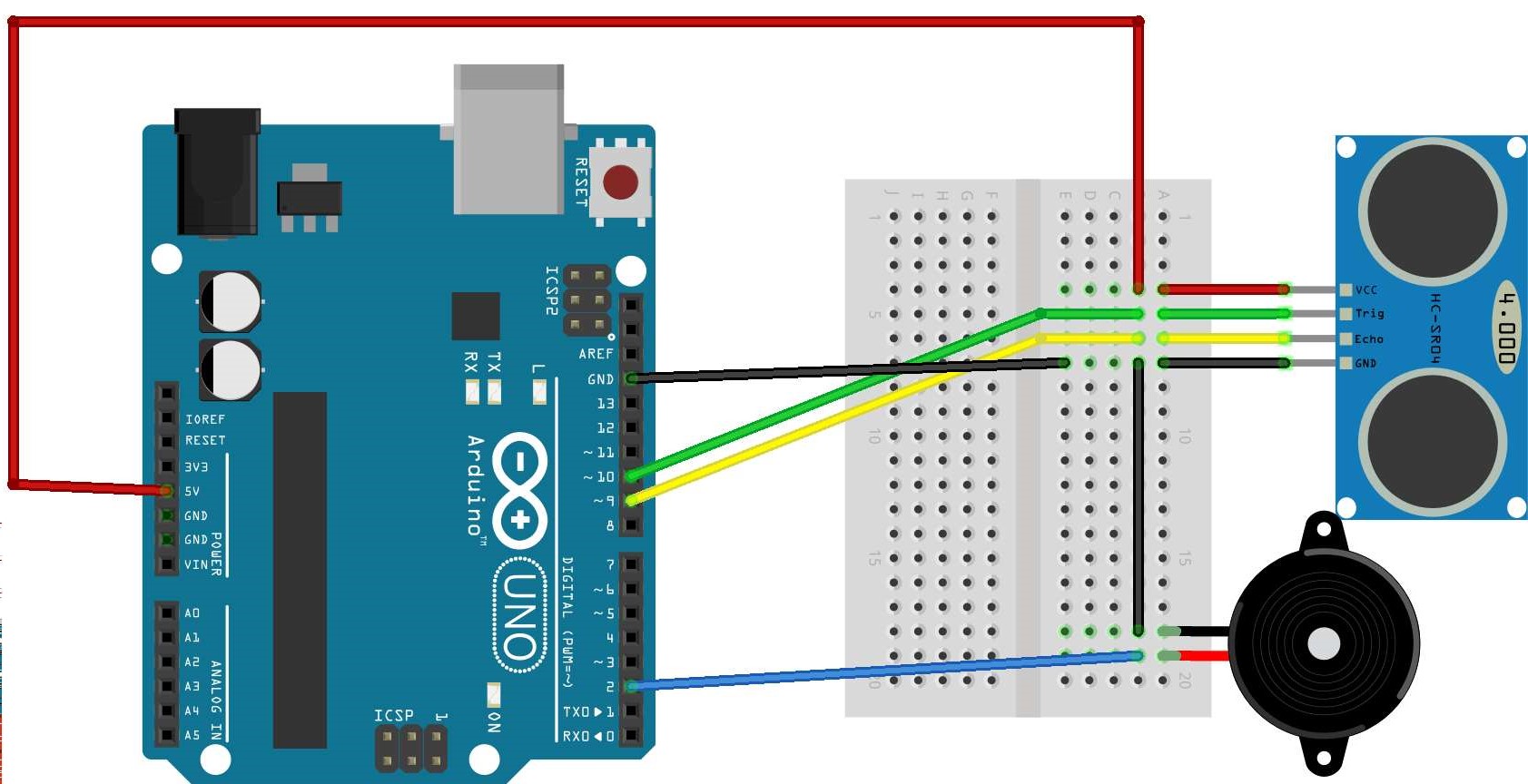
then connect PIN 12 to trig pin of sensor and pin 11 to echo pin of sensor and last not least connect Vcc pin of motor to PIN 2 of arduino ,its a PWM pin
int pinTrig = 12;   // connect the trigger pin of ultrasonic sensor -----> pin 12 .
int pinEcho = 11;    // connect the echo pin of ultrasonic sensor ---->  pin 11 .
int pinMotor = 2;    // connect the motor pin 2 .

long duration;

int distance;  // distance between object and ultrasonic sensor.

void setup() {


// put your setup code here, to run once:

Serial.begin(9600);

pinMode(pinTrig, OUTPUT);
pinMode(pinEcho, INPUT);
pinMode(pinMotor, OUTPUT);

}

void loop() {
// put your main code here, to run repeatedly:

digitalWrite(pinTrig, LOW);
delayMicroseconds(2);  // Delay for 2 Usec
digitalWrite(pinTrig, HIGH);
delayMicroseconds(10);    // Delay for 10 Usec


digitalWrite(pinTrig, LOW);
duration = pulseIn(pinEcho, HIGH);
distance = duration*0.034/2;

Serial.print("Distance:  ");
Serial.println(distance);


if(distance <= 18){   // the distance is in centimeter  you can set your value I select I select 18 because it my lucky number :)
digitalWrite(pinMotor, HIGH); // Start the motor


}else{

digitalWrite(pinMotor, LOW); // Stop the motor


}

}
Circuit explanantion
I have used the HC-SR04- Ultrasonic sensor for this circuit as it is a very easy to use sensor , it uses SONAR to determine the distance of an object just like the bats do. and have an impressive range of 2 cm to 400
cm
* This code implies that we defined the Trig pin of the sensor to pin 12 (Trigger pin is an Input pin. This pin has to be kept high for 10us to initialize measurement by sending US wave) and echo pin to pin 11 ( Echo
pin is an Output pin. This pin goes high for a period of time which will be equal to the time taken for the US wave to return back to the sensor.) and Motor pin to Pin 3
* so what basically happens is that my ultrasonic sensor is placed on the bread board and connected to my arduino and facing Horizonatally, when some obstacle comes across which is less than or equal to 18cm in this
direction the motor will start rotating. and the basic purpose is to start the actuation mechanism and spray disinfectant .
If you want to know more please click on this link , i learned to make this circuit from Arduino's Project hub page
Name
Description
Quantity
Price/Pcs
$
ARDUINO UNO R3
Will be the brain of my cicuit
1
Rs. 259
$3.50
HC-SR04- Ultrasonic sensor
For movement detection
1
Rs. 75
$1.01
9v D.c motor
For Actuatiion
1
Rs. 189
$2.56
Jumper wires
For connections
2
Rs. 55
$0.71
Total
Rs. 578
$7.78
Plan 2
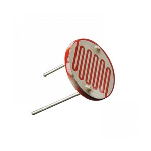
It worked on the basic principle of LDR sensor i.e.When there is no light on the ldr sensor its resistance can reach to 2-3 Million Ohms and no current can pass through it and when light emits resistance reduces drastically
to few kilo ohms depending ont the intensity of Light

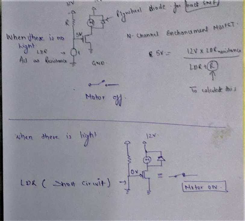
1. When there is no light
2. when there is light
Name of components
Quantity
LDR Sensor
1
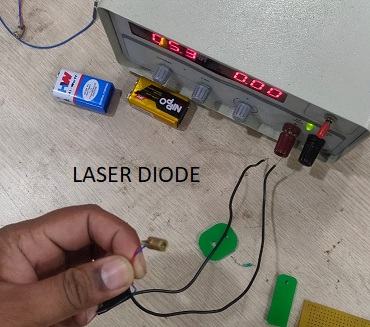
5V Laser diode
1
9v D.c motor
1
IRFZ44N N-channel mosfet
1
360K Ohm resistor
1
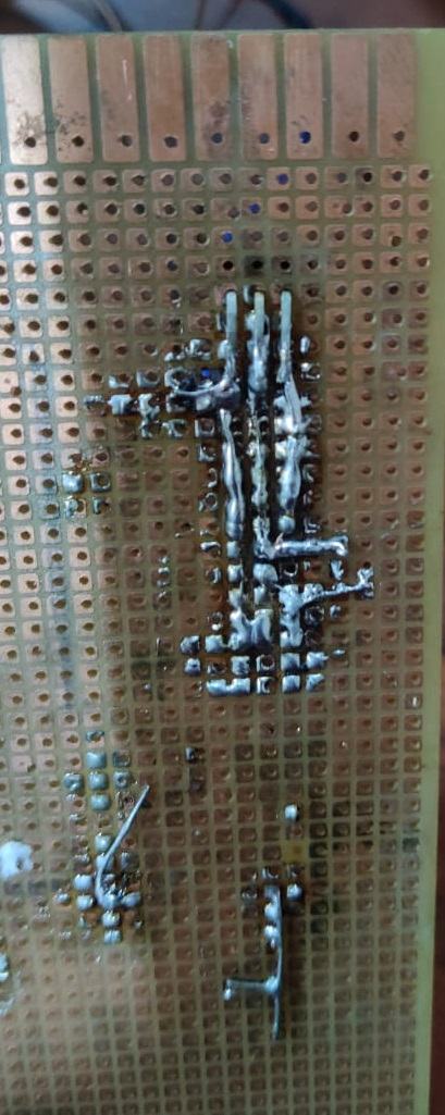
This is the soldering which we have done to connect the components to get the required functionality only to verify our concept that why i used perforated board and if it works i planned to make PCB later.
FAB SANITIZER MARK 1 PCB
Name
Description
Quantity
Price/Pcs
$
LDR Sensor
will be the main input device and also act as a million ohm resistor when no light is there
1
Rs. 5
$0.068
5V Laser diode
Act as a light source and also act as a trigger
1
Rs. 20
$0.27
9v D.c motor
For Actuatiion
1
Rs. 45
$0.61
IRFZ44N N-channel mosfet
Will act as a Gate for this analogue circuit
1
Rs. 20
$0.27
10K Ohm resistor
For safety of LDR
1
Rs. 3
$0.041
IN4007 diode 1A 1000V
To control back emf
2
Rs. 10
$0.14
5V REG1117 Voltage Regulator
To reduce 12V to 5V
1
Rs. 7
$0.10
2 X 1 JST Male Header Pin
To connect different components
4
Rs. 8
$0.11
12V D.C Female power jack
To connect 12V adaptor to it
1
Rs. 10
$0.14
Total
Rs. 128
$1.73
FAB SANITIZER PCB MARK 1

FAB SANITIZER PCB MARK 1.1
FAB SANITIZER PCB MARK 1.2
Plan 3
                    int sensorPin=A0;
                    int sensorValue=0;

                    int motorPin=10;

                    void setup() {
                    Serial.begin(9600);
                    pinMode(sensorPin,INPUT);
                    pinMode(motorPin,OUTPUT);
                    }

                    void loop() {

                    sensorValue=analogRead(sensorPin);

                    if(sensorValue<=600)

                    {
                    digitalWrite(motorPin,HIGH);
                    }
                     else {
                    digitalWrite(motorPin,LOW);
                    }
                    Serial.println(SensorValue);
                    }
* Removed the leds which were initially installed in the circuit.
* Changed the buzzer with motor
Some improvements
* "It would be adequate if they added a control loop, with a processor setting the duration of dispensing the sanitizer, as commercial units do."
These were some comments which were given to us by our Prof. Neil Gershenfeld , so we have worked on all the points except second one , so we work on the second point and is given here
                                int sensorPin=A0;
                                int sensorValue=0;

                                int motorPin=10;

                                void setup() {
                                Serial.begin(9600);
                                pinMode(sensorPin,INPUT);
                                pinMode(motorPin,OUTPUT);
                                }

                                void loop() {

                                sensorValue=analogRead(sensorPin);
                                Serial.println(sensorValue);
                                if(sensorValue<=10)

                                {
                                digitalWrite(motorPin,HIGH);
                                delay(1500);     // motor remians open for 1.5 seconds
                                digitalWrite(motorPin,LOW);
                                delay(3000);     // motor remians open for 3 seconds

                                }
                                 else {
                                digitalWrite(motorPin,LOW);
                                }

                                }
If the hand remains in the hole for more than 4.5 seconds then the motor will start again but the chances of happening that is very less.
Name
Description
Quantity
Price/Pcs
$
ARDUINO UNO R3
Will be the main brain of this system
1
Rs. 259
$3.50
LDR Sensor
will be the main input device and also act as a million ohm resistor when no light is there
1
Rs. 5
$0.068
5V Laser diode
Act as a light source and also act as a trigger
1
Rs. 20
$0.27
9v D.c motor
For Actuatiion
1
Rs. 45
$0.61
10K Ohm resistor
For safety of LDR
1
Rs. 3
$0.041
IN4007 diode 1A 1000V
To control back emf
1
Rs. 5
$0.07
Total
Rs. 337
$4.45
Future Development oppurtunities
Conclusion


