Input devices (WEEK 10)
Individual Assignment:
- Measure something: add a sensor to a microcontroller board. that you have designed and read it.
Group Assignment:
- Probe an input device's analog levels and digital signals.
IMPORTANT NOTE : ALL OF MY IMAGES ARE POP UP IMAGES , IF YOU HAVE ANY PROBLEM READINGS THOSE IMAGES , PLEASE CLICK ON THEM AND THEY WILL ENLARGE AUTOMATICALLY AND YOU CAN READ THEM EASILY
INPUT DEVICES
An input device responds to changes in the environment and produces a suitable electrical signal for processing in an electronic circuit.
In all input devices, other forms of energy are transformed into electrical energy.
Below are some common input devices with examples of how they might be used.
Microphone

Microphone circuit symbol: a circle next to a straight vertical line. A microphone generates a voltage when sound reaches it. It is used in a telephone or an intercom.
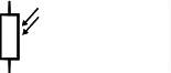
Thermistor

Themistor circuit symbol: a vertical line broken by a long rectangle with a diagonal line through it. One end of the diagonal line has an extra portion angled off, parallel to the vertical line. Its resistance increases when the temperature falls. Is used as a sensor in heating systems.
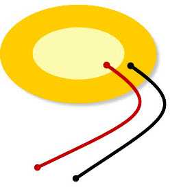
Solar cell or photo-voltaic cell

Solar cell circuit symbol: a horiontal line broken by a pair of vertical lines, the left slightly taller than the right. Two short parallel arrows point towards it from the top right. Produces a voltage when light falls on it, provides energy for satellites.
Light dependent resistor (LDR)
Light-dependent resistor circuit symbol: a vertical line broken by a long rectangle. Two short parallel arrows point towards it from the top right. Resistance decreases as light level rises. Used to control street lights.
Capacitor

Electrical symbol for a capacitor - a vertical line parallel to another vertical line Used in timing circuits and electronic amplifiers.
Switch

Switch circuit symbol: a horizontal line with a circle on its right end; a line attached to this circle at 45 degrees; a circle below this is attached to a horizontal line extending to the right. Allows current in a circuit when closed. Used to switch on circuits.
Voltage divider
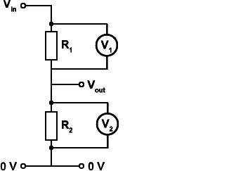
Voltage divider circuit diagram: 2 resistors,R1 and R2,connected vertically,each with a voltmeter,V1 and V2.Top of circuit is labelled V in, bottom is 0 V, branch between two resistors labelled V out. To create a voltage across the bottom component that can then be sent to a process device. Used in devices, eg mosfets or npn transistors, where a voltage change switches on or off a circuit. Analogue Sensors Analogue
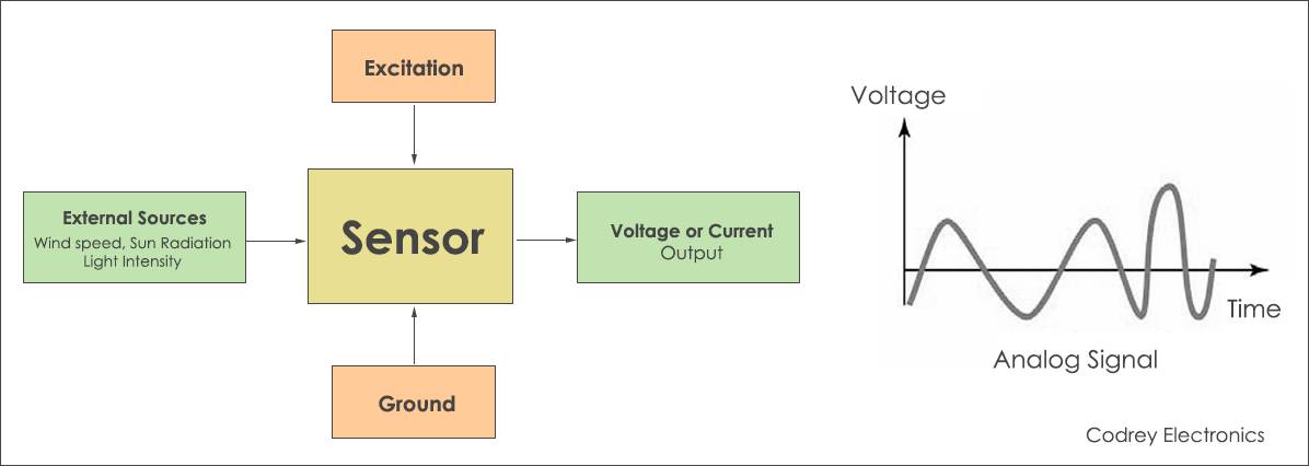
Analogue Sensors
produce a continuous output signal or voltage which is generally proportional to the quantity being measured. Physical quantities such as Temperature, Speed, Pressure, Displacement, Strain etc are all analogue quantities as they tend to be continuous in nature.
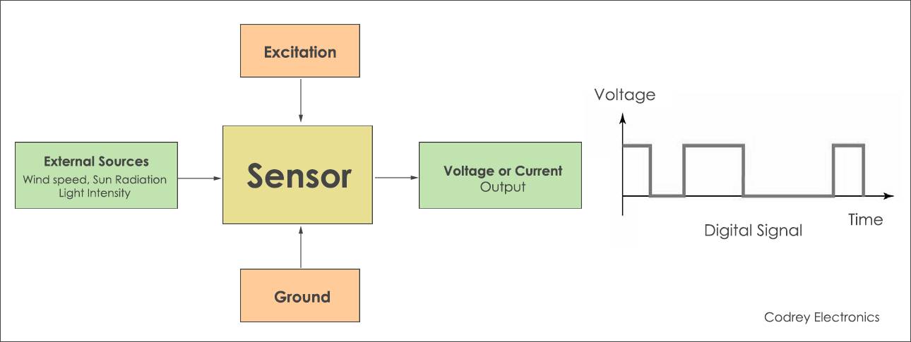
Digital Sensors
A digital sensor is an electronic or electrochemical sensor, where data is digitally converted and transmitted. Sensors are often used for analytical measurements, e.g. the measurement of chemical and physical properties
of liquids. Typical measured parameters are pH value, conductivity, oxygen, redox potentials, and others. Such measurements are used in the industrialized world and give vital input for process control.
Sensors of analogue type were used in the past, but today more and more digital sensors are used. This article describes the difference between them and discusses the reason for the development of digital
sensors.
SOME BASIC SENSORS
Accelerometers
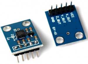
Analog sensors that detect changes in position, velocity, orientation, shock, vibration, and tilt by sensing motion are called as accelerometers. These analog accelerometers are again classified into different types
based on the variety of configurations and sensitivities.
These accelerometers are available as analog and digital sensors, based on the output signal. Analog accelerometer produces a constant variable voltage based on the amount of acceleration applied to the
accelerometer.
Light Sensors
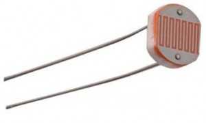
Analog sensors that are used for detecting the amount of light striking the sensors are called as light sensors. These analog light sensors are again classified into various types such as photo-resistor, Cadmium Sulfide (CdS), and, photocell. Light dependent resistor (LDR) can be used as analog light sensor which can be used to switch on and off loads automatically based on the day light incident on the LDR. The resistance of the LDR increases with decrease in light and decreases with increase in light.
Sound Sensors
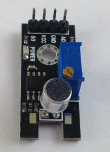
Analog sensors that are used to sense sound level are called as sound sensors. These analog sound sensors translate the amplitude of the acoustic volume of the sound into an electrical voltage for sensing sound level. This process requires some circuitry, and utilizes microcontroller along with a microphone for creating an analog output signal.
Pressure Sensor
The analog sensors that are used to measure the amount of pressure applied to a sensor are called as analog pressure sensors. Pressure sensor will produce an analog output signal that is proportional to the amount of applied pressure. These pressure sensors are used for different types of applications such as piezoelectric plates or piezoelectric sensors that are used for the generation of electric charge. These piezoelectric sensors are one type of pressure sensors that can produce an analog output voltage signal proportional to the pressure applied to the piezoelectric sensor.
Individual Assignment:
For this week the individual task was to make a pcb for an input device , which you may or may not use for the final project
The sensor which i used for this week is a specialized input sensor i.e. PMS 7003 ppm sensor
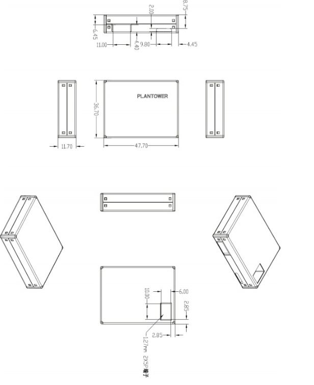
PLANTOWER Laser PM2.5 DUST SENSOR PMS7003 High-precision laser dust concentration sensor digital dust particles G7
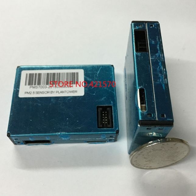
PMS7003 is a kind of digital and universal particle concentration sensor , which can be used to obtain the number of suspended particles in the air , i.e. the concenteration of particles and output them in the form of didital interface . this sensor can be inserted into variable instrument related to the cocentration of suspended in the air or other environmental improvement equipements to provide correct concenteration data in time.
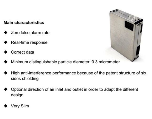
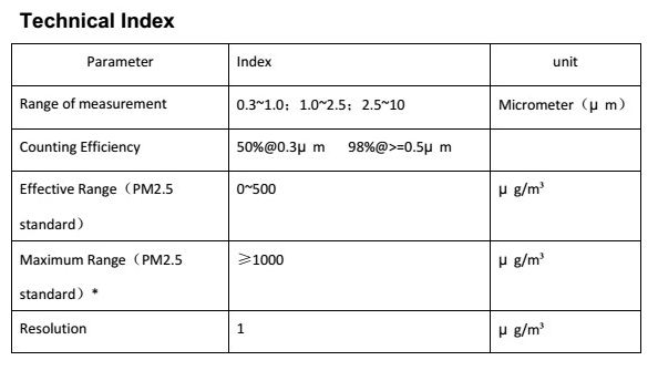
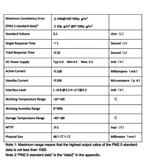
I am listing the technical deatil of this sensor and if you would like to know more about this sensor please click on this link and this will guide you to the componies official site
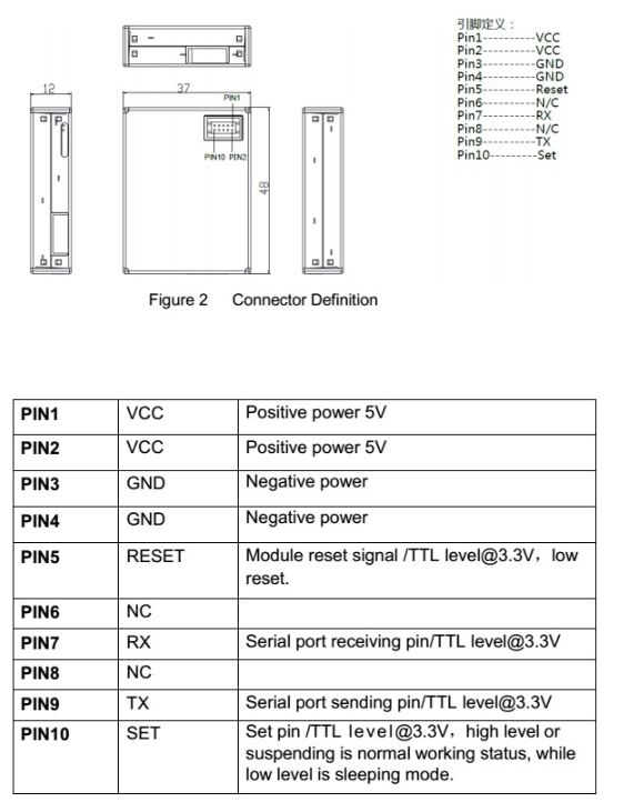
Wiring with the Arduino
Before starting up please click on this page to know more about integeration of PPM sensor
his site was very helpull because there are not many information about this sensor on net
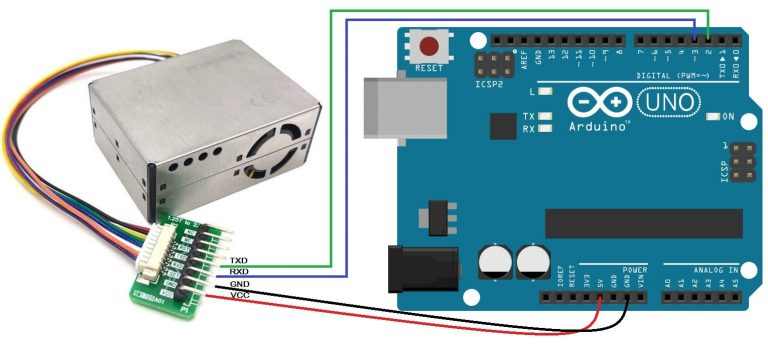
I am rewuired to connect RX-TX from my arduino to sensor and then provide VCC AND GND pin
well for this i required to give software serial , as software serial is simply a way of defining digital ports of board to work as RX=TX
As i explained above i have connected VCC of sensor to VCC OF arduino and GND of to GND , and made PIN 2, PIN 3 my software serial. and uploaded the code
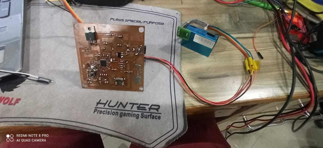
Connecting sensor to my FAB FILTER ISP
For my final project i have made this PCB , if you want to know more about this you can click on this link and you will be guided to my final page where i have documented its making
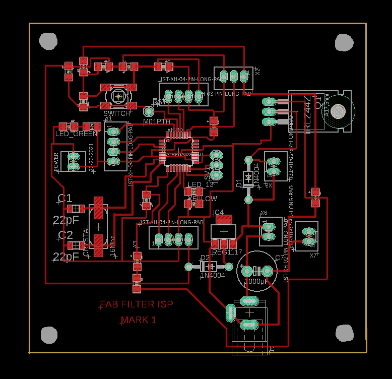
This is my board
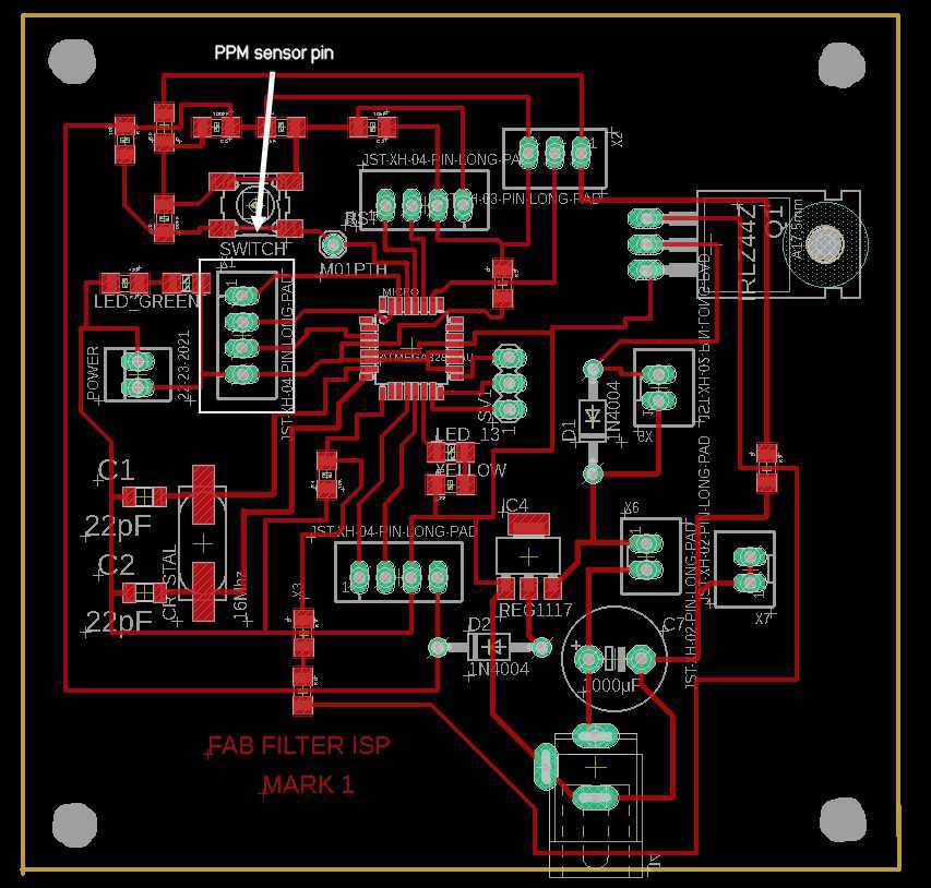
These pins are for PPM sensor , i have made specially , having 1 VCC , 1 GND and PIN 2 AND PIN 3 as software serial
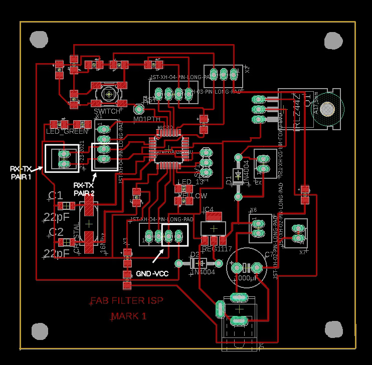
Plus i made 2 pairs of RX-TX to do networking from the same pins you can click on this link to know more about it
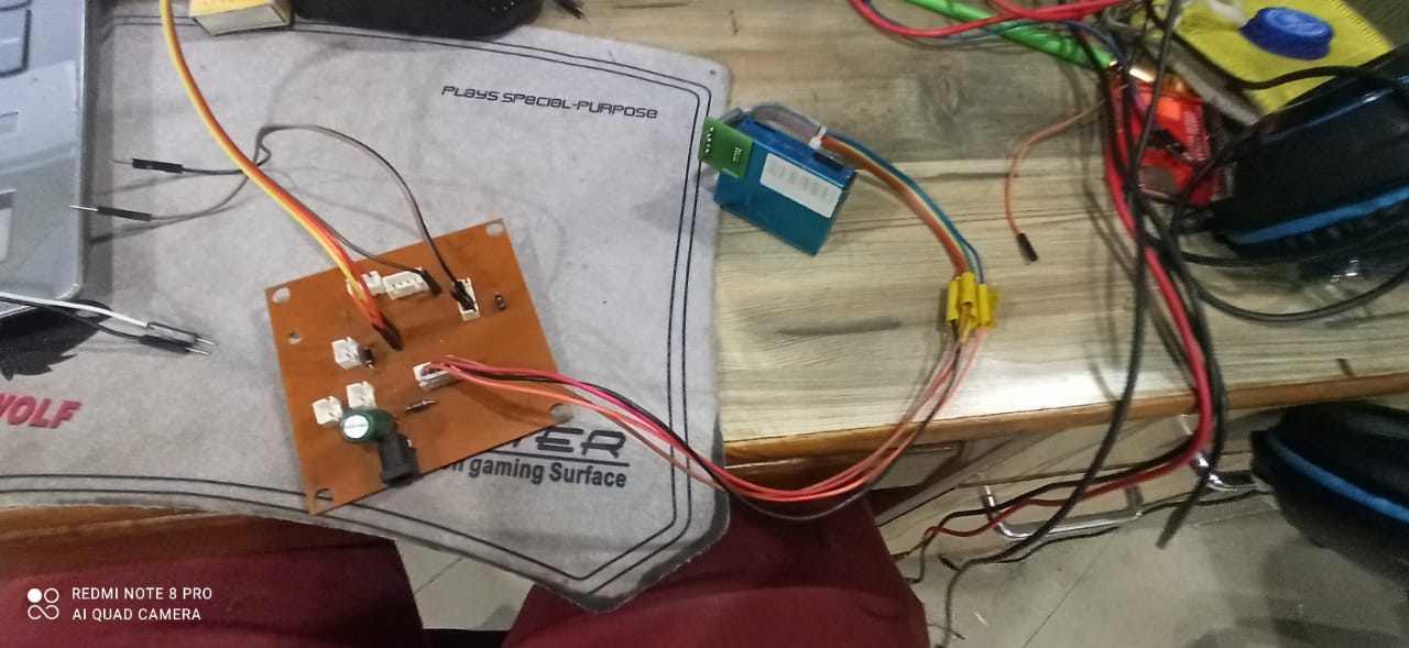
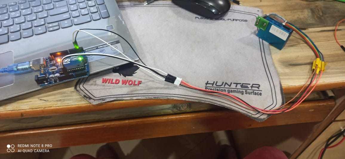
I made the connections
Time to test it using my custom board
In this video i am explaining the connectionsand showing that this works
#include "SoftwareSerial.h"
SoftwareSerial pmsSerial(2, 3);

void setup() {
// our debugging output
Serial.begin(115200);

// sensor baud rate is 9600
  pmsSerial.begin(9600);
 }

struct pms5003data {
uint16_t framelen;
uint16_t pm10_standard, pm25_standard, pm100_standard;
uint16_t pm10_env, pm25_env, pm100_env;
uint16_t particles_03um, particles_05um, particles_10um, particles_25um, particles_50um, particles_100um;
uint16_t unused;
uint16_t checksum;
};

struct pms5003data data;

void loop() {
if (readPMSdata(&pmsSerial)) {
// reading data was successful!
 Serial.println();
Serial.println("---------------------------------------");
Serial.println("Concentration Units (standard)");
Serial.print("PM 1.0: "); Serial.print(data.pm10_standard);
Serial.print("\t\tPM 2.5: "); Serial.print(data.pm25_standard);
Serial.print("\t\tPM 10: "); Serial.println(data.pm100_standard);
Serial.println("---------------------------------------");
Serial.println("Concentration Units (environmental)");
Serial.print("PM 1.0: "); Serial.print(data.pm10_env);
Serial.print("\t\tPM 2.5: "); Serial.print(data.pm25_env);
Serial.print("\t\tPM 10: "); Serial.println(data.pm100_env);
Serial.println("---------------------------------------");
Serial.print("Particles > 0.3um / 0.1L air:"); Serial.println(data.particles_03um);
Serial.print("Particles > 0.5um / 0.1L air:"); Serial.println(data.particles_05um);
Serial.print("Particles > 1.0um / 0.1L air:"); Serial.println(data.particles_10um);
Serial.print("Particles > 2.5um / 0.1L air:"); Serial.println(data.particles_25um);
Serial.print("Particles > 5.0um / 0.1L air:"); Serial.println(data.particles_50um);
Serial.print("Particles > 10.0 um / 0.1L air:"); Serial.println(data.particles_100um);
Serial.println("---------------------------------------");
}
}

boolean readPMSdata(Stream *s) {
if (! s->available()) {
return false;
}

// Read a byte at a time until we get to the special '0x42' start-byte
if (s->peek() != 0x42) {
s->read();
return false;
}

// Now read all 32 bytes
if (s->available() < 32) {
return false;
}

uint8_t buffer[32];
uint16_t sum = 0;
s->readBytes(buffer, 32);

// get checksum ready
for (uint8_t i=0; i<30; i++) {
sum += buffer[i];
}

/* debugging
for (uint8_t i=2; i<32; i++) {
Serial.print("0x"); Serial.print(buffer[i], HEX); Serial.print(", ");
}
Serial.println();
*/

// The data comes in endian'd, this solves it so it works on all platforms
uint16_t buffer_u16[15];
for (uint8_t i=0; i<15; i++) {
buffer_u16[i] = buffer[2 + i*2 + 1];
buffer_u16[i] += (buffer[2 + i*2] << 8);
}

// put it into a nice struct :)
 memcpy((void *)&data, (void *)buffer_u16, 30);

if (sum != data.checksum) {
Serial.println("Checksum failure");
return false;
}
// success!
return true;
}
This is the original program for the PMS7003 sensor
you can use this code by just clicking and copying it
And if you want to download the CODE ,you can click on this link for that
PMS7003_ProgramOr if youu want to know more about the code and sensor click on this link
Modified CODE
Well this sensor can detect particle of variose sizes ranging from 0.3um to 10um , which include 9 different values but i required only 3 i.e. PM 1.0 ,PM 2.5 , PM 10 , plus the sensor also has a option of displaying standord as well as enviroment value for each of the 3 values and i only required enviroment values . So this prompt me to modify the code according to my requirement.
#include "SoftwareSerial.h"
SoftwareSerial pmsSerial(2, 3);

void setup() {
// our debugging output
Serial.begin(115200);

// sensor baud rate is 9600
pmsSerial.begin(9600);
}

struct pms5003data {
uint16_t framelen;
uint16_t pm10_standard, pm25_standard, pm100_standard;
uint16_t pm10_env, pm25_env, pm100_env;
uint16_t particles_03um, particles_05um, particles_10um, particles_25um, particles_50um, particles_100um;
uint16_t unused;
uint16_t checksum;
};

struct pms5003data data;

void loop() {
if (readPMSdata(&pmsSerial)) {
// reading data was successful!
Serial.println();

Serial.println("---------------------------------------");
Serial.println("Concentration Units (environmental)");
Serial.print("PM 1.0: "); Serial.print(data.pm10_env);
Serial.print("\t\tPM 2.5: "); Serial.print(data.pm25_env);
Serial.print("\t\tPM 10: "); Serial.println(data.pm100_env);
Serial.println("---------------------------------------");

}
}

boolean readPMSdata(Stream *s) {
if (! s->available()) {
return false;
}

// Read a byte at a time until we get to the special '0x42' start-byte
if (s->peek() != 0x42) {
s->read();
return false;
}

// Now read all 32 bytes
if (s->available() < 32) {
return false;
}

uint8_t buffer[32];
uint16_t sum = 0;
s->readBytes(buffer, 32);

// get checksum ready
for (uint8_t i=0; i<30; i++) {
sum += buffer[i];
}

/* debugging
for (uint8_t i=2; i<32; i++) {
Serial.print("0x"); Serial.print(buffer[i], HEX); Serial.print(", ");
}
Serial.println();
*/

// The data comes in endian'd, this solves it so it works on all platforms
uint16_t buffer_u16[15];
for (uint8_t i=0; i<15; i++) {
buffer_u16[i] = buffer[2 + i*2 + 1];
buffer_u16[i] += (buffer[2 + i*2] << 8);
}

// put it into a nice struct :)
memcpy((void *)&data, (void *)buffer_u16, 30);

 if (sum != data.checksum) {
Serial.println("Checksum failure");
return false;
}
// success!
return true;
}
And if you want to download the CODE ,you can click on this link for that
PMS7003_Modified_ProgramGroup Assignment:
Measuring Analog Signal:
We measured the analog signal by connecting both the probe of oscilloscope to Gnd and Vcc pin of dc motor and rotated the shaft manually. The motor is generally consisdered as the output device but if we give rotation to motor manually then an induced voltage can be seen on the oscilloscope. Since the construction of the motor and generator are similar so we used motor as the input device.
Measuring Digital Signal:
We uploaded Blink code on the UNO board and we observed the pulse signal.Above are the results for the same.