Networking and communications (WEEK 15)
Individual Assignment:
Design, build, and connect wired or wireless node(s) with network or bus addresses
Group Assignment:
Send a message between two projects
IMPORTANT NOTE : ALL OF MY IMAGES ARE POP UP IMAGES , IF YOU HAVE ANY PROBLEM READINGS THOSE IMAGES , PLEASE CLICK ON THEM AND THEY WILL ENLARGE AUTOMATICALLY AND YOU CAN READ THEM EASILY
Introduction
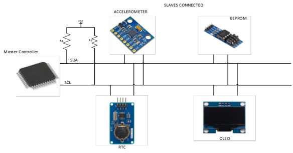
I2C PROTOCOL
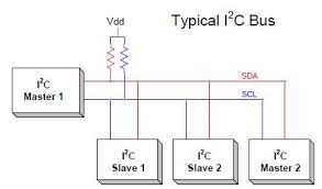
This image was taken from Circuitdigest.com and if you like to download it or know more about I2C bus Protocol please click on this link
I2C stands for inter integrated circuit. I2C requires only two wires connecting all peripherals to microcontroller.I2C requires two wires SDA (serial data line) and SCL (serial clock line) to carry information between devices. It is a master to slave communication protocol. Each slave has a unique address. Master device sends the address of the target slave device and read/write flag. The address is match any slave device that device is ON, remaining slave devices are disable mode. Once the address is match communication proceed between master and that slave device and transmitting and receiving the data.
SPI Protocol
SPI stands for serial peripheral interface. It is one of the serial communication protocol developed by Motorola. Some times SPI protocol is also called a 4-wire protocol. It requires four wires MOSI, MISO, SS, and SCLK.SPI protocol used to communicate the master and slave devices. The master first configures the clock using a frequency. The master then selects the particular slave device for communication by pulling the chip select button. That particular device is selected and starts the communication between master and that particular slave. The master select only one slave at a time. It is full duplex communication protocol. Not limited to 8 bit words in the case of bit transferring.
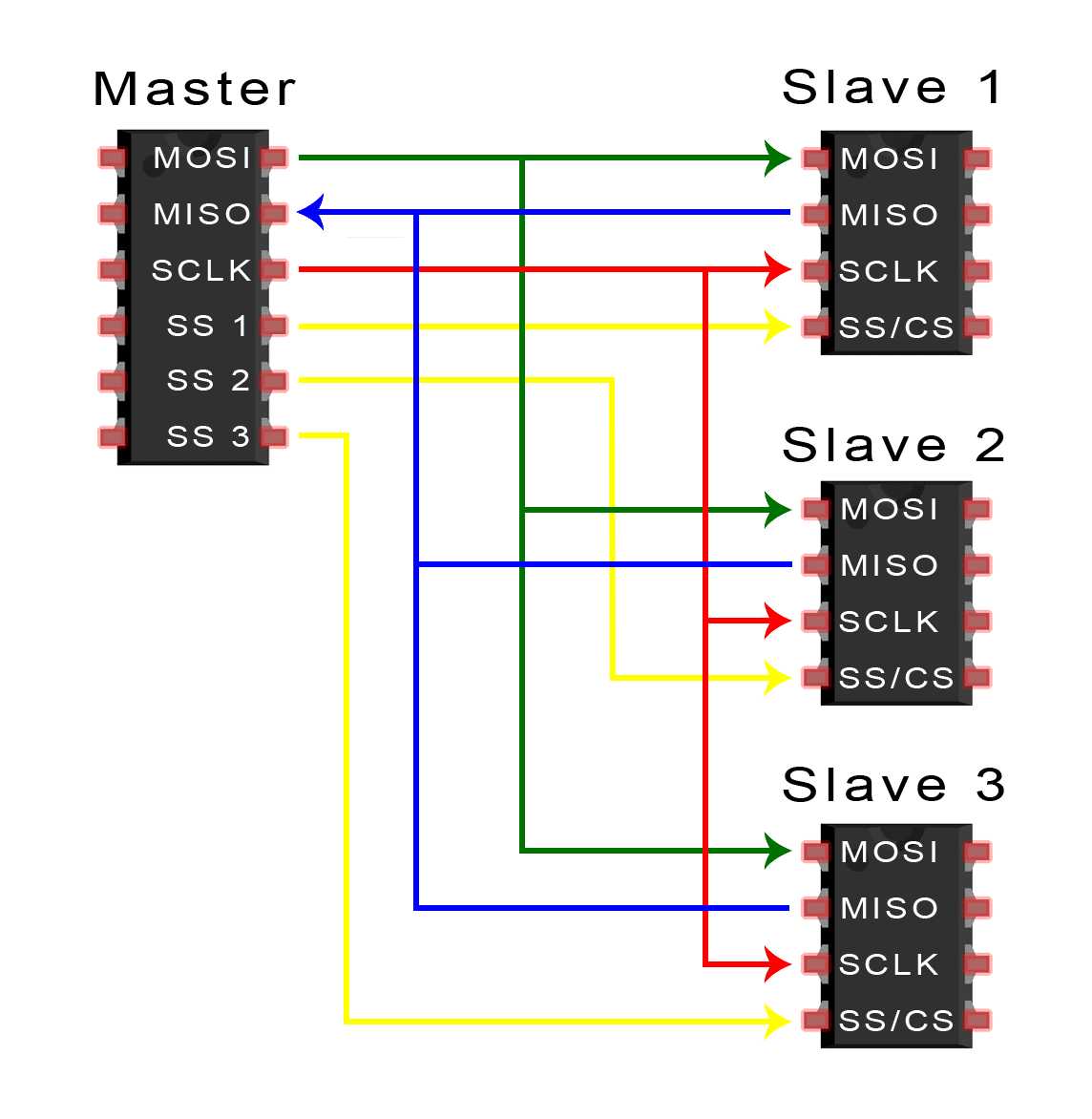
This image was taken from Circuit Basics .com page and if you like to download it or know more about SPI Protocol please click on this link
UART communication
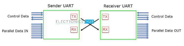
In UART communication, two UARTs communicate directly with each other. The transmitting UART converts parallel data from a controlling device like a CPU into serial form, transmits it in serial to the receiving UART, which then converts the serial data back into parallel data for the receiving device. Only two wires are needed to transmit data between two UARTs. Data flows from the Tx pin of the transmitting UART to the Rx pin of the receiving UART:
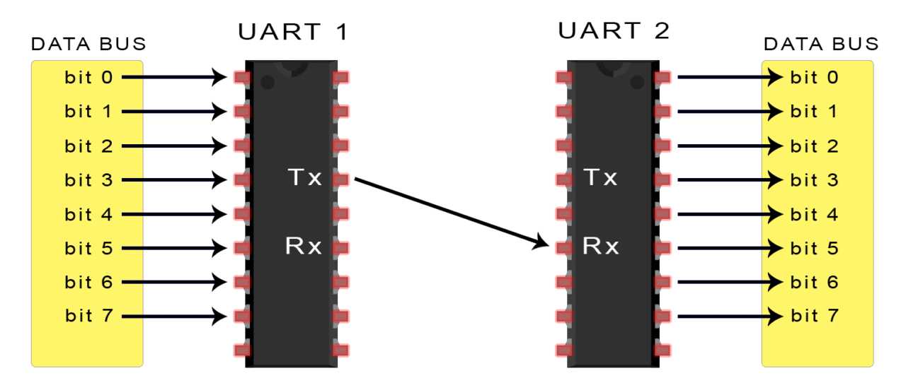
This image was taken from Circuit Basics .com page and if you like to download it or know more about UART Protocol please click on this link
UARTs transmit data asynchronously, which means there is no clock signal to synchronize the output of bits from the transmitting UART to the sampling of bits by the receiving UART. Instead of a clock signal, the transmitting UART adds start and stop bits to the data packet being transferred. These bits define the beginning and end of the data packet so the receiving UART knows when to start reading the bits.
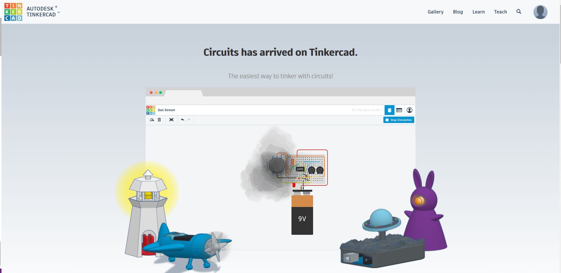
Tinkercad
Tinkercad Circuit is a free, online Circuit Designing tool that runs in a web browser, known for its simplicity and ease of use . and is very usefull to design and simulate many components.
If you want to try it out you go to there official website by clicking on this link
Our purpose behind using tinkercad was That , during this week we were in a Lockdown due to COVID 19 pandamic and due to which we were not able to work on any of the physical stuf , so rather then wasting
                                                 time our Mentor Neil suggested that we should use tinkercad as it is a virtual platfrorm where we can simulte whole circuit and all the components as well , plus we can upload real code and check how its work and when we get back to lab we will , directly starts working with our PCB and output devices
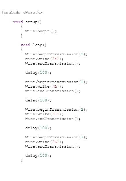
Trying i2c communication
Master program
                                            #include

                                                void setup()
                                                   {
                                                     Wire.begin();
                                                   }

                                                   void loop()
                                                   {
                                                     Wire.beginTransmission(1);
                                                     Wire.write('H');
                                                     Wire.endTransmission();

                                                     delay(100);

                                                     Wire.beginTransmission(1);
                                                     Wire.write('L');
                                                     Wire.endTransmission();

                                                     delay(100);

                                                     Wire.beginTransmission(2);
                                                     Wire.write('H');
                                                     Wire.endTransmission();

                                                     delay(100);

                                                     Wire.beginTransmission(2);
                                                     Wire.write('L');
                                                     Wire.endTransmission();

                                                     delay(100);
                                                   }
And if you want to download the CODE which i used ,you can click on this link for that
ARDUINO_MASTERCODE OF SLAVE 1
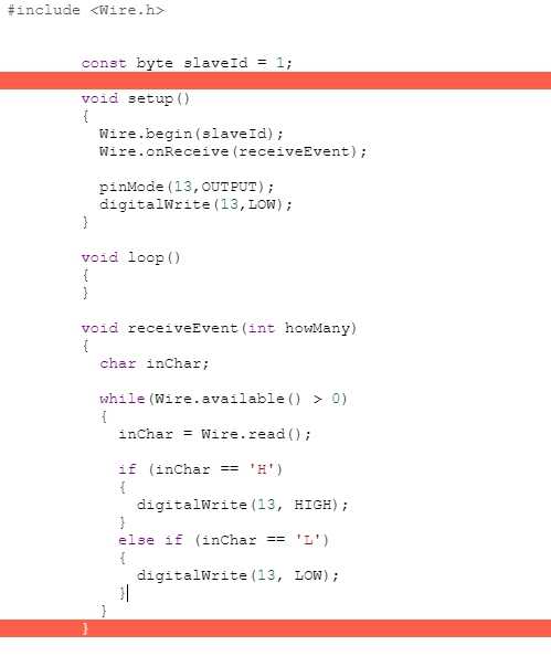
                                            #include


                                                const byte slaveId = 1;

                                                void setup()
                                                {
                                                  Wire.begin(slaveId);
                                                  Wire.onReceive(receiveEvent);

                                                  pinMode(13,OUTPUT);
                                                  digitalWrite(13,LOW);
                                                }

                                                void loop()
                                                {
                                                }

                                                void receiveEvent(int howMany)
                                                {
                                                  char inChar;

                                                  while(Wire.available() > 0)
                                                  {
                                                    inChar = Wire.read();

                                                    if (inChar == 'H')
                                                    {
                                                      digitalWrite(13, HIGH);
                                                    }
                                                    else if (inChar == 'L')
                                                    {
                                                      digitalWrite(13, LOW);
                                                    }
                                                  }
                                                }
And if you want to download the CODE which i used ,you can click on this link for that
ARDUINO_SLAVE_1CODE OF SLAVE 2
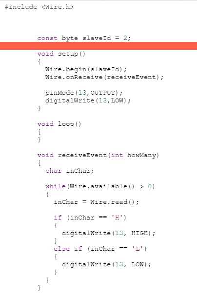
                                            #include


                                            const byte slaveId = 2;

                                            void setup()
                                            {
                                              Wire.begin(slaveId);
                                              Wire.onReceive(receiveEvent);

                                              pinMode(13,OUTPUT);
                                              digitalWrite(13,LOW);
                                            }

                                            void loop()
                                            {
                                            }

                                            void receiveEvent(int howMany)
                                            {
                                              char inChar;

                                              while(Wire.available() > 0)
                                              {
                                                inChar = Wire.read();

                                                if (inChar == 'H')
                                                {
                                                  digitalWrite(13, HIGH);
                                                }
                                                else if (inChar == 'L')
                                                {
                                                  digitalWrite(13, LOW);
                                                }
                                              }
                                            }
And if you want to download the CODE which i used ,you can click on this link for that
ARDUINO_SLAVE_2After lockdown
After lockdown was over i tried to program the arduino and simulate same thing which i did on tinker cad , trying to communicating them with each other , using the same code
Individual Assignment:
Design, build, and connect wired or wireless node(s) with network or bus addresses
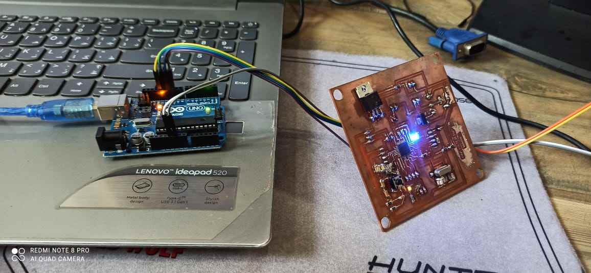
For this purpose i am using my final project board i.e FAB FILTER ISP , as it has 2 RX-TX FOR communication therefore it will be node 1 andfor node 2 i will be using my Neo echo board which i made in week 7 , you can chekc it by clicking on this link
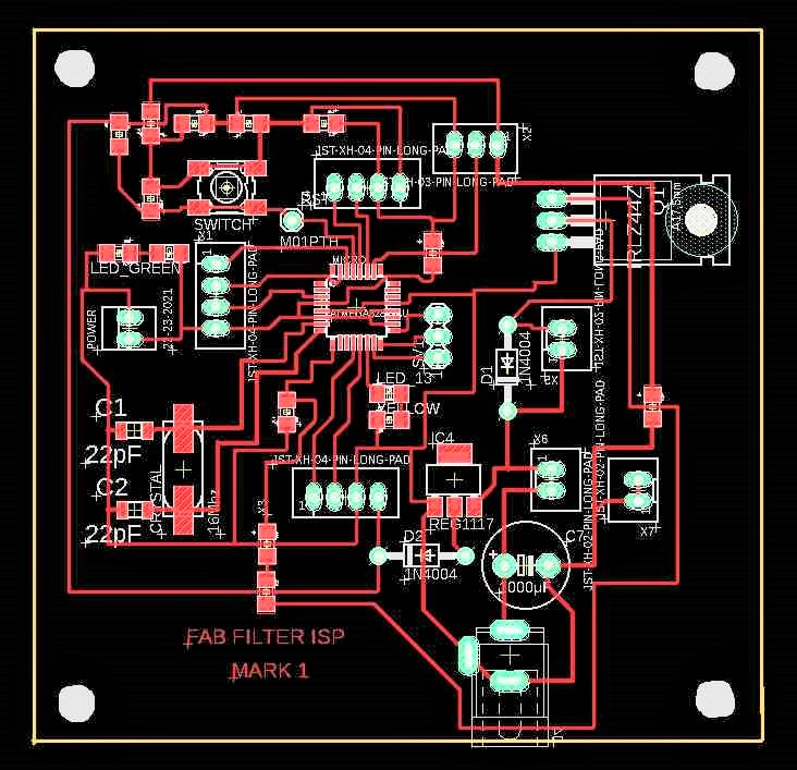
This is my FAB FILTER ISP
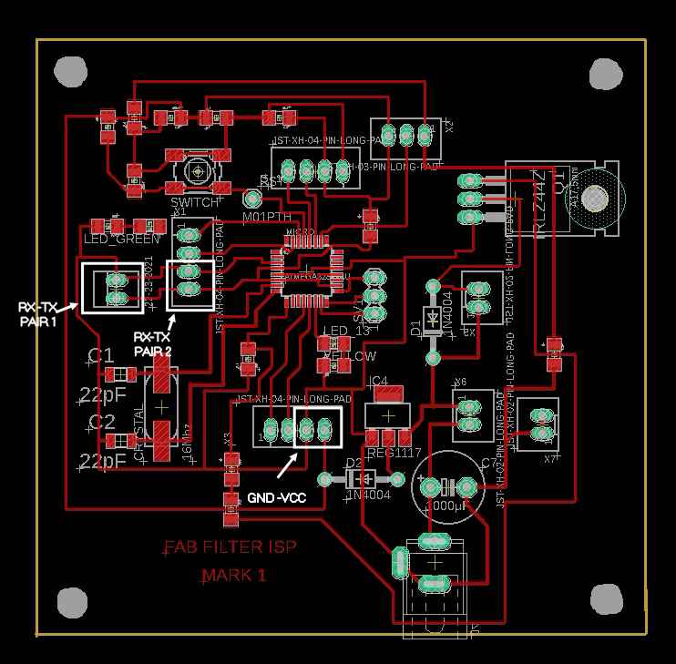
As you can see i have added 2 pair of RX-TX TO it and Vcc- Gnd ass well
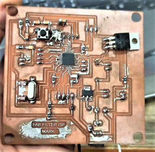
An image of soldered PCB
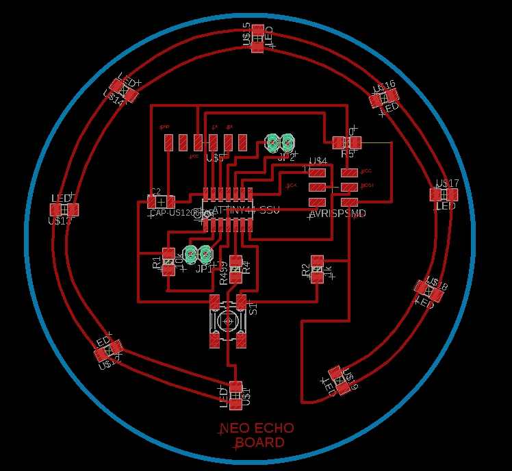
This will be my NEO echo board
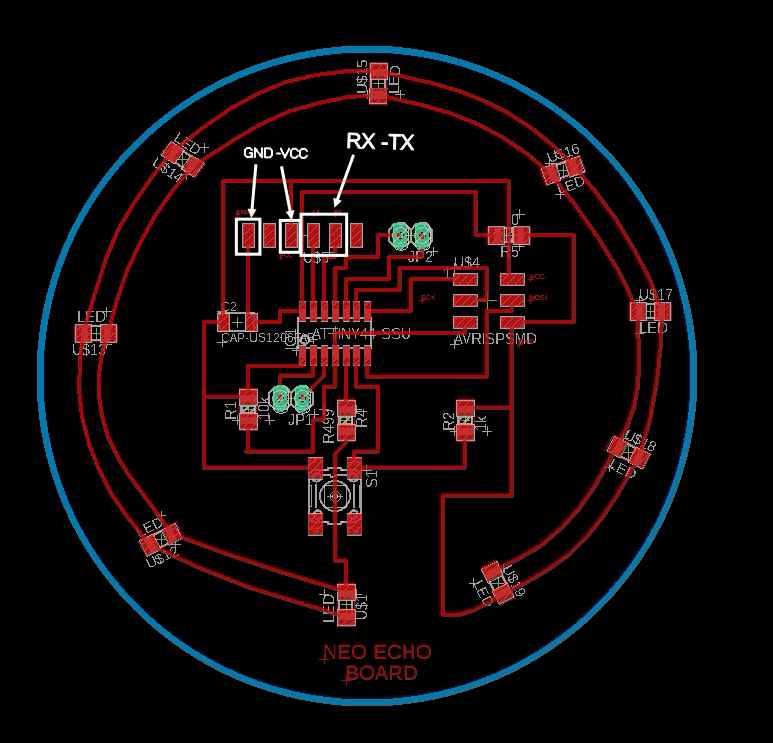
well it doen't have 2 pair of RX -TX so i decided to make it node 2
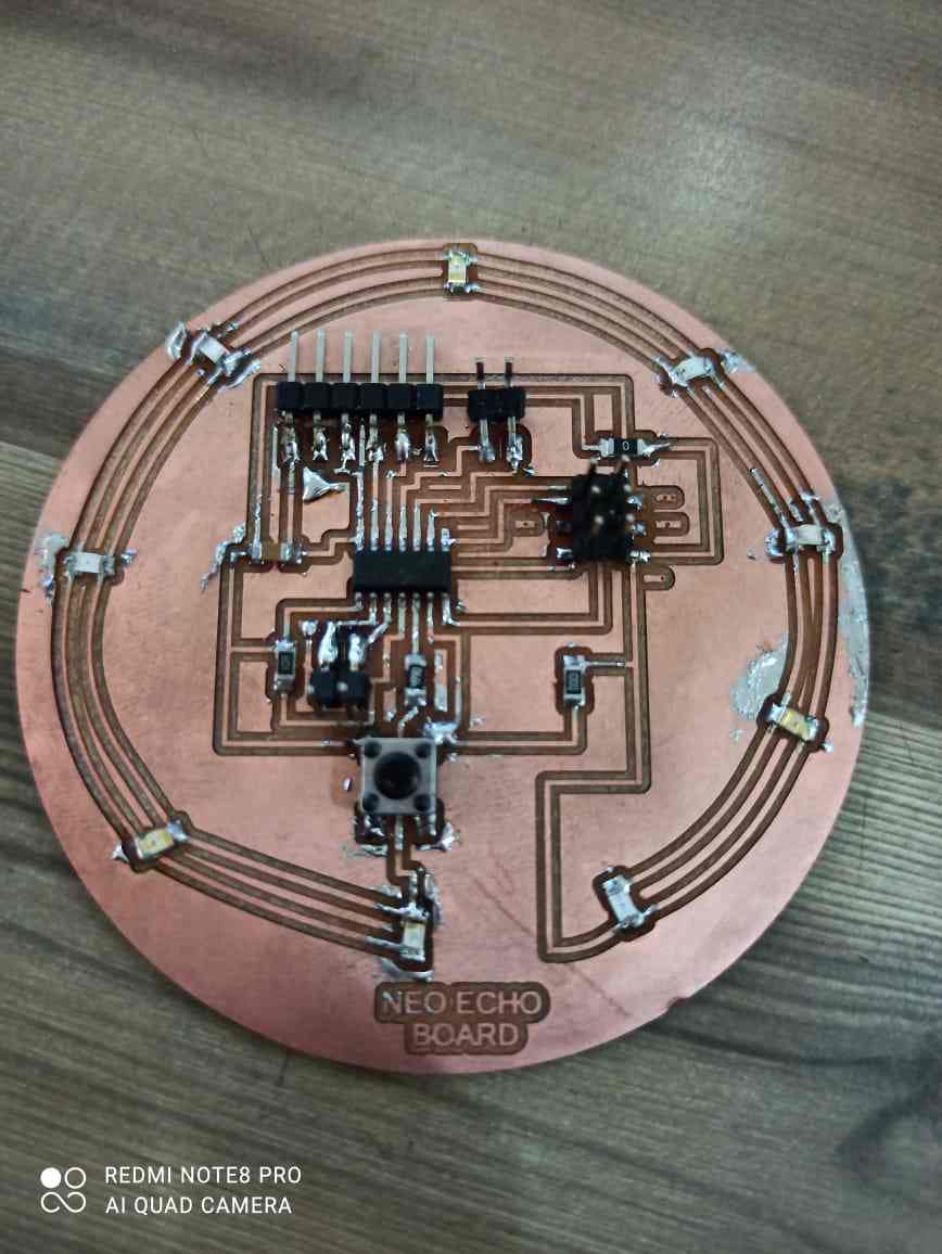
Fully soldered pcb
Starting with programming
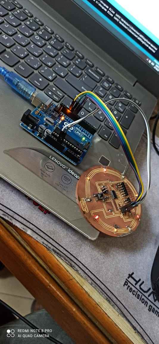
First connected my Neo echo board pcb with arduino to program it and uploaded the code for node 2

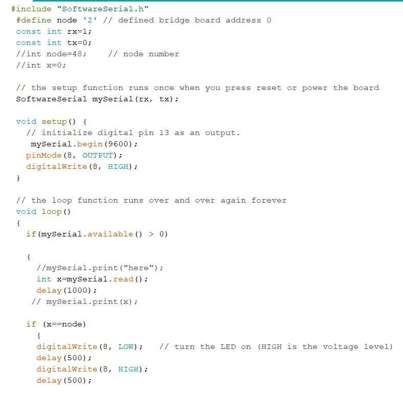
Code for NODE 2
                                            #include "SoftwareSerial.h"
                                            #define node '2' // defined bridge board address 0
                                            const int rx=1;
                                            const int tx=0;
                                            //int node=48;    // node number
                                            //int x=0;

                                            // the setup function runs once when you press reset or power the board
                                            SoftwareSerial mySerial(rx, tx);

                                            void setup() {
                                              // initialize digital pin 13 as an output.
                                               mySerial.begin(9600);
                                              pinMode(8, OUTPUT);
                                              digitalWrite(8, HIGH);
                                            }

                                            // the loop function runs over and over again forever
                                            void loop()
                                            {
                                              if(mySerial.available() > 0)

                                              {
                                                //mySerial.print("here");
                                                int x=mySerial.read();
                                                delay(1000);
                                               // mySerial.print(x);

                                              if (x==node)
                                                {
                                                digitalWrite(8, LOW);   // turn the LED on (HIGH is the voltage level)
                                                delay(500);
                                                digitalWrite(8, HIGH);
                                                delay(500);

                                                    }
                                              }
                                            }
you can use this code by just clicking and copying it
And if you want to download the CODE which i used ,you can click on this link for that
NODE_2This is video of controlling Neo echo boardfrom serial monitor
Node 1
Connecting the wire from arduino to My board
Programming the board through Arduino IDE
                                            #include "SoftwareSerial.h"
                                            #define node '1' // defined bridge board address 0
                                            const int rx=0;
                                            const int tx=1;
                                            //int node=48;    // node number
                                            //int x=0;

                                            // the setup function runs once when you press reset or power the board
                                            SoftwareSerial mySerial(rx, tx);

                                            void setup() {
                                              // initialize digital pin 13 as an output.
                                               mySerial.begin(9600);
                                              pinMode(8, OUTPUT);
                                              digitalWrite(8, HIGH);
                                            }

                                            // the loop function runs over and over again forever
                                            void loop()
                                            {
                                              if(mySerial.available() > 0)

                                              {
                                                //mySerial.print("here");
                                                int x=mySerial.read();
                                                delay(1000);
                                               // mySerial.print(x);

                                              if (x==node)
                                                {
                                                digitalWrite(8, LOW);   // turn the LED on (HIGH is the voltage level)
                                                delay(500);
                                                digitalWrite(8, HIGH);
                                                delay(500);

                                                    }
                                              }
                                            }
you can use this code by just clicking and copying it
And if you want to download the CODE which i used ,you can click on this link for that
NODE_1First time my pcb didnt respond to my command , and i was not able to understand the proble as my connections were tight , but i came to know that i accidntly gave wrong software serial number ,
After correcting the code i tried again and it works
Then i connected both PCB using extra pair of RX-TX Given in my NODE 1 Pcb and you can see it works well
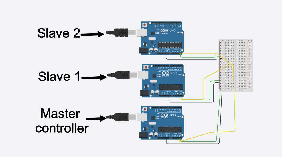
Group Assignment:
Our PCBs of the final projects were ready so we thought of programming our boards to make a communication between them. We used the same code as uploded in the individual assignment and a communication between the boards were achieved. Again it is important to have the exact value that you must put for the RX and TX pins becuase these are the pins responsible for the communication between the boards.
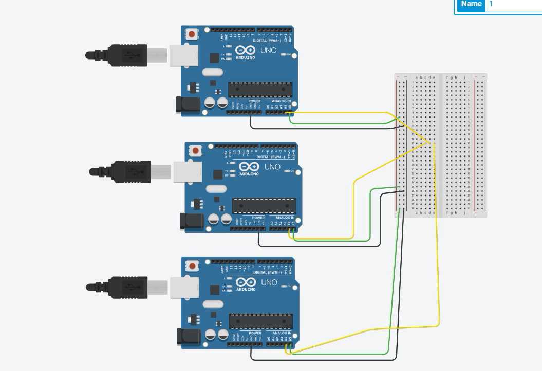
We have connected every ones final board in the same manner as what i did above and individually uploaded the program to every pcb , this time difference is that , we have 3 Node with us , so the change in code is to add a NODE 3 when programming and as you can see it worked
Code for Node 3
                                            #include "SoftwareSerial.h"
                                            #define node '3' // defined bridge board address 0
                                            const int rx=0;
                                            const int tx=1;
                                            //int node=48;    // node number
                                            //int x=0;

                                            // the setup function runs once when you press reset or power the board
                                            SoftwareSerial mySerial(rx, tx);

                                            void setup() {
                                              // initialize digital pin 13 as an output.
                                               mySerial.begin(9600);
                                              pinMode(8, OUTPUT);
                                              digitalWrite(8, HIGH);
                                            }

                                            // the loop function runs over and over again forever
                                            void loop()
                                            {
                                              if(mySerial.available() > 0)

                                              {
                                                //mySerial.print("here");
                                                int x=mySerial.read();
                                                delay(1000);
                                               // mySerial.print(x);

                                              if (x==node)
                                                {
                                                digitalWrite(8, LOW);   // turn the LED on (HIGH is the voltage level)
                                                delay(500);
                                                digitalWrite(8, HIGH);
                                                delay(500);

                                                    }
                                              }
                                            }
you can use this code by just clicking and copying it
And if you want to download the CODE which i used ,you can click on this link for that
NODE_3Well the basic principle behind this networking is that when we upload the code to all our pcb and connected them using I2C
communication , we make sure that every pcb has there own address like slave "1" or node"1" and respectively slave"2" or node "2" and
when we send signal ussing serial monitor the pcb is made to recognise that set of command if we enter 0 and no pcb is listed as Slave "0"
no one will wil respond to command , but if its lave "1" The pcb respective PCB will respond and blink