OUTPUT DEVICES
-
This week we have a group assignment and an individual assignment .
-
The group assignment for this week is to measure the power consumption of an output device .
-
The individual assignment for this week is to add an output device to a microcontroller board i have designed, and program it to do something .
So i have used Tinkercad simulation tool since i do not have the lad access. In this simulation i have used a servo motor o be derived by a thermistor and a potentiometter.
Program code
In Tinkercad we have the option of coding through text and as well as by the use of the blocks. so i tries to do the programing through blocks as it does not require you to think much about punctuation marks.
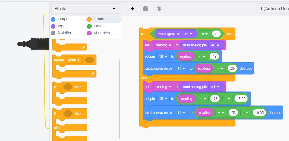
The code in the text form is automatically generated if there is no error in the block format.
                    #include "Servo.h"


                    int reading = 0;


                    Servo servo_11;


                    void setup()

                    {

                      pinMode(12, INPUT);

                      pinMode(A0, INPUT);

                      pinMode(10, OUTPUT);

                      servo_11.attach(11);


                      pinMode(A1, INPUT);

                    }


                    void loop()

                    {

                      if (digitalRead(12) == 0) {

                        reading = analogRead(A0);

                        analogWrite(10, (reading * 0.18));

                        servo_11.write((reading * 0.25));

                      } else {

                        reading = analogRead(A1);

                        analogWrite(10, ((reading + 0.75) - 15.09));

                        servo_11.write(((reading + 0.53) - 10.65));

                      }

                      delay(10); // Delay a little bit to improve simulation performance

                    }
Details about output devices
Servo motor
A servo motor is an electrical device which can push or rotate an object with great precision. If you want to rotate and object at some specific angles or distance, then you use servo motor. It is just made up of simple motor which run through servo mechanism. If motor is used is DC powered then it is called DC servo motor, and if it is AC powered motor then it is called AC servo motor. We can get a very high torque servo motor in a small and light weight packages. Doe to these features they are being used in many applications like toy car, RC helicopters and planes, Robotics, Machine etc. I refereed to this video for info of servomotor. Source:Circuitdigest.com
Stepper Motor
A stepper motor is an electromechanical device it converts electrical power into mechanical power. Also it is a brushless, synchronous electric motor that can divide a full rotation into an expansive number of steps. The motor’s position can be controlled accurately without any feedback mechanism, as long as the motor is carefully sized to the application. Source:elprous.com
The output device which i am going to use is a fan and a geared dc motor. The fan will move when the temperature of the room goes above a certain value and lullabyy toy will be installed to a geared DC motor since the rpm in this type of motor is lesser as compared to DC motors. In my design i have given a supply of 12 volt to the motors as it will be difficult to rotate the motors with the 5volt suppllyyy and this was suggested tto me by my insturctor.
Geared DC motor
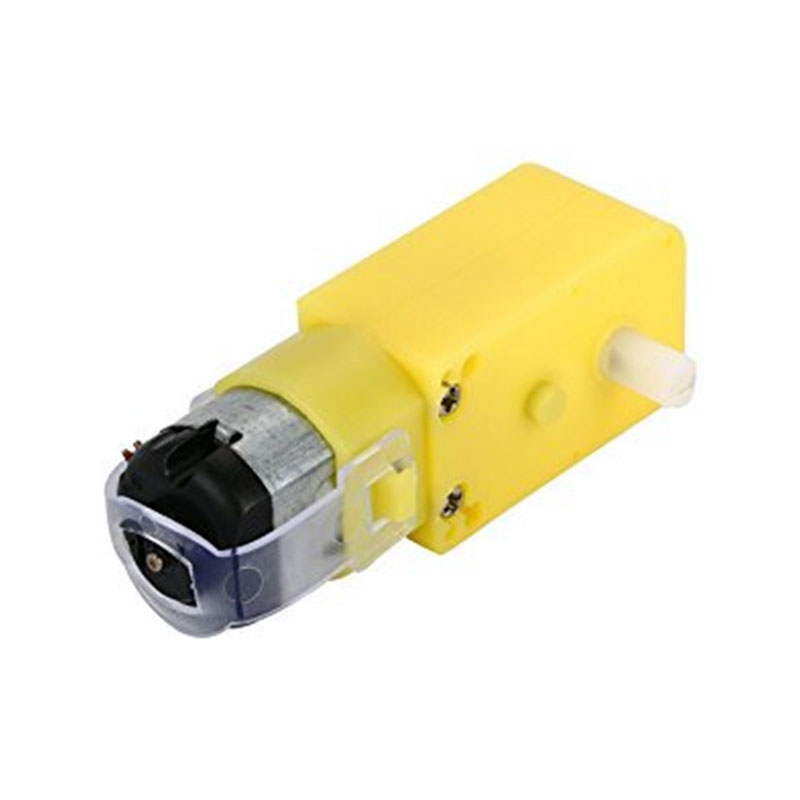
A geared DC Motor has a gear assembly attached to the motor. The speed of motor is counted in terms of rotations of the shaft per minute and is termed as RPM .The gear assembly helps in increasing the torque and reducing the speed. Using the correct combination of gears in a gear motor, its speed can be reduced to any desirable figure.
This page helped me a lot in understanding the way the connections should be made to rotate a dc motor according to the input given to it.
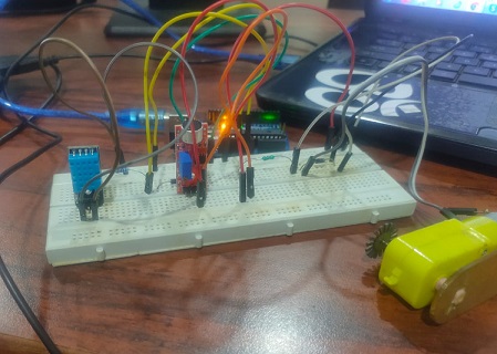
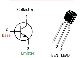
The connections i have used is like i have used an PN2222 Transistor and 1N4001 diode o rotate the motor. since i want to rotate the motor in one direction itself thats the reason i am not using a motor driver. a motor driver facilitates the movement of the motor in either directions and at variable speeds. I had tested this on arduino board with simple embedded codes and i just cannot tell you the feeling of happiness when you see your motor running. It is very importatnt to remember the orientation of the diode and the orientation of the transistor as well since the legs of the transistor determines the Emitter Base and Collector.
The board i am using is the one which is used for the final project. The program is also
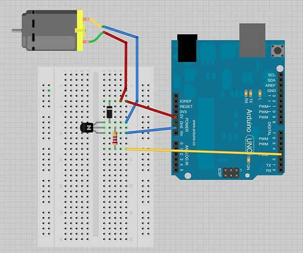
This is how i connected my motor and used the program to run it. It is important to remember that the jumper wires connections should be proper with the breadboard
This is the code which i used to check the wokring of my mottor.
        void setup() {

  pinMode(3, OUTPUT);
}

// the loop function runs over and over again forever
void loop() {
  digitalWrite(3, HIGH);   // turn the motor on (HIGH is the voltage level)
  delay(1000);                       // wait for a second
  digitalWrite(3, LOW);    // turn the motor off by making the voltage LOW
  delay(1000);                       // wait for a second
}
I had to see some video lectures to understand how the motor works and i also had tto see the option of applying a mottor driver to the circuit but since the arrangement of diode and trasnsistor were working to drive the motor so i just left the option of motor driver. The transistor acts like a switch, controlling the power to the motor. the diode stops the reverse current. The program was such that it will incraese or decraese the RPM of the motor according to the given condition. The input which i had to give to the serial monitor is between 0 to 255 where the speed will be maximum when at 255 and it will stop at 0. but during my trial i found that the motor was making humming sound at less than 50 and and was not moving till 50 but after that it started to show some rotation.
I have designed a board for my final project which consists of the arrangement for the input and as well as for the output device as well. I programmed the board in such a manner that if the value of the sound goes above a certain value then the motor starts to move. The song is being played on the mobile phone which is actuting the motor to run.
You can see the design of the board and the program on this Page.
The motor connection with the microcontroller can be a bit different as motor drivers has be to be installed with them. I experimented with L293D motor driver on the arduino board and found out that the motor drivers are used if we want to control the direction of movement of the motors.
This video helped me to understand the connections of the motor driver with the microcontroller. To operate one motor you need to have four signal pins connected to the motor driver but in case if ou do not need the movement in different directions then connection of the motor with the transisitr will also do.
Board
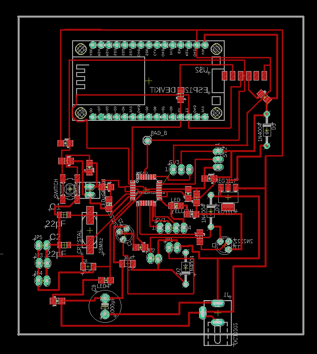
The motor starts to run when the sound level of the sound senosor goes above a certain threshold value. The code i have used here is the same which i used with my final project board. To see the code for the motor you can visit this page.
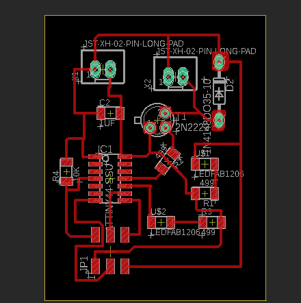
NEW OUTPUT DEVICE BOARD
So I am designing a new board for this week. In this board also i am going to take a DC motor as the output device and design the board. I am taking the same components as i took in my previous design to drive a motor which are one PN2222 Transistor, one 1N4001 diode resistor and motors and i am going to use ATTINY 44 as the microcontroller this time. In my previous design i had the ATMEGA328P as the microcontroller.
So i checked if the arrangement is working or not on a breadboard with the help of arduino UNO.
Schemetic
The board is designed and the process of designing the board can be seen on Page.
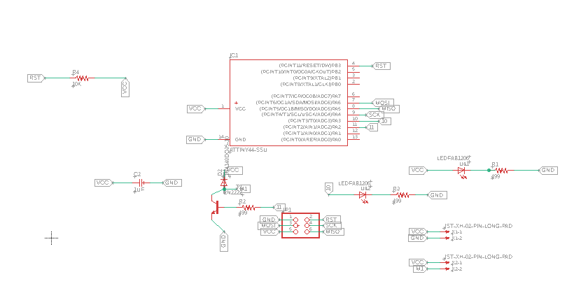
Download EAGLE DESIGN FILES
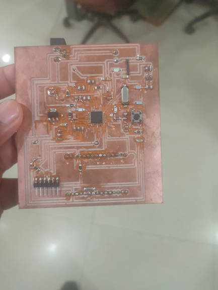
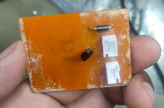
The output board is milled and the program for the its operation is uploaded. You can see the process of uploading the program on Attiny 44 on this page.
The program which i have used is
                void setup() {

  pinMode(2, OUTPUT); // pin2 is initilazed as output pin
}

// the loop function runs over and over again forever
void loop() {
  digitalWrite(2, HIGH);   // turn the motor on (HIGH is the voltage level)
  delay(5000);                       // wait for 5 second
  digitalWrite(2, LOW);    // turn the motor off by making the voltage LOW
  delay(5000);                       // wait for 5 second
}
The motor ran as per the code provoded to it. The motor ran for 5 seconds and then it stopped for 5 seconds.
The important thing to remeber here is that you should use the correct pin number in the code by checking the pin configuration otherwise it becomes difficult to debug.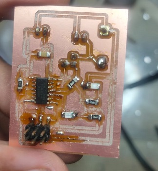
GROUP ASSIGNMENT
In group assignment we have to measure power of output device.So we decided to measure power consumption of DC Geared motor.
We Connected the Motor to a Variable power supply and observed the current drawn by the motor
Observations
It may be noticed that the current drawn by the motor @ 4 V is about 60mA, and the current drawn by motor @ 10.5 V is about 110mA. So the Power consumption is about :
- Using formula P=VI
- Here P = Power
- >V = voltage
- I = Current
- P = 0.06 * 4 = 0.24 Watt
- P = 0.11 * 10.5 =1.15 Watt
- So the power consumed by motor at No load ranges from 0.24 Watts - 1.1 Watts
Problems Faced and mistakes done
The problem i faced was that i made the whole arrangement for the final project and was testing the program on the braedboard with the arduuino uno. I had earlier also tested the arrangement with the different programs and it had worked earlier. But this time i made arangement to see the working but to found out that the nothing is working. I checked the arragement 10 times and checked my program but to no use. Then one of my collegue told me to change the jumper wires which i am using and found that it started working with new jumper wires. So the biggest problem creators can be the jumper wires as well. So before using them just check the continuity with the multimeter to make sure that your jumper wires are working correctly.
While designing my board i did not mirror the pads for the transistors and fortunately my colleague Afsha saw this and i changed it becuase that it had to be installed beneath the board. So this is important to remember it.